
STEEL BUILDINGS IN EUROPE
Multi-Storey Steel Buildings
Part 3: Actions


Multi-Storey Steel Buildings
Part 3: Actions

3
-
ii

Part 3: Actions
FOREWORD
This publication is part three of a design guide, Multi-Storey Steel Buildings.
The 10 parts in the Multi-Storey Steel Buildings guide are:
Part 1: Architect’s guide
Part 2: Concept design
Part 3: Actions
Part 4: Detailed design
Part 5: Joint design
Part 6: Fire Engineering
Part 7: Model construction specification
Part 8: Description of member resistance calculator
Part 9: Description of simple connection resistance calculator
Part 10: Guidance to developers of software for the design of composite beams
Multi-Storey Steel Buildings is one of two design guides. The second design guide is
Single-Storey Steel Buildings.
The two design guides have been produced in the framework of the European project
“Facilitating the market development for sections in industrial halls and low rise
buildings (SECHALO) RFS2-CT-2008-0030”.
The design guides have been prepared under the direction of Arcelor Mittal, Peiner
Träger and Corus. The technical content has been prepared by CTICM and SCI,
collaborating as the Steel Alliance.
3 - iii

Part 3: Actions
3 - iv

Part 3: Actions
Contents
Page No
SAFETY PHILOSOPHY ACCORDING TO EN 1990
General format of the verifications
Ultimate limit states and serviceability limit states
Characteristic values and design values of actions
Reduction due to the loaded area
Reduction due to the number of storeys
Worked Example – Wind action on a multi-storey building
3 - v

Part 3: Actions
3 - vi
SUMMARY
This document provides guidelines for the determination of the loads on a common
multi-storey building, according to EN 1990 and EN 1991. After a short description of
the general format for limit state design, this guide provides information on the
determination of the permanent actions, the variable actions and the combinations of
actions. This guide also includes a worked example on the wind action on a multi-storey
building.

Part 3: Actions
1
INTRODUCTION
This guide provides essential information on the determination of the design
actions on a multi-storey building. It describes the basis of design with
reference to the limit state concept in conjunction with the partial factor
method, according to the following parts of the Eurocodes:
EN 1990: Basis of structural design
[1]
EN 1991: Actions on structures
- Part 1-1: General actions – Densities, self-weight, imposed loads for
buildings
[2]
- Part 1-3: General actions – Snow loads
[3]
- Part 1-4: General actions – Wind actions
[4]
- Part 1-5: General actions – Thermal actions
[5]
- Part 1-6: General actions – Actions during execution.
[6]
3 - 1

Part 3: Actions
2
SAFETY PHILOSOPHY ACCORDING TO
EN 1990
2.1
General format of the verifications
A distinction is made between ultimate limit states (ULS) and serviceability
limit states (SLS).
The ultimate limit states are related to the following design situations:
Persistent design situations (conditions of normal use)
Transient design situations (temporary conditions applicable to the
structure, e.g. during execution, repair, etc.)
Accidental design situations (exceptional conditions applicable to the
structure)
Seismic design situations (conditions applicable to the structure when
subjected to seismic events). These events are dealt with in EN 1998
[7]
, and
are outside the scope of this guide.
The serviceability limit states concern the functioning of the structure under
normal use, the comfort of people and the appearance of the construction.
The verifications shall be carried out for all relevant design situations and load
cases.
2.2
Ultimate limit states and serviceability limit states
2.2.1
Ultimate limit states (ULS)
The states classified as ultimate limit states are those that concern the safety of
people and /or the safety of the structure. The structure shall be verified at ULS
when there is:
Loss of equilibrium of the structure or any part of it (EQU)
Failure by excessive deformation, rupture, loss of stability of the structure
or any part of it (STR)
Failure or excessive deformation of the ground (GEO)
Failure caused by fatigue or other time-dependent effects (FAT).
2.2.2
Serviceability limit states (SLS)
The structure shall be verified at SLS when there is:
Deformations that affect the appearance, the comfort of users or the
functioning of the structure
Vibrations that cause discomfort to people or that limit the functional
effectiveness of the structure
Damage that is likely to adversely affect the appearance, the durability or
the functioning of the structure.
3 - 2

Part 3: Actions
2.3
Characteristic values and design values of
actions
2.3.1
General
Actions shall be classified by their variation in time as follows:
Permanent actions (G), e.g. self-weight of structures, fixed equipment, etc.
Variable actions (Q), e.g. imposed loads, wind actions, snow loads, etc.
Accidental actions (A), e.g. explosions, impact from vehicles, etc.
Certain actions may be considered as either accidental and/or variable actions,
e.g. seismic actions, snow loads, wind actions with some design situations.
2.3.2
Characteristic values of actions
The characteristic value (F
k
) of an action is its principal representative value.
As it can be defined on statistical bases, it is chosen so as to correspond to a
prescribed probability of not exceeding on the unfavourable side, during a
“reference period” taking into account the design working life of the structure.
These characteristic values are specified in the various Parts of EN 1991.
2.3.3
Design values of actions
The design value F
d
of an action F can be expressed in general terms as:
F
d
=
f
F
k
where:
F
k
is the characteristic value of the action
f
is a partial factor for the action
is either 1,00,
0
,
1
or
2
2.3.4
Partial factors
Partial factors are used to verify the structures at ULS and SLS. They should be
obtained from EN 1990 Annex A1, or from EN 1991 or from the relevant
National Annex.
2.3.5
factors
In the combinations of actions,
factors apply to variable actions in order to
take into account the reduced probability of simultaneous occurrence of their
characteristic values.
The recommended values for
factors for buildings should be obtained from
EN 1990 Annex A1 Table A1.1, or from EN 1991 or from the relevant
National Annex.
3 - 3

Part 3: Actions
3
COMBINATIONS OF ACTIONS
3.1
General
The individual actions should be combined so as not to exceed the limit state
for the relevant design situations.
Actions that cannot occur simultaneously, e.g. due to physical reasons, should
not be considered together in a same combination.
Depending on its uses and the form and the location of a building, the
combinations of actions may be based on not more than two variable actions –
See Note 1 in EN 1990 § A1.2.1(1). The National Annex may provide
additional information.
3.2
ULS combinations
3.2.1
Static equilibrium
To verify a limit state of static equilibrium of the structure (EQU), it shall be
ensured that:
E
d,dst
≤ E
d,stb
where:
E
d,dst
is the design value of the effect of destabilising actions
E
d,stb
is the design value of the effect of stabilising actions
3.2.2
Rupture or excessive deformation of an element
To verify a limit state of rupture or excessive deformation of a section, member
or connection (STR and/or GEO), it shall be ensured that:
E
d
≤ R
d
where:
E
d
is the design value of the effect of actions
R
d
is the design value of the corresponding resistance
Each combination of actions should include a leading variable action or an
accidental action.
3.2.3
Combinations of actions for persistent or transient design
situations
According to EN 1990 § 6.4.3.2(3), the combinations of actions can be derived
either from expression (6.10) or from expressions (6.10a and 6.10b –
whichever is more onerous). The choice between these two sets of expressions
may be imposed by the National Annex.
In general, expression (6.10) is conservative in comparison to the pair of
expressions (6.10a and 6.10b), but it leads to a reduced number of
combinations to consider.
3 - 4
Part 3: Actions
Permanent
Leading
variable action
Accompanying
variable actions
actions
1
j
k,
j
G,
j
G
1
i
k,
i
0,
i
Q,
i
Q
k,1
Q,1
Q
E
d
=
+
+
(6.10)
1
j
k,
j
G,
j
G
1
i
k,
i
0,
i
Q,
i
Q
k,1
Q,1
0,1
Q
E
d
=
+
+
(6.10a)
1
j
k,
j
G,
j
G
1
i
k,
i
0,
i
Q,
i
Q
k,1
Q,1
Q
E
d
=
+
+
(6.10b)
G
k
and
Q
k
are found in EN 1991 or its National Annex.
G
and
Q
are found in Table A1.2(A) for static equilibrium (EQU);
Tables A1.2(B) and A1.2(C) for rupture (STR and/or GEO) of EN 1990 or its
National Annex.
Table 3.1
Recommended values of partial factors
Table
Limit state
Gj,inf
Gj,sup
Q,1
=
Q,I
Q,1
=
Q,I
(EN 1990)
A1.2(A)
EQU
0,90
1,10
1,50
1,50
A1.2(B)
STR/GEO
1,00
1,35
1,50
1,50
A1.2(C)
STR/GEO
1,00
1,00
1,30
1,30
0
factors are found in EN 1990 Table A1.1 or in its National Annex. This
factor varies between 0,5 and 1 except for roofs of category H (
0
= 0).
ξ is a reduction factor for permanent loads. According to EN 1990
Table A1.2(B), the recommended value for buildings is
ξ = 0,85. The National
Annex may specify a different value.
For example, according to expression 6.10:
With snow as the leading variable action:
E
d
= 1,35
G + 1,5 S + (1,5
0,6) W = 1,35 G + 1,5 S + 0,9 W
With wind as the leading variable action:
E
d
= 1,35
G + 1,5 W + (1,5
0,5) S = 1,35 G + 1,5 W + 0,75 S
3.2.4
Combinations of actions for accidental design situations
Combinations of actions for accidental design situations should either involve
an explicit accidental action or refer to a situation after an accident event.
Permanent
Accidental
Leading variable
action
Accompanying
variable actions
actions
action
(
or
E
d
=
1
j
k,
j
G
+
A
d
+
1,1
2,1
)
1
i
k,
i
0,
i
Q,
i
Q
+
k,1
Q
3 - 5
Part 3: Actions
The choice between
1,1
Q
k,1
or
2,1
Q
k,1
should be related to the relevant
accidental design situation. Guidance is given in EN 1990 or in the National
Annex to EN 1990.
3.3
SLS combinations
3.3.1
Serviceability Limit State
To verify a serviceability limit state, it shall be ensured that:
E
d
≤
C
d
where:
E
d
is the design value of the effects of actions specified in the
serviceability criterion,
C
d
is the limiting design value of the relevant serviceability criterion.
3.3.2
Characteristic combination
The characteristic combination is normally used for irreversible limit states.
Permanent
Leading
variable action
Accompanying
variable actions
actions
1
j
k,
j
G
1
i
k,
i
0,
i
Q
k,1
Q
E
d
=
+
+
For example, with snow as the leading variable action:
E
d
=
G + S + 0,6 W
E
d
=
G + S + 0,7 Q (Q being the imposed load in an office building)
3.3.3
Frequent combination
The frequent combination is normally used for reversible limit states.
Permanent
Leading
variable action
Accompanying
variable actions
actions
1
j
k,
j
G
1
i
k,
i
2,
i
Q
k,1
1,1
Q
E
d
=
+
+
For example, with snow as the leading variable action:
E
d
=
G + 0,2 S (
2
= 0 for the wind action)
E
d
=
G + 0,2 S + 0,3 Q (Q being the imposed load in an office building)
3 - 6

Part 3: Actions
3.3.4
Quasi-permanent combination
The quasi-permanent combination is normally used for long-term effects and
the appearance of the structure.
Permanent
Variable
actions
actions
1
j
k,
j
G
1
i
k,
i
2,
i
Q
E
d
=
+
For example:
E
d
=
G + 0,3 Q (Q being the imposed load in an office building)
3.3.5
Floor vibration
In multi-storey buildings, floor vibration is sometimes a serviceability limit
state that is critical in the design. There is no specific rule in the Eurocodes.
Limits may be given in the National Annexes.
A simple rule is generally to require the frequency to be higher than a
minimum value (3 or 5 Hz for example); the frequency being assessed from the
total permanent loads and a fraction of the imposed loads
I (for example:
G + 0,2 I). This approach is often too conservative and more advanced methods
are available, see the
Design guide for floor vibrations
[8]
. additional
information is given in
Multi-storey steel buildings. Part 4: Detailed design
[9]
.
3 - 7

Part 3: Actions
4
PERMANENT ACTIONS
The self-weight of construction works is generally the main permanent load.
As stated in EN 1991-1-1 § 2.1(1), it should be classified as a permanent fixed
action
The total self-weight of structural and non-structural members, including fixed
services, should be taken into account in combinations of actions as a single
action.
Non-structural elements include roofing, surfacing and coverings, partitions
and linings, hand rails, safety barriers, parapets, wall claddings, suspended
ceilings, thermal insulation, fixed machinery and all fixed services (equipment
for lifts and moving stairways, heating, ventilating, electrical and air
conditioning equipment, pipes without their contents, cable trunking and
conduits).
The characteristic values of self-weight should be defined from the dimensions
and densities of the elements.
Values of densities of construction materials are provided in EN 1991-1-1
Annex A (Tables A.1 to A.5).
For example:
Steel:
= 77,0 to 78,5 kN/m
3
Normal reinforced concrete
= 25,0 kN/m
3
Aluminium:
= 27,0 kN/m
3
For manufactured elements (façades, ceilings and other equipment for
buildings), data may be provided by the manufacturer.
3 - 8

Part 3: Actions
5
CONSTRUCTION LOADS
EN 1991-1-6 gives rules for the determination of actions during execution.
Verifications are required for both serviceability limit states and ultimate limit
states.
Table 4.1 defines construction loads that have to be taken into account:
Personnel and hand tools (Q
ca
)
Storage of movable items (Q
cb
)
Non permanent equipment (Q
cc
)
Moveable heavy machinery and equipment (Q
cd
)
Accumulation of waste material (Q
ce
)
Loads from parts of structure in a temporary state (Q
cf
).
Recommended values are provided in the same table but values may be given
in the National Annex.
In multi-storey buildings, the design of composite floors or composite beams
should be carried out with reference to EN 1991-1-6 § 4.11.2 for the
determination of the construction loads during the casting of concrete.
3 - 9

Part 3: Actions
6
IMPOSED LOADS
6.1
General
Generally, imposed loads on buildings shall be classified as variable free
actions. They arise from occupancy. They include normal use by persons,
furniture and moveable objects, vehicles, anticipating rare events
(concentrations of persons or of furniture, momentary moving or stacking of
objects, etc.). Movable partitions should be treated as imposed loads.
Imposed loads are represented by uniformly distributed loads, line loads or
point loads applied on roofs or floors, or a combination of these loads.
Floor and roof areas in buildings are sub-divided into categories according to
their use (Table 6.1). The characteristic values
q
k
(uniformly distributed load)
and
Q
k
(concentred load) related to these categories are specified in Table 6.2
(or in the National Annex).
For the design of a single floor or a roof, the imposed load shall be taken into
account as a free action applied at the most unfavourable part of the influence
area of the action effects considered.
Where the loads on other storeys are relevant, they may be assumed to be
distributed uniformly (fixed actions).
Characteristic values of imposed loads are specified in EN
1991-1-1
Section 6.3 as follows:
6.3.1 Residential, social, commercial and administration areas
6.3.2 Areas for storage and industrial activities
6.3.3 Garages and vehicle traffic areas
6.3.4 Roofs.
6.2
Reduction due to the loaded area
In multi-storey buildings, the characteristic value
q
k
of the imposed loads on
floors and accessible roofs may be reduced by a factor
A
, for categories A to
D, where:
A
=
0
,
1
7
5
0
0
A
A
With the restriction for categories C and D:
A
≥ 0,6
where:
0
is the factor as defined in EN 1990 Annex A1 Table A1.1.
0
= 10 m
2
A
is the loaded area
The National Annex may give an alternative method.
3 - 10
Part 3: Actions
6.3
Reduction due to the number of storeys
For the design of columns and walls, loaded from several storeys, the total
imposed loads on the floor of each storey should be assumed to be distributed
uniformly.
For columns and walls, the total imposed loads may be reduced by a factor
n
,
for categories A to D, where:
n
=
0
)
2
(
2
n
n
where:
0
is is the factor as defined in EN 1990 Annex A1 Table A1.1.
n
is the number of storeys (> 2) above the loaded structural elements in
the same category.
The National Annex may give an alternative method.
6.4
Horizontal loads on parapets
The characteristic values of the line loads q
k
acting at the height of the partition
walls or parapets but not higher than 1,20 m should be taken from EN 1991-1-1
Table 6.12, which provides recommended values. Other values may be given in
the National Annex.
For areas susceptible to significant overcrowding associated with public events
(stages, assembly halls, conference rooms), the load should be taken according
to category C5 from EN 1991-1-1 Table 6.1.
For office buildings (category B), the recommended value from EN 1991-1-1
Table 6.12 is:
q
k
= 0,2 to 1,0 kN/m
The National Annex may define other values.
3 - 11

Part 3: Actions
7
SNOW LOADS
There is no issue in the calculation of snow loads specifically related to
multi-storey buildings. Full information including a worked example is
provided in Single-storey steel buildings. Part 3: Actions
[10]
.
3 - 12

Part 3: Actions
8
WIND ACTION
8.1
General
The determination of the wind action according to EN 1991-1-4
[4]
is described
in Single-storey steel buildings. Part 3:– Actions
[10]
for a single storey
building. For a multi-storey building, the calculation is nearly the same, except
for two aspects:
The calculation of the structural factor c
s
c
d
For slender buildings, the external pressure coefficients must be calculated
for different strips along the height of the building.
According to EN 1991-1-4 § 6.2(1), the structural factor may be taken equal
to 1 when the height of the building is lower than 15 m, which is commonly the
case for single storey buildings. For multi-storey buildings, which are
commonly higher than 15 m, the structural factor has to be determined.
Section 8.2 provides the main steps of this calculation according to
EN 1991-1-4 § 6.3.1(1).
A detailed example including the full calculation of the wind action on a multi-
storey building is given in Appendix A.
8.2
Structural factor c
s
c
d
The structural factor c
s
c
d
should be calculated for the main wind directions,
using the equation given EN 1991-1-4 § 6.3.1(1), provided that:
The building shape is a rectangular, parallel sided as stated in EN 1991-1-4
§ 6.3.1(2) and Figure 6.1
The along-wind vibration in the fundamental mode is significant and the
mode shape has a constant sign.
This calculation requires the determination of several intermediate parameters.
3 - 13
Part 3: Actions
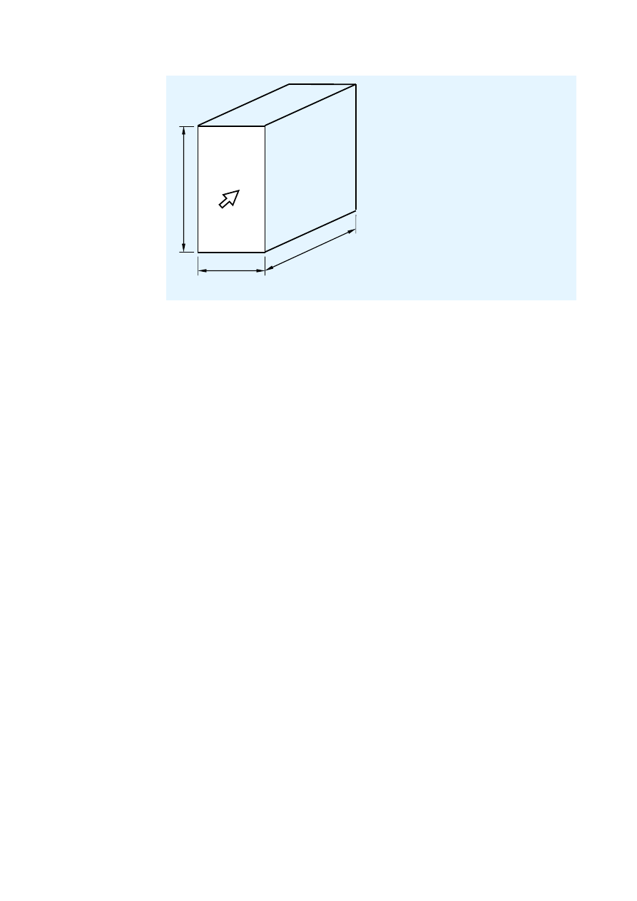
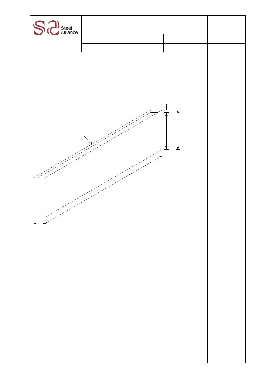
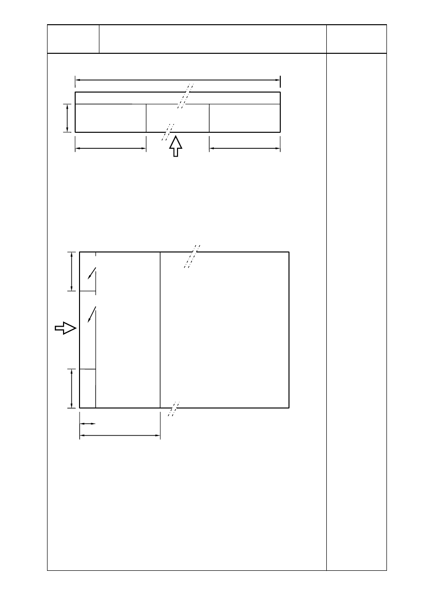
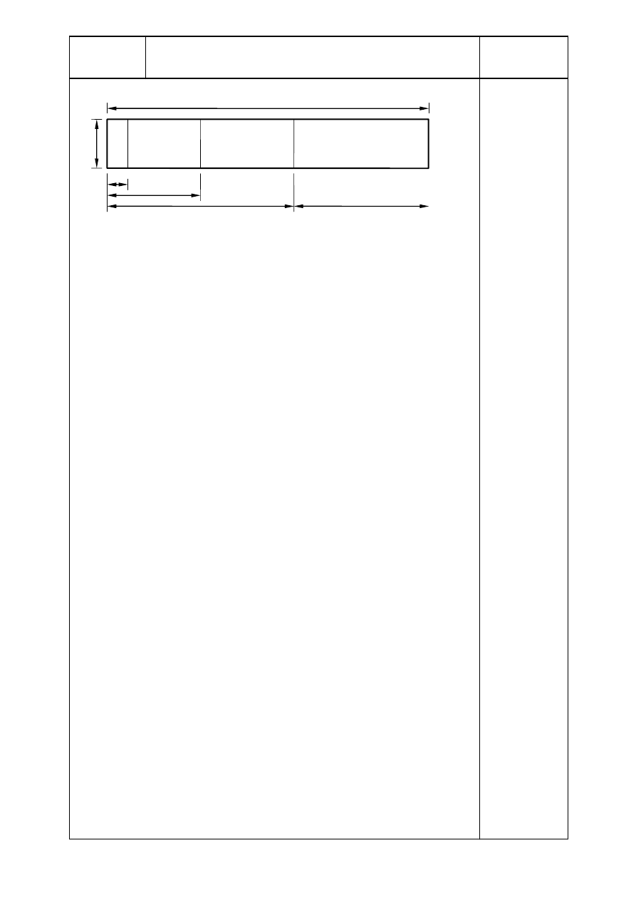
b
d
h
W
W indicates the wind direction
Figure 8.1
General dimensions of a building
The following procedure is proposed:
The roughness length z
0
and the minimum height z
min
1.
2.
3.
4.
5.
These values are obtained from EN 1991-1-4 Table 4.1, depending on the
terrain category.
The reference height z
s
z
s
=
0,6
h (h is the height of the multi-storey building)
But
z
s
should not be taken lower than z
min
.
The orography factor c
o
(z
s
)
According to EN 1991-1-4 § 4.3.3, the effects of orography may be
neglected when the average slope of the upwind terrain is less than 3°.
Then:
c
o
(z
s
) = 1,0
Otherwise, this factor can be determined either from EN 1991-1-4 §A.3, or
from the relevant National Annex.
The roughness factor c
r
(z
s
)
c
r
(z
s
) has to be calculated for the reference height according to EN 1991-1-4
§ 4.3.2:
If
z
min
≤ z
s
≤ z
max
c
r
(z
s
) = 0,19 (z
0
/z
0,II
)
0,07
ln(z
s
/z
0
)
Else,
if
z
s
< z
min
c
r
(z
s
) = c
r
(z
min
)
where: z
0,II
= 0,05 m and z
max
= 200 m
The turbulence factor k
l
It may be defined by the National Annex. The recommended value is:
k
l
= 1,0
3 - 14
Part 3: Actions
The turbulence intensity I
v
(z
s
)
6.
7.
8.
If
z
min
≤ z
s
≤ z
max
I
v
(z
s
) = k
l
/ [c
0
(z
s
) ln(z
s
/z
0
) ]
Else,
if
z
s
< z
min
I
v
(z
s
) = I
v
(z
min
)
where:
z
max
= 200 m
The turbulent length scale L(z
s
)
If
z
min
≥ z
s
L(z
s
) = L
t
(z
s
/z
t
)
Else,
if
z
s
< z
min
L(z
s
) = L(z
min
)
where:
= 0,67 + 0,05 ln(z
0
) [z
0
in meters]
L
t
= 300 m
z
t
= 200 m
Note: Some of the following parameters are determined using EN 1991-1-4
Annex B as recommended method. They can also be defined by the
National Annex.
The background factor B
2
0,63
s
2
)
(
0,9
1
1
z
h
b
B
L
The mean wind velocity v
m
(z
s
)
9.
10.
The mean wind velocity at the reference height z
s
is calculated from:
v
m
(z
s
) = c
0
(z
s
) c
r
(z
s
) v
b
Where v
b
is the basic wind velocity as defined in EN 1991-1-4 § 4.2(2).
The fundamental frequency n
1,x
The procedure requires the determination of the fundamental frequency of
the building in the wind direction. The following formula can be used for
common buildings in order to get a rough estimation of the fundamental
frequency in Hertz:
h
d
1
,
0
n
1,x
=
With d and h in meters.
Complementary information can be found in the ECCS recommendations
for calculating the effect of wind on constructions
[11]
.
The non-dimensional power spectral density function S
L
(z
s
, n
1,x
)
11.
3
5
x
1,
s
L
x
1,
s
L
,
2
,
10
1
,
8
,
6
n
z
f
n
z
f
S
L
(z
s
,n
1,x
) =
3 - 15
Part 3: Actions
where:
f
L
(z
s
,n
1,x
) =
s
m
s
x
,
1
z
z
L
n
12.
13.
The logarithmic decrement of structural damping
s
s
= 0,05 for a steel building (EN 1991-1-4 Table F.2).
The logarithmic decrement of aerodynamic damping δ
a
The logarithmic decrement of aerodynamic damping for the fundamental
mode is calculated according to EN 1991-1-4 § F.5(4):
a
=
e
x
1,
s
m
f
2
)
(
m
n
z
v
b
c
where:
c
f
is the force coefficient in the wind direction
c
f
= c
f,0
r
(EN-1991-1-4 § 7.6(1)
For common buildings, the reduction factors
r
and
can be taken
equal to 1,0.
c
f,0
is obtained from EN 1991-1-4 Figure 7.23.
is the air density as defined in EN 1991-1-4 § 4.5(1). The
recommended value is:
= 1,25 kg/m
3
m
e
is the equivalent mass per unit length according to EN 1991-1-4
§ F.4. For a multi-storey building, when the mass is
approximately the same for all the storeys, it can be taken equal
to the mass per unit length m. m
e
is therefore the total mass of
the building divided by its height.
14.
15.
16.
17.
The logarithmic decrement of damping due to special devices
d
d
= 0 when no special device is used.
The logarithmic decrement
=
s
+
a
+
d
The aerodynamic admittance functions R
h
and R
b
They are calculated using the equation given in EN 1991-1-4 § B.2(6) in
function of parameters defined above: b, h, L(z
s
), f
L
(z
s
, n
1,x
).
The resonance response factor R
2
b
h
,
1
s
L
2
2
,
2
R
R
n
z
S
R
x
The peak factor k
p
18.
The peak factor can be calculated as (EN 1991-1-4 § B.2(3)):
3 - 16
Part 3: Actions
0
,
3
;
)
(
l
2
6
,
0
)
(
l
2
Max
p
T
n
T
n
k
where:
v
=
Hz
,08
0
;
Max
2
2
2
,
1
R
B
R
n
x
T
is the averaging time for the mean wind velocity: T = 600 s
Finally, the structural factor c
s
c
d
can be calculated:
19.
)
(
7
1
)
(
2
1
s
v
2
2
s
v
p
d
s
z
I
R
B
z
I
k
c
c
3 - 17

Part 3: Actions
9
EFFECT OF TEMPERATURE
Buildings not exposed to daily or seasonal climatic changes may not need to be
assessed under thermal actions. For large buildings, it is generally good
practice to design the building with expansion joints so that the temperature
changes do not induce internal forces in the structure. Information about the
design of expansion joints is given in Section 6.4 of Multi-storey steel
buildings. Part 2: Concept design
[12]
.
When the effects of temperature have to be taken into account, EN 1993-1-5
provides rules to determine them.
3 - 18

Part 3: Actions
3 - 19
REFERENCES
1 EN 1990:2002: Eurocode Basis of structural design
2 EN 1991-1-1:2002: Eurocode 1 Actions on structures. General actions.
Densities, self-weight, imposed loads for buildings
3 EN 1991-1-3:2003: Eurocode 1 Actions on structures. General actions.
Snow loads
4 EN 1991-1-4:2005: Eurocode 1 Actions on structures. General actions.
Wind actions
5 EN 1991-1-5:2003: Eurocode 1 Actions on structures. General actions.
Thermal actions
6 EN 1991-1-6:2005: Eurocode 1 Actions on structures. General actions.
Actions during execution.
7 EN 1998-1:2004: Eurocode 8 Design of structures for earthquake
resistance. General rules, seismic actions and rules for buildings
8 HECHLER, O., FELDMANN, M., HEINEMEYER, C. and GALANTI, F.
Design guide for floor vibrations
Eurosteel 2008.
9 Steel Buildings in Europe
Multi-storey steel buildings. Part 4: Detailed design
10 Steel Buildings in Europe
Single-storey steel buildings. Part 3: Actions
11 Recommendations for calculating the effect of wind on constructions
Publication No. 52. 1987. ECCS-CECM-EKS
(Available on the web site: www.steel-construct.com)
12 Recommendations for calculating the effect of wind on constructions
Publication No. 52. 1987. ECCS-CECM-EKS
(Available on the web site: www.steel-construct.com)

Part 3: Actions
3 - 20

Part 3: Actions
3 - 21
APPENDIX A
Worked Example: Wind action on a multi-storey
building
22
APPENDIX A. Worked Example: Wind action
on a multi-storey building
1
18
of
Made
by
DC
02/2009
Date
Calculation sheet
Checked
by
AB
03/2009
Date
1. Data
This worked example deals with the determination of the wind action on a
multi-storey building according to EN 1991-1-4.
10 m
120 m
h
h
h
p
=
1,
50 m
0
=
33,
50 m
=
35,
00 m
1
1 Parapet
Figure A.1 Dimensions of the building
The building is erected on a suburban terrain where the average slope of the
upwind terrain is low (3°).
The terrain roughness is the same all around and there are no large and tall
buildings in the neighbourhood.
The fundamental value of the basic wind velocity is:
V
b,0
= 26 m/s
The roof slope is such that:
< 5°
Title
Appendix A Worked Example: Wind action on a multi-storey building
2
of 18
3 - 23
2.1.
2.2.
2.
Peak velocity pressure
General
For a multi-storey building, the peak velocity pressure generally depends on
the wind direction because the height of the building is higher than the width
of the upwind face. Therefore we have to distinguish between:
Wind on the long side
Wind on the gable
The calculation of the peak velocity pressure is performed according to the
detailed procedure described in Section 7.2.1 of Single-storey steel buildings.
Part 3: Actions
10]
.
Wind on the long side
1 Fundamental value of the basic wind velocity
v
b,0
= 26 m/s
2 Basic wind velocity
EN 1991-1-4
v
b
= c
dir
c
season
v
b,0
§ 4.2(2)
For c
dir
and c
season
, the recommended values are:
c
dir
=
1,0
c
season
= 1,0
Then: v
b
=
v
b,0
= 26 m/s
3 Basic velocity pressure
EN 1991-1-4
2
b
b
2
1
v
q
§ 4.5(1)
where:
= 1,25 kg/m
3
Then: q
b
= 0,5 × 1,25 × 26
2
= 422,5 N/m
2
4 Terrain factor
EN 1991-1-4
k
r
= 0,19 (z
0
/ z
0,II
)
0,07
§ 4.3.2(1)
The terrain category is III. Then:
z
0
= 0,3 m (and z
min
= 5 m)
z
0,II
= 0,05 m
Then:
k
r
= 0,19 × (0,3 / 0,05)
0,07
= 0,215
5 Roughness factor
EN 1991-1-4
§ 4.3.2
c
r
(z) = k
r
ln(z/z
0
) for:
z
min
≤ z ≤ z
max
c
r
(z) = c
r
(z
min
) for:
z ≤ z
min
Title
Appendix A Worked Example: Wind action on a multi-storey building
3
of 18
3 - 24
2.3.
where:
z
max
= 200 m
z
is the reference height
The total height of the building is: h = 35 m
The width of the wall is:
b = 120 m
h ≤ b therefore q
p
(z) = q
p
(z
e
) with: z
e
= h = 35 m
Therefore c
r
(z) = 0,215 × ln(35/0,3) = 1,023
EN 1991-1-4
Figure 7.4
6 Orography factor
Since the slope of the terrain is lower than 3°, the recommended value is
used:
c
o
(z) = 1,0
EN 1991-1-4
§ 4.3.3
7 Turbulence factor
The recommended value is used:
k
l
= 1,0
EN 1991-1-4
§ 4.4(1)
8 Peak velocity pressure
q
p
(z) = [1 + 7 I
v
(z)] × 0,5
v
m
2
(z)
EN 1991-1-4
§ 4.5(1)
where:
= 1,25 kg/m
3
(recommended value)
v
m
(z) is the mean wind velocity at height z above the terrain
v
m
(z) = c
r
(z) c
o
(z) v
b
= 1,023 × 1,0 × 26
= 26,6 m/s
I
v
(z) is the turbulence intensity
I
v
(z) =
k
l
/ [c
0
(z) ln(z/z
0
) ]
for: z
min
≤ z ≤ z
max
I
v
(z) =
I
v
(z
min
) for:
z ≤ z
min
Then:
I
v
(z) = 1,0 / [1,0 × ln(35/0,3)] = 0,21
q
p
(z)
= [1 + 7 × 0,21] × 0,5 × 1,25 × 26,6
2
× 10
-3
= 1,09 kN/m
2
Wind on the gable
Several parameters are identical to the case of wind on the long side, as
follows:
1 Fundamental value of the basic wind velocity
v
b,0
= 26 m/s
2 Basic wind velocity
v
b
= 26 m/s
EN 1991-1-4
§ 4.2(2)
Title
Appendix A Worked Example: Wind action on a multi-storey building
4
of 18
3 - 25
3 Basic velocity pressure
q
b
= 422,5 N/m
2
§ 4.5(1)
4 Terrain factor
k
r
= 0,215
§ 4.3.2(1)
5 Roughness factor
§ 4.3.2
The total height of the building is: h = 35 m
The width of the wall is:
b = 10 m
h > 2b
Therefore several strips are considered:
-
The lower strip between 0 and b = 10 m
-
The upper strip between (h – b) = 25 m and h = 35 m
Intermediate strips with a height taken equal to: h
strip
= 5 m
The values of c
r
(z) are given in Table A.1.
EN 1991-1-4
Figure 7.4
6 Orography factor
c
o
(z) = 1,0
EN 1991-1-4
§ 4.3.3
7 Turbulence factor
k
l
= 1,0
§ 4.4(1)
8 Peak velocity pressure
The peak velocity pressure is calculated for each strip, with z = z
e
which is
the position of the top of the strip (see Table A.1).
Table A.1
Peak velocity pressure – Wind on the gable
z
e
c
r
(z)
v
m
(z)
m/s
I
v
(z)
q
p
(z)
kN/m
2
0 10
m 0,75 19,5 0,29 0,72
10 m
15 m
0,84
21,8
0,26
0,84
15 m
20 m
0,90
23,4
0,24
0,92
20 m
25 m
0,95
24,7
0,23
1,00
25 m
35 m
1,02
26,5
0,21
1,09
Title
Appendix A Worked Example: Wind action on a multi-storey building
5
of 18
3 - 26
3.1.
3. Wind
pressure
External pressure coefficients
3.1.1. Vertical
walls
Wind on the long side:
b
= 120 m (crosswind dimension)
d
= 10 m
h
= 35 m
h / d = 3,5
e
= Min(b ; 2 h) = 70 m
EN 1991-1-4
§ 7.2.2(2)
Figure 7.5
Table 7.1
Zone A (gables):
c
pe,10
= -1,2 (e > 5d)
Zone D (upwind):
c
pe,10
= +0,8
Zone E (downwind):
c
pe,10
= -0,6
Wind on the gable:
b
= 10 m (crosswind dimension)
d
= 120 m
h
= 35 m
h / d = 0,29
e
= Min(b ; 2 h) = 10 m
EN 1991-1-4
§ 7.2.2(2)
Figure 7.5
Table 7.1
Long sides:
Zone A:
c
pe,10
= -1,2 (e < d) along e/5 = 2 m
Zone B:
c
pe,10
= -0,8 along 4/5 e = 8 m
Zone C:
c
pe,10
= -0,5
Gables (h/d
0,25):
Zone D (upwind):
c
pe,10
= +0,7
Zone E (downwind):
c
pe,10
= -0,3 (by linear interpolation)
3.1.2. Flat roof with parapets
The external pressure coefficients depend on the ratio:
h
p
/ h
0
= 1,50 / 33,50 = 0,045
Wind on the long side:
e
= Min(b = 120 m ; 2 h
0
= 67 m) = 67 m
The external pressure coefficients are given in Figure A.2 for wind on the
long side.
EN 1991-1-4
§ 7.2.3
Figure 7.6
Table 7.2
ilding
6
of 18
3 - 27
Title
Appendix A Worked Example: Wind action on a multi-storey bu
e
/4 = 16,75 m
e
/10 =
6
,70 m
F: c
pe,10
= -1,4
e
/4 = 16,75 m
120 m
H: c
pe,10
= -0,7
G: c
pe,10
= -0,9
F: c
pe,10
= -1,4
Figure A.2 External pressure coefficients on the roof – Wind on the long side
Wind on the gable:
e
= Min(b = 10 m ; 2 h
0
= 67 m) = 10 m
The external pressure coefficients are given in Figure A.3 for wind on a gable.
e
/4
=
2,
50
m
H: c
pe,10
= -0,7
F: c
pe,10
= -1,4
F
G: c
pe,10
= -0,9
I: c
pe,10
= -0,2
e
/10 = 1,00 m
e
/2 = 5,00 m
e
/4 =
2,
50 m
Figure A.3 External pressure coefficients on the roof – Wind on the gable
Title
Appendix A Worked Example: Wind action on a multi-storey building
7
of 18
3 - 28
3.2. Structural
factor
3.2.1. General
The structural factor c
s
c
d
is calculated from the following equation, for wind
on the long side and for wind on the gable:
EN 1991-1-4
§ 6.3.1
)
(
7
1
.
)
(
2
1
s
v
2
2
s
v
p
d
s
z
I
R
B
z
I
k
c
c
The calculation is performed according to the procedure given in Section 8.2
of this guide.
3.2.2. Wind on the long side
Dimensions: b = 120 m and h = 35 m
EN 1991-1-4
Table 4.1
1 The terrain category is III.
Then: z
0
= 0,30 m and z
min
= 5 m
2 Reference height:
EN 1991-1-4
z
s
= 0,6 h = 0,6 × 35 = 21 m (> z
min
= 5 m)
Figure 6.1
3 Orography factor
EN 1991-1-4
Since the slope of the upwind terrain is less than 3°, c
0
(z
s
) = 1,0
§ 4.3.3
4 Roughness factor
EN 1991-1-4
Since z
min
≤ z
s
≤ z
max
(= 200 m)
§ 4.3.2
c
r
(z
s
) = 0,19 (z
0
/z
0,II
)
0,07
ln(z
s
/z
0
)
= 0,19 × (0,3 / 0,05)
0,07
× ln(21/0,3)
=
0,915
5 Turbulence factor (recommended value):
EN 1991-1-4
k
l
= 1,0
§ 4.4(1)
6 Turbulence intensity
Since z
min
≤ z
s
≤ z
max
(= 200 m)
EN 1991-1-4
I
v
(z
s
) = k
l
/ [c
0
(z
s
) ln(z
s
/z
0
) ]
§ 4.4(1)
= 1,0 / [1,0 × ln(21 / 0,3)]
=
0,235
7 Turbulent length scale
Since z
s
> z
min
:
L(z
s
) = L
t
(z
s
/z
t
)
EN 1991-1-4
§ B.1(1)
L
t
= 300 m
z
t
= 200 m
= 0,67 + 0,05 ln(z
0
) = 0,67 + 0,05 ln(0,30) = 0,61
Then: L(z
s
) = 300 × (21/200)
0,61
= 75,9 m
Title
Appendix A Worked Example: Wind action on a multi-storey building
8
of 18
3 - 29
8 Background factor
EN 1991-1-4
415
,
0
9
,
75
35
120
0,9
1
1
0,9
1
1
0,63
0,63
s
2
z
L
h
b
B
§ B.2(2)
9 Mean wind velocity at the reference height z
s
EN 1991-1-4
v
m
(z
s
) =
c
r
(z
s
) c
0
(z
s
) v
b
§ 4.3.1
= 0,915 × 1,0 × 26 = 23,8 m/s
10 Fundamental frequency n
1,x
h
d
0,1
It is estimated by the simplified formula: n
1,x
=
35
0,1
10
n
1,x
=
= 0,9 Hz
11 Non dimensional power spectral density function
3
/
5
x
,
1
s
L
x
,
1
s
L
x
,
1
s
L
)
,
(
10,2
1
)
,
(
8
,
6
)
,
(
n
z
f
n
z
f
n
z
S
EN 1991-1-4
§ B.1(2)
)
(
)
(
)
,
(
s
m
s
x
,
1
x
,
1
s
L
z
v
z
L
n
n
z
f
87
,
2
8
,
23
9
,
75
9
,
0
)
,
(
x
1,
s
L
n
z
f
0664
,
0
2,87
10,2
1
87
,
2
8
,
6
)
,
(
3
/
5
L
n
z
S
Then:
12 Logarithmic decrement of structural damping
EN 1991-1-4
§ F.5(2)
s
= 0,05
Table F.2
13 Logarithmic decrement of aerodynamic damping
a
a
=
e
x
1,
s
m
f
2
)
(
m
n
z
v
b
c
EN 1991-1-4
§ F.5(4)
= 1,25 kg/m
3
c
f
= c
f,0
= 2,0 for d/b = 10/120 = 0,083
m
e
is the equivalent mass per unit length: m
e
= 150 t/m
026
,
0
10
150
9
,
0
2
8
,
23
120
25
,
1
2
3
Therefore:
a
=
14 Logarithmic decrement of damping due to special devices
d
= 0 (no special device)
15 Logarithmic decrement
EN 1991-1-4
§ F.5(1)
=
s
+
a
+
d
= 0,05 + 0,026 + 0 = 0,076
Title
Appendix A Worked Example: Wind action on a multi-storey building
9
of 18
3 - 30
16 Aerodynamic admittance functions
Function R
h
:
EN 1991-1-4
h
2
2
h
h
h
h
1
2
1
1
)
(
e
R
§ B.2(6)
09
,
6
87
,
2
9
,
75
35
6
,
4
,
)
(
6
,
4
x
1,
s
L
s
h
n
z
f
z
L
h
Then, we obtain: R
h
(
h
) = 0,15
Function R
b
:
EN 1991-1-4
b
2
2
b
b
b
b
1
2
1
1
)
(
e
R
§ B.2(6)
9
,
20
87
,
2
9
,
75
120
6
,
4
,
)
(
6
,
4
x
1,
s
L
s
b
n
z
f
z
L
b
Then, we obtain: R
b
(
b
) = 0,046
17 Resonance response factor
EN 1991-1-4
b
h
x
,
1
s
L
2
,
2
R
R
n
z
S
§ B.2(6)
2
R
=
2
× 0,0664 × 0,15 × 0,046 / (2 × 0,076)
=
0,0297
18 Peak factor
EN 1991-1-4
2
2
2
x
1,
R
B
R
n
§ B.2(3)
0297
,
0
415
,
0
0297
,
0
9
,
0
= 0,23 Hz (> 0,08 Hz)
T)
ln(
2
6
,
0
T)
ln(
2
p
k
T = 600 s
33
,
3
)
600
,23
0
ln(
2
6
,
0
)
600
,23
0
ln(
2
p
k
Then:
19 Structural coefficient for wind on the long side
773
,
0
235
,
0
7
1
0,0297
0,415
0,235
3,33
2
1
d
s
c
c
Title
Appendix A Worked Example: Wind action on a multi-storey building
10
of 18
3 - 31
3.2.3. Wind on the gable
Dimensions: b = 10 m and h = 35 m
Several parameters remain the same as for the wind on the long side.
1 Terrain category III:
z
0
= 0,30 m
z
min
= 5 m
2 Reference height:
z
s
= 21 m (> z
min
= 5 m)
3 Orography factor
Since the slope of the upwind terrain is less than 3°, c
o
(z
s
) = 1,0
4 Roughness factor:
c
r
(z
s
) = 0,915
5 Turbulence factor:
k
l
= 1,0
6 Turbulence intensity:
I
v
(z
s
) = 0,235
7 Turbulent length scale:
L(z
s
) = 75,9 m
8 Background factor
EN 1991-1-4
607
,
0
9
,
75
35
10
0,9
1
1
0,9
1
1
0,63
0,63
s
2
z
L
h
b
B
§ B.2(2)
9 Mean wind velocity at the reference height z
s
v
m
(z
s
) = 23,8 m/s
10 Fundamental frequency n
1,x
h
d
0,1
It is estimated by the simplified formula: n
1,x
=
n
1,x
=
35
0,1
120
= 3,1 Hz
11 Non-dimensional power spectral density function
3
/
5
x
,
1
s
L
x
,
1
s
L
x
,
1
s
L
)
,
(
10,2
1
)
,
(
8
,
6
)
,
(
n
z
f
n
z
f
n
z
S
EN 1991-1-4
§ B.1(2)
Title
Appendix A Worked Example: Wind action on a multi-storey building
11
of 18
3 - 32
89
,
9
8
,
23
9
,
75
1
,
3
)
(
)
(
)
,
(
s
m
s
x
,
1
x
,
1
s
L
z
v
z
L
n
n
z
f
0302
,
0
9,89
10,2
1
89
,
9
8
,
6
)
,
(
3
/
5
L
n
z
S
Then:
12 Logarithmic decrement of structural damping
s
= 0,05
13 Logarithmic decrement of aerodynamic damping
a
= 1,25 kg/m
3
EN 1991-1-4
§ F.5(4)
c
f
= c
f,0
= 0,9 for d/b = 120/10 = 12
m
e
is the equivalent mass per unit length: m
e
= 150 t/m
0003
,
0
10
.
150
1
,
3
2
8
,
23
10
25
,
1
9
,
0
3
Therefore:
a
=
14 Logarithmic decrement of damping due to special devices
d
= 0 (no special device)
15 Logarithmic decrement
EN 1991-1-4
§ F.5(1)
=
s
+
a
+
d
= 0,05 + 0,0003 + 0 = 0,0503
16 Aerodynamic admittance functions
Function R
h
:
EN 1991-1-4
0
,
21
89
,
9
9
,
75
35
6
,
4
,
)
(
6
,
4
x
1,
s
L
s
h
n
z
f
z
L
h
§ B.2(6)
Then, we obtain: R
h
(
h
) = 0,0465
Function R
b
:
99
,
5
89
,
9
9
,
75
10
6
,
4
,
)
(
6
,
4
x
1,
s
L
s
b
n
z
f
z
L
b
Then, we obtain: R
b
(
b
) = 0,153
17 Resonance response factor
EN 1991-1-4
2
R =
2
× 0,0302 × 0,0465 × 0,153 / (2 × 0,0503)
§ B.2(6)
=
0,0211
Title
Appendix A Worked Example: Wind action on a multi-storey building
12
of 18
3 - 33
18 Peak factor
EN 1991-1-4
0211
,
0
607
,
0
0211
,
0
1
,
3
§ B.2(3)
= 0,568 Hz (> 0,08 Hz)
59
,
3
)
600
,568
0
ln(
2
6
,
0
)
600
,568
0
ln(
2
p
k
19 Structural coefficient for wind on the long side
884
,
0
235
,
0
7
1
0,0211
0,607
0,235
3,59
2
1
d
s
c
c
3.3.
Internal pressure coefficients
3.3.1. Normal design situation
It is assumed that the doors and windows are shut during severe storms,
therefore:
EN 1991-1-4
§ 7.2.9(6)
c
pi
= +0,2
and c
pi
= -0,3
If air leakage is uniform around the building, the reference height for the
internal pressure is z
i
= z
e
. Therefore:
EN 1991-1-4
§ 7.2.9(7)
q
p
(z
i
) = q
p
(z
e
)
3.3.2. Accidental design situation
The most severe case happens when the opening is located in a zone with the
highest value of the external pressure coefficient |c
pe
|.
EN 1991-1-4
§ 7.2.9(3)
Windows accidentally open upwind, with wind on the long side. This face
is dominant and the area of the openings is equal to 3 times the area of
openings in the remaining faces. Therefore:
EN 1991-1-4
§ 7.2.9(5)
c
pi
= 0,9 c
pe
= 0,9 × (+0,8) = 0,72
The peak velocity pressure is maximum at the top of the building:
q
p
(z
i
) = q
p
(z
e
) = 1,09 kN/m
2
Windows accidentally open downwind, with wind on the long side. This
face is dominant and the area of the openings is equal to 3 times the area of
openings in the remaining faces. Therefore:
c
pi
= 0,9 c
pe
= 0,9 × (-1,2) = -1,1
q
p
(z
i
) = q
p
(z
e
) = 1,09 kN/m
2
Title
Appendix A Worked Example: Wind action on a multi-storey building
13
of 18
3 - 34
3.4.
Windows accidentally open upwind, wind on the gable:
c
pi
= 0,9 c
pe
= 0,9 × (+0,7) = 0,6
Windows accidentally open downwind, wind on the gable:
c
pi
= 0,9 c
pe
= 0,9 × (-1,2) = -1,1
Resulting pressure coefficients on parapets
The peak velocity pressure at the top of the building (z
e
= 35 m) is:
q
p
(z
e
) = 1,09 kN/m
2
The solidity ratio is:
= 1
3.4.1. Parapets on the long side – Wind on the long side
The parameters are:
ℓ
= 120 m Length of the parapet
h
p
= 1,50 m
Height of the parapet
EN 1991-1-4
Table 7.9
ℓ
>
4
h
p
Figure 7.19
The different zones are in Figure A.4 with the pressure coefficients c
p,net
.
0,45 m
1,
50 m
3,00 m
120 m
6,00 m
A B
C
D
Zone A: c
p,net
= 2,1
Zone B: c
p,net
= 1,8
Zone C: c
p,net
= 1,4
Zone D: c
p,net
= 1,2
Figure A.4 Pressure coefficients c
p,net
on the parapet – Long side
3.4.2. Parapets on gable – Wind on gable
The parameters are:
ℓ
= 10 m
Length of the parapet
EN 1991-1-4
h
p
= 1,50 m Height of the parapet
Table 7.9
ℓ
> 4 h
p
Figure 7.19
The different zones are in Figure A.5 with the pressure coefficients c
p,net
.
Title
Appendix A Worked Example: Wind action on a multi-storey building
14
of 18
3 - 35
0,45 m
1,
50 m
3,00 m
10 m
6,00 m
A B
C
D
4,00 m
Zone A:
c
p,net
= 2,1
Zone B:
c
p,net
= 1,8
Zone C:
c
p,net
= 1,4
Zone D:
c
p,net
= 1,2
Figure A.5 Pressure coefficients c
p,net
on the parapet – Gable
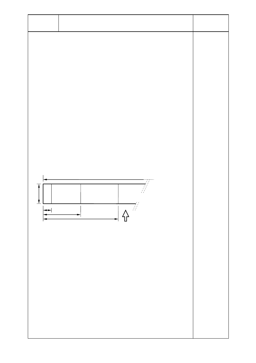
3.5. Friction
forces
3.5.1. Wind on the long side
Total area of the external surfaces parallel to the wind direction:
A
pa
= 2 × 35 × 10 + 120 × 10 = 1900 m
2
Total area of the external surfaces perpendicular to the wind direction:
A
pe
= 2 × 35 × 120 = 8400 m
2
Since A
pa
< 4 A
pe
, the friction forces should not be taken into account.
EN 1991-1-4
§ 5.2(4)
3.5.2. Wind on the gable
Total area of the external surfaces parallel to the wind direction:
A
pa
= 2 × 35 × 120 + 120 × 10 = 9600 m
2
Total area of the external surfaces perpendicular to the wind direction:
A
pe
= 2 × 35 × 10 = 700 m
2
Since A
pa
> 4 A
pe
, the friction forces should be taken into account.
EN 1991-1-4
§ 5.2(4)
2 b = 20 m
4 h = 140 m > 2 b
The friction forces apply on the part of external surfaces parallel to the wind,
located beyond a distance from the upwind edge equal to 20 m. The friction
force F
fr
acts in the wind direction:
EN 1991-1-4
§ 5.2(3)
F
fr
= c
fr
q
p
(z
e
) A
fr
Title
Appendix A Worked Example: Wind action on a multi-storey building
15
of 18
3 - 36
where:
c
fr
= 0,01 for a smooth surface (steel)
q
p
(z
e
) is the peak velocity pressure at the height z
e
as given in Table A.1.
A
fr
is the relevant area.
The results are summarized in Table A.2 for the different strips of the vertical
walls and for the roof.
Table A.2
Friction forces – Wind on the gable
Strip
A
fr
q
p
(z)
F
fr
z
e
m
2
kN/m
2
kN
0 10
m
2000
0,72 14,4
10 m
15 m
1000
0,84
8,4
15 m
20 m
1000
0,92
9,2
20 m
25 m
1000
1,00
10,0
25 m
35 m
1700
1,09
18,5
Parapets 35
m
600
1,09
6,5
Roof 35
m 1000 1,09 10,9
120 m
h
=
35
m
Min(2b ; 4h) = 20m
W
Figure A.6 Friction forces – Wind on the gable
3.6.
Wind forces on surfaces
3.6.1. General
There are three types of wind forces:
Wind forces resulting from the summation of the external and internal
pressure:
(F
w,e
– F
w,i
) / A
ref
= c
s
c
d
q
p
(z
e
) c
pe
– q
p
(z
i
) c
pi
(in kN/m
2
)
They act normally to the surfaces. They are taken as positive values when
they are directed towards the surface and as negative values when they are
directed away from the surface.
Friction forces (see Table A.2)
F
fr
= c
fr
q
p
(z
e
) A
fr
(in kN)
They act on the external surfaces parallel to the wind direction.
Title
Appendix A Worked Example: Wind action on a multi-storey building
16
of 18
3 - 37
Wind forces on parapets
F
w
= c
s
c
d
c
p,net
q
p
(z
e
) A
ref
They act normally to the surfaces.
3.6.2. Wind on the long side
For wind on the long side, the structural factor is: c
s
c
d
= 0,773
Regarding the normal design situation, the values of the resulting pressure are
given in Table A.3 for the vertical walls and the roof:
(F
we
– F
wi
)/A
ref
= c
s
c
d
q
p
(z
e
) c
pe
– q
p
(z
i
) c
pi
where:
c
pe
are the external pressure coefficients determined in § 3.1.1 for the
vertical walls, and in § 3.1.2 for the roof.
q
p
(z
e
) = 1,09 kN/m
2
q
p
(z
i
) =
q
p
(z
e
) = 1,09 kN/m
2
as stated in § 3.3.1
Note that for wind on the long side, there are no friction forces for this
building.
Table A.3
Wind on the long side (kN/m
2
) – Vertical walls
Vertical
walls
Roof
Zone A D E F G H
c
pe
-1,2 +0,8 -0,6 -1,4 -0,9 -0,7
c
pi
= +0,2
-1,23
+0,46
-0,72 -1,40 -0,98 -0,81
c
pi
= -0,3
-0,68
+1,00
-0,18 -0,85 -0,43 -0,26
In Table A.4, the values of the resulting pressure are given for the parapet,
using the formula:
F
w
/A
ref
= c
s
c
d
q
p
(z
e
) c
p,net
where:
c
p,net
are the pressure coefficient determined in § 3.4.1
q
p
(z
e
) = 1,09 kN/m
2
Table A.4
Wind on the long side (kN/m
2
) - Parapet
Zone A B C D
c
p,net
2,1 1,8 1,4 1,2
F
w
/ A
ref
(kN/m
2
)
1,77 1,52 1,18 1,01
Title
Appendix A Worked Example: Wind action on a multi-storey building
17
of 18
3 - 38
Regarding the accidental design situation, the values of the resulting pressure
are given in Table A.5 for the vertical walls and the roof, and for two
situations:
Opening in zone D (c
pi
= +0,7)
Opening in zone A (c
pi
= -1,1)
Table A.5
Wind on the long side (kNm
2
) – accidental design situation
Vertical
walls
Roof
Zone A D E F G H
c
pe
-1,2 +0,8 -0,6 -1,4 -0,9 -0,7
c
pi
= +0,7
-1,77
-0,09
-1,27 -1,94 -1,52 -1,35
c
pi
= -1,1
+0,19
+1,87
+0,69 +0,02 +0,44 +0,61
3.6.3. Wind on the gable
For wind on the gable, the structural factor is: c
s
c
d
= 0,884
Regarding the normal design situation, the values of the resulting pressure are
given in Table A.6 for the vertical walls and in Table A.7 for the roof:
(F
we
– F
wi
)/A
ref
= c
s
c
d
q
p
(z
e
) c
pe
– q
p
(z
i
) c
pi
where:
c
pe
are the external pressure coefficients determined in § 3.1.1 for the
vertical walls, and in § 3.1.2 for the roof
q
p
(z
e
) is the peak velocity pressure in kN/m
2
q
p
(z
i
) =
q
p
(z
e
) for each strip, as stated in § 3.3.1.
Table A.6
Wind on the gable – Vertical walls
Zone
A B C D E
c
pe
-1,2
-0,8
-0,5 +0,7 -0,3
0 < z ≤ 10
-0,91 -0,65 -0,46 +0,30 -0,33
10 < z ≤ 15
-1,06 -0,76 -0,54 +0,35 -0,39
15 < z ≤ 20
-1,16 -0,83 -0,59 +0,39 -0,43
20 < z ≤ 25
-1,26 -0,91 -0,64 +0,42 -0,47
c
pi
= +0,2
25 < z ≤ 33,50
-1,37 -0,99 -0,70 +0,46 -0,51
0 < z ≤ 10
-0,55 -0,29 -0,10 +0,66 +0,03
10 < z ≤ 15
-0,64 -0,34 -0,12 +0,77 +0,03
15 < z ≤ 20
-0,70 -0,37 -0,13 +0,85 +0,03
20 < z ≤ 25
-0,76 -0,41 -0,14 +0,92 +0,03
c
pi
= -0,3
25 < z ≤ 33,50
-0,83 -0,44 -0,15 +1,00 +0,04
Title
Appendix A Worked Example: Wind action on a multi-storey building
18
of 18
3 - 39
Table A.7
Wind on the gable - Roof
Zone F
G
H
I
c
pe
-1,4 -0,9 -0,7 -0,2
c
pi
= +0,2
-1,57 -1,09 -0,89 -0,41
c
pi
= -0,3
-1,02 -0,54 -0,35 +0,13
In Table A.8, the values of the resulting pressure are given for the parapet,
using the formula:
F
w
/A
ref
= c
s
c
d
q
p
(z
e
) c
p,net
Table A.8
Wind on the gable (kN/m
2
) - Parapet
Zone A B C D
F
w
/ A
ref
(kN/m
2
)
2,02 1,73 1,35 1,16
Accidental design situation
Regarding the accidental design situation, the values of the resulting pressure
are given in Table A.9 for the vertical walls and in Table A.10 for the roof,
and for two situations:
Opening in zone D (c
pi
= +0,6) for 25 m ≤ z ≤ 33,50 m
Opening in zone A (c
pi
= -1,1) for 25 m ≤ z ≤ 33,50 m
Table A.9
Wind on the gable (kN/m
2
) – Vertical walls – Accidental design
situation
Zone
A B C D E
c
pi
= +0,6
-1,81 -1,42 -1,13 +0,01 -0,94
c
pi
= -1,1
+0,04 +0,44 +0,72 +1,87 +0,94
Table A.10 Wind on the gable (kN/m
2
) – Roof – Accidental design situation
Zone F
G
H
I
c
pi
= +0,6
-1,99 -1,51 -1,32 -0,84
c
pi
= -1,1
-0,13 +0,34 +0,53 +1,01
Document Outline
- 1 INTRODUCTION
- 2 SAFETY PHILOSOPHY ACCORDING TO EN 1990
- 3 COMBINATIONS OF ACTIONS
- 4 PERMANENT ACTIONS
- 5 CONSTRUCTION LOADS
- 6 IMPOSED LOADS
- 7 SNOW LOADS
- 8 WIND ACTION
- 9 EFFECT OF TEMPERATURE
Wyszukiwarka
Podobne podstrony:
MSB09 Description of simple connection resistance calculator 2010 08 05
Wykład 08.05.2010
wykład 3 08.05.2010, Finanse i rachunkowość, Statystyka
prezentacja 08 05 2010 mrp
2002 08 05
2015 08 05 Dec nr 1 MON Gosp psami służb
2010 08 Tranformator idealny wykład 2
2010 02 05 09;33;36
2010 vol 05 POLITYKA ENERGETYCZNA TURCJI PO ZIMNEJ WOJNIE
2010 08 11 16 29 37
Injurious Plants GTA 08 05 055
loveparade 2010 anlage 05 protokoll ag verkehr 20 10 09
2010 08 Szkoła konstruktorów klasa II
opolczykpl wordpress com 2014 08 05 triumf chrzescijanstwa w
08-05 PAM-Czy jesteście gotowi, ezoteryka
SERWIS 2010.07.05
Wykład 08, 05
EdW 2010 08
więcej podobnych podstron