LEP
4.5.09
-00
Frustrated total reflection / Microwaves
PHYWE series of publications • Laboratory Experiments • Physics • © PHYWE SYSTEME GMBH & Co. KG • D-37070 Göttingen
24509-00
1
Related topics
Transmission, reflection, absorption, refraction, phase veloc-
ity, total reflection, surface waves, frustrated total reflection,
tunnel effect.
Principle
In the first part, the transmission and reflection characteristics
of glass, acrylic glass and metal are studied with a microwave
transmitter-receiver pair and are compared to each other.
In the second part, total reflection of microwaves on a pris-
matic surface is suppressed by bringing a second prism with
the same refractive index close to the first one.
Equipment
Microwave transmitter w. klystron
11740.01
1
Microwave receiver
11740.02
1
Microwave power supply, 220 VAC
11740.93
1
Screen, metal, 300
300 mm
08062.00
2
Glass plate, 200
3004 mm
08204.00
1
Plexiglas plate, 200
2004 mm
11613.00
1
Barrel base -PASS-
02006.55
4
Plate holder
02062.00
1
Supporting block 105
10557 mm
02073.00
2
Prism, synthetic resin
06873.00
2
Digital multimeter
07134.00
1
Screened cable, BNC, l =750 mm
07542.11
1
Adapter, BNC-socket/4 mm plug pair
07542.27
1
Vernier caliper, plastic
03014.00
1
Tasks
1. Determination of the reflecting and transmitting character-
istics of glass, acrylic glass and metal.
2. Observation of the effect of frustrated total reflection and
determination of the transmitted irradiance as a function of
distance d to the prismatic surface. The refractive index of
the prism material can be calculated by determining the
attenuation coefficient
H.
Set-up and procedure
1. To begin with, the reflector voltage of the clystron is adjust-
ed to maximum output (no modulation: “ext” and “
G“). Direct
voltage on the rectifier of the antenna is proportional to the
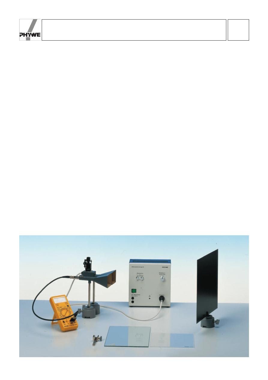
received irradiance. The experimental set-up required to
determine the reflecting characteristics is shown in Fig. 1.
Transmitter and receiver antenna are adjusted to the maxi-
mum reflection signal, for which the distance between the
material plate and the antenna heads should be 40 cm. The
reflecting power of glass, acrylic glass and metal plates
(screen) are then measured.
To determine the transmission characteristics, the directional
receiver is set up at r = 80 cm (distance of the antenna heads)
from the transmitter antenna, in order to compensate the loss
of irradiance in air due to absorption by water molecules and
to the divergence of the emitted microwaves (proportional to
r
– 2
). For comparison, the values of irradiance transmitted
through air should also be noted along with those for irradi-
ance transmitted through the test material.
2. The experiment for frustrated total reflection is shown in
Fig. 2. The microwave transmitter is set up directly in front of
the first prism in such a way, that only one half of the back sur-
face of the prism is irradiated. The other half of the prism is
covered from the back with a screen, in order to protect the
receiver from multiply reflected waves.
Fig. 1: Experimental set-up to determine reflection characteristics.

LEP
4.5.09
-00
Frustrated total reflection / Microwaves
24509-00
PHYWE series of publications • Laboratory Experiments • Physics • © PHYWE SYSTEME GMBH & Co. KG • D-37070 Göttingen
2
The radiation characteristic of the microwave emitted by the
horn antenna is directed forward and similarly the receiver
antenna has the same, narrow reception characteristic. If the
sphere function of the microwave field is developed according
to plane waves, the plane wave propagated in the main radi-
ating direction of the horn antenna is absorbed better by the
receiving antenna than the inclined plane waves, as only this
wave impinges again perpendicularly onto the receiving funnel
after passing the prisms. If the emitted wave is thus approxi-
mated by this plane wave, it impinges on the rear surface of
the prism with an angle of 60 °, and total reflection condition is
fulfilled. By shifting the receiver perpendicularly to the plane of
incidence of the microwaves (which is formed by the direc-
tions of polarization and of radiation of the horn antenna), it
can be verified that the microwave is actually totally reflected
by the second surface of the prism.
The surface of the second prism is then brought into close
contact with the reflecting surface of the first prism. To com-
pensate the offset of the beam, it is recommended to shift the
directional receiver perpendicularly to the plane of incidence
of the microwaves to maximum receiving signal. Using the
Vernier caliper, the relationship between transmitted irradiance
and the distance from the prismatic surface can be measured
in steps of 1 mm (d = 0.1…2.0 cm) It must be particularly
taken care to maintain the parallelism between the two surfac-
es during the procedure.
Theory and evaluation
If a plane electromagnetic wave traveling through medium 1
(n
1
) meets a second medium (2) (n
1
p n
2
), transmission, reflec-
tion and absorption occur (scattering due to material inhomo-
geneity is considered to be negligible). If transmission coeffi-
cient T, reflection coefficient R and absorption coefficient A
are defined by the corresponding partial irradiances I
T
, I
R
and
I
A
of total irradiance I
1
of the incident beam (e. g. T = I
T
/I
1
),
the following relation applies, due to conservation of energy:
T + R + A = 1
(1)
T, R and A are functions of the angle of incidence as well as
of the electronic and atomic characteristics of the material.
Thus, for example, in metals, the valence electrons can move
freely within the solid. The incident electromagnetic wave
excites the electrons into oscillating motion along the E
Field.
Charge carriers thus accelerated (Hertzian dipoles!) produce
an opposite phase wave which has the same frequency: dur-
ing transmission, interference between the primary and sec-
ondary waves is destructive and they annihilate each other.
This is why a large proportion of the irradiance of the incident
wave is reflected in metals, independently from frequency.
Collisions between electrons and lattice disturbances cause
part of the incident radiation energy to be converted to Joule
heat, which means that it is absorbed. The measurement per-
Fig. 2: Experimental set-up for frustrated total reflection.
LEP
4.5.09
-00
Frustrated total reflection / Microwaves
PHYWE series of publications • Laboratory Experiments • Physics • © PHYWE SYSTEME GMBH & Co. KG • D-37070 Göttingen
24509-00
3
formed on the metal screen (table 1) verifies that the micro-
wave is not transmitted, but that a small part is absorbed and
a significantly larger part is reflected. Deviations from this
model occur for wavelengths which are not distinctly larger
than the atomic lattice distances, because the oscillating
amplitudes of the accelerated free electrons are drastically
reduced with increasing frequency.
Non conductors or dielectric materials have no free charge
carriers. However, charge transfers occur in the material in an
electric field, due on the one hand to permanent dipole
momenta which may be present, and on the second to the
shifting of the valence electrons in relation to the molecular
body (induced dipole momentum), whose restoring forces F
can be described as elastic in a first order approximation:
The resulting dipole momentum per unit volume is called di-
electric polarization
and is usually proportional to the
electrical field intensity:
where e = permittivity
e
0
= permittivity of vacuum
The phase shift of the forced oscillations of a damped har-
monic oscillator – and thus also that of the resulting secondary
waves – related to the incident waves depends on the fre-
quency of the exciting waves
W related to the resonance fre-
quency of the oscillator. The result is a strong frequency
dependence of the transmission, reflection and absorption
characteristics of dielectric materials. The transmission and
reflection characteristics of light compared to those of micro-
waves (table 1) for glass as well as for Plexiglas clearly dem-
onstrates this fact. A further consequence of the phase shift of
the secondary waves in relation to the primary waves is the
change of phase velocity (which in turn causes refraction) of
the resulting electromagnetic wave.
P
S e
0
1e 12 E
S
,
P
S
F
S r
S
Tab. 1: Reflection, transmission and 1-reflection-transmission
measurements of different probes.
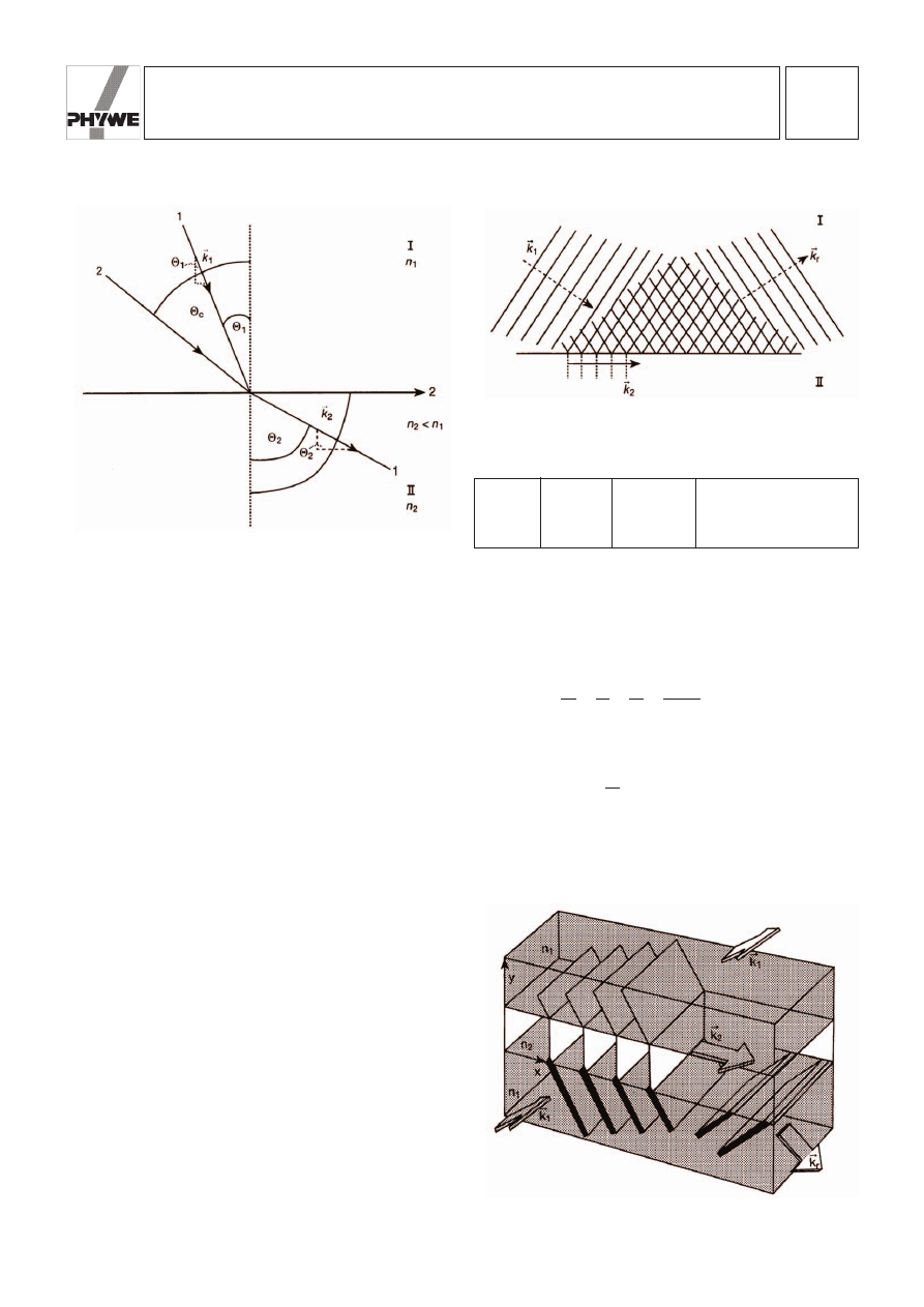
The transmission and reflection coefficients T and R also
depend on the angle of incidence
2
1
of the incident beam (cf.
Fig. 3). A peculiarity occurs during the passage from an opti-
cally dense to an optically thin medium for a large angle
2
1
:
considering Snell’s law (with phase velocity v and wave num-
ber k)
(2)
light with the critical angle of incidence
2
C
= arcsin
(3)
is refracted parallel to the surface (
2
2
= 90 °) and can therefore
not pass into the optically thin medium (cf. Fig. 3). Glass with
n = 1.5 has a critical angle
2
C
of 42 °. Finally, for
2
1
>
2
C
, no
real value for the exiting angle can be determined: the trans-
a
n
2
n
1
b
n
1,2
n
1
n
2
v
2
v
1
k
1
k
2
sin®
1
sin®
2
Reflection
Transmission 1-Reflection-Transmission
Metal
0.88
0.00
0.12
Glass
0.38
0.60
0.02
Plexiglas
0.16
0.83
0.01
Fig. 3: Refraction in an optically thin medium.
Fig. 4: Production of surface waves.
Fig. 5: Frustrated total internal reflection.
LEP
4.5.09
-00
Frustrated total reflection / Microwaves
24509-00
PHYWE series of publications • Laboratory Experiments • Physics • © PHYWE SYSTEME GMBH & Co. KG • D-37070 Göttingen
4
mission condition cannot be fulfilled and the beam is totally
reflected due to conservation of energy (total reflection).
The general wave function of the transmitted wave is:
(4)
With Snell’s law (2) and
the following relation is obtained:
(5)
In case of total reflection (n
12
· sin
2
1
> 1) equation (5) be-
comes:
(6)
with the attenuation coefficient
(7)
g
k
2
2n
12
2
sin
2
®
1
1
E
S
2
1 rS,t2 E
S
0
exp
1gy2 · exp1i1k
2
n
12
sin®
1
x
vt
2 2
E
S
2
1 rS,t2 E
S
0
exp
1i1k
2
n
12
sin®
1
x±k
2
21n
12
2
sin
2
®
1
y
vt
2 2
cos ®
2
±21 sin
2
®
2
E
S
0
exp
1i1k
2
sin®
2
x
k
2
cos®
2
y
vt
2 2
E
S
2
1 rS,t2 E
S
0
exp
1i1 k
S
r
S
vt
2 2
In equation (6), the ‘+’ was left out, because an exponentially
increasing field amplitude makes no sense physically.
The non reflected wave thus travels with the following wave-
length:
along the surface (in e
x
-direction), whereas the electric field
intensity amplitude E
y
decreases exponentially, perpendicular
to the boundary surface (cf. Fig. 4). The wave is thus called a
surface wave. It remains limited mostly to the surface as com-
pared to the wavelength scale.
The surface wave may be “questioned” by a second prism
(n
3
= n
1
). If the distance d between the prismatic surfaces is
small enough to allow the residual field intensity E
2
to induce
oscillating dipole momenta in the molecules of the second
prism, the secondary waves in the second prism can again
travel in the original direction (k
1
) (cf. Fig. 5). In spite of the
condition of total reflection, a part of the incident irradiance is
thus transmitted through the gap in the optically thin medium
and correspondingly reflected to a lesser extent. The field
intensity, and thus the irradiance of the transmitted light,
decreases exponentially with prismatic distance d.
I
trans
= I
0
e
(– 2
H d)
(8)
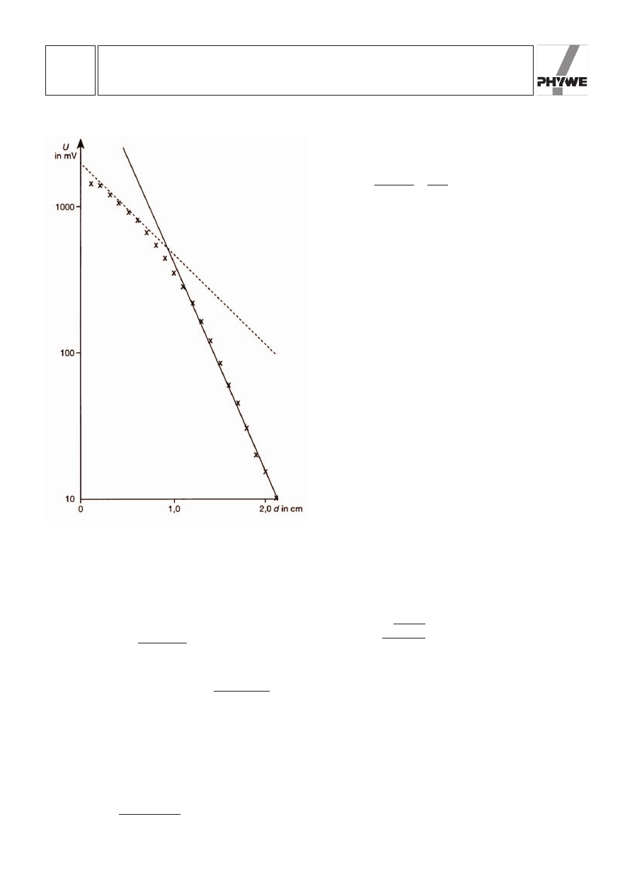
This process is known as frustrated total reflection and is analo-
gous to the tunnel effect of quantum mechanics. Observing the
dependence between transmitted irradiance and prism dis-
tance d on semi-logarithmic paper (cf. Fig. 6), experimental
deviations from exponential decrease are found for irradiance if
distance d is small. This is due to the fact that a microwave
emitted by the horn antenna deviates from a plane wave as well
as to interference between the transmitted wave and the reflect-
ed wave. The attenuation coefficient
H obtained from the full
drawn line (slope between the values of d = 1.0 cm till 2.0 cm),
H = 1.64 cm
–1
yields the following value for the refractive index of synthetic
resin for frequency f = 9.45 GHz:
(9)
with
2
1
, 60 °, n
air
, 1 and k
2
= 2
Qf/c = 1.98 cm
The dotted line on the graph, which represents the lower error
of the refractive index, corresponds to a value of n = 1.23.
The principle exposed above can be used to design radiation
dividers with variable radiating relation. Furthermore, this
experiment clearly shows why glass fiber surfaces must be
free of impurities, in order to minimize losses of light due to
frustrated total reflection.
Caution
Although the clystron only has low power, one must avoid
looking directly into the microwave.
n
12
2k
2
2
g
2
k
2
sin ®
1
1.50
l
2p
k
1
sin ®
1
2p
k
1
, x
Fig. 6: Transmitted radiation intensity as a function of distance.
Wyszukiwarka
Podobne podstrony:
PHYWE P2450800 Radiation field of a horn antenna Microwaves
PHYWE P2450400 Interference of microwaves
PHYWE P2450600 Diffraction and polarization of microwaves
Microwave vacuum drying of marine sediment determination of moisture content, metals and total carbo
Total Quality Management (TQM)
prezentacje, TOTAL QUALITY MANAGEMENT
Microwaves in organic synthesis Thermal and non thermal microwave
components microwave
Gangsterzy i frustraci 2005 test i odp PR
Drying kinetics and drying shrinkage of garlic subjected to vacuum microwave dehydration (Figiel)
Functional improvements desired by patients before and in the first year after total hip arthroplast
Improving Grape Quality Using Microwave Vacuum Drying Associated with Temperature Control (Clary)
Frustracja zawodowy zabojca ebook demo id 181115
więcej podobnych podstron