MULTI BAND HF FAN DIPOLE ANTENNA DESIGN
http://www.hamuniverse.com/multidipole.html
1 z 6
22-07-09 11:54
1024 X 768 Resolution
Best!
SEARCH
About Hamuniverse
Antenna Design
Ask Elmer
About Batteries
Code Practice
Computer Help
Electronics
FCC Information
Ham Hints -
Humor
Ham Radio News!
HF & Shortwave
License Study
Links
Midi Music
Reading Room
Repeater Basics
Repeater Builders
Info
RFI Tips and Tricks
Ham Satellites
Shortwave Listening
SSTV
Support The Site
STORE
Vhf and Up
Contact
Site Map
Privacy Policy
Legal Stuff
BUILD THIS MULTIBAND FAN DIPOLE
FOR ALL BAND HF ANTENNA EXCITEMENT
(NEW UPDATED CONSTRUCTION TIPS FOR FASTER TUNING---SEE
BELOW)
CONSTRUCTION UPDATES FOR EASIER TUNING - 9-08:
Based on research done by the Stanford Research Institute
(SRI) to construct a three-frequency multi-band dipole that
would work without any need for cut and try techniques, we pass
on this information in the hope that it will help you more easily
get this type of antenna on the air quicker.
What they came up with was much improved method over
the old cut and prune technique.
They found that the wires at the center feed point had to be
separated by at least 5 1/2 inches vertically and the ends
separated by 38 inches in the
2 to 18 MHz range.
By this simple change they found that you could accurately cut
the antenna element lengths for given frequencies and eliminate
the need for pruning.
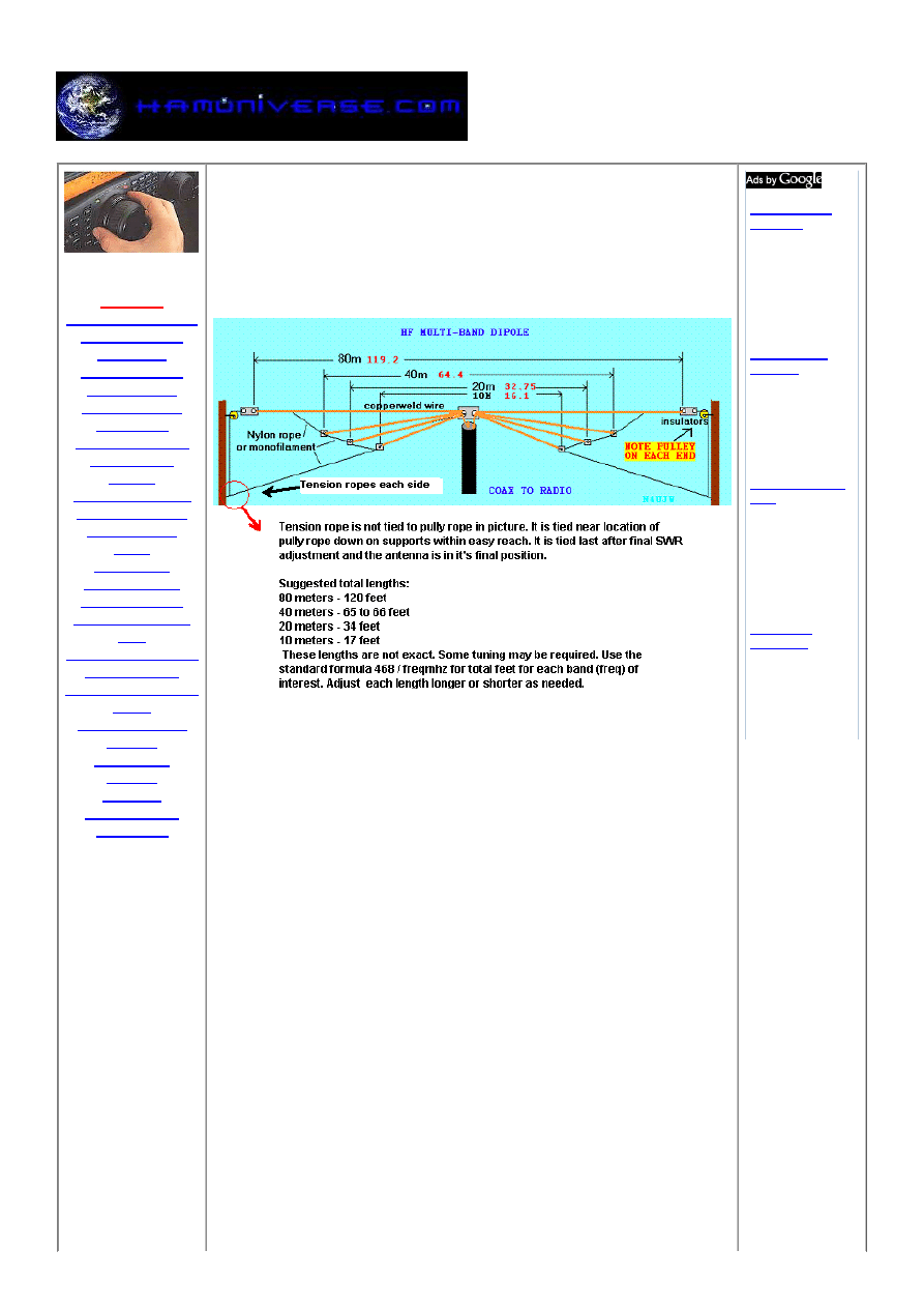
In the drawing above, the lowest frequency antenna is on top
and is cut 4% short of the standard 1/2 wave length. (Length in
feet= 0.96 times 468 divided by the operating frequency in
MHz).
The middle frequency antenna (lower in frequency), is cut for an
Commander II
Amplifier
144 MHz
mono-band HAM
amplifier eham:
"Power house"
Save $100
www.ebay.com
UHF TACSAT
Antenna
Rugged, pistol
grip, lightweight Kit
includes cables,
mounts
www.SyntonicsCorp.com
Auto Tuner 1500
Watt
Auto Antenna
Tuner American
made 3 year
warranty - Built
like a tank
www.palstar.com
Multi Band
Converter
Einkabel lösung
für twin receiver
stacker destacker
OLT unicable
www.johansson.be
MULTI BAND HF FAN DIPOLE ANTENNA DESIGN
http://www.hamuniverse.com/multidipole.html
2 z 6
22-07-09 11:54
exact 1/2 wave length. (length in feet= 468 divided by the
frequency in MHz)
The highest frequency antenna is at the bottom and cut for 1%
longer than the 1/2 wavelength (length in feet= 1.01 times 468
divided by the frequency in MHz)
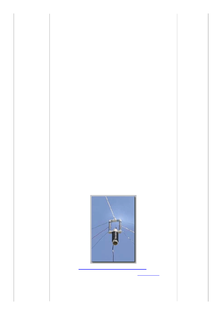
The only construction effort necessary over a standard
multi-band dipole is the fabrication of a feed block or center
insulator that is about 12 inches vertically by 3 inches wide,
made of a good insulating material, such as Lucite, Bakelite,
fiberglass, or PVC.
The end 38 inches of separation can be maintained by separate
halyards on each element or a spreader bar with a common
halyard.
The bandwidth will be at least plus or minus 2% for a 1.5 to 1
SWR according to Stanford Research Institute.
Editors note: It is assumed that this method will only work
as described, if you are working with a "3 band" multiband
dipole. We do not have information for use with over 3
bands. If you arrive at a better method, let us know!
You can chose whichever method of constructing the
multiband dipole using either the method above or use the
old cut and try method below......your choice.
We would appreciate any feedback if you use the newer
method ABOVE!
Email n4ujw at hamuniverse.com with your comments
See how others have built it using the new
method!
http://www.sstowers.com/aa4cv
Cool fan dipole project using the "
Ugly Balun
"!
Older cut and try method below:

MULTI BAND HF FAN DIPOLE ANTENNA DESIGN
http://www.hamuniverse.com/multidipole.html
3 z 6
22-07-09 11:54
CONSTRUCTING THE MULTIBAND DIPOLE: (Older cut
and try method)
Here is a fairly simple and easy to build multi band horizontal fan
type dipole that can be constructed for all band operation from
160 meters up thru 6 meters or even higher.
In the drawing above, it is shown for just four bands, 80 thru 10.
One separate dipole for each band needed. However you can
build it to suit your own preferences by using the standard
formula for a dipole:
468/freq mhz = total length for each band. Use the formula for
your desired center frequency.
Each dipole length above in
RED
is in feet and tenths of a foot
for the center of the General portion of each band
and
is derived
from the above formula and should be cut
longer
for swr
trimming. USE #12 TO #14 GAUGE COPPERWELD WIRE IF
POSSIBLE or use what you have on hand. The top most dipole
must support the entire weight of the antenna.
Start with your lowest (in frequency) band of operation as the
main (top) support for the entire setup. Cut it per the formula but
add a couple of feet on each end for tuning. Try to use a wire
size that will support the other dipoles.
This is the main support for all the other dipoles and must carry
their weight.
Cut a dipole for each band of operation. (SEE EDITORS NOTE
AT BOTTOM OF ARTICLE)
Cut each full length in half....example: for the 10 meter length
from the formula you get 16.1 feet for the total length. Cut it in
half at about 8 feet per side. Make sure you cut each length
about a foot or more longer for swr trimming and attaching to
center and end insulators!
If you are building the four band dipole above, you should have
8 lengths of wire scattered all over your work area.
WARNING! DON'T DO IT IN YOUR LIVING ROOM, THE XYL
WILL NOT BE VERY HAPPY WITH YOU AND AFTER SHE
GETS FINISHED WITH THE QRM,,,, ALL YOUR ANTENNA
BUILDING WILL HAVE TO BE DONE FROM THE DOG'S HAM
SHACK!
It is assumed that you have your end support poles, trees,
center and end insulators, pulleys all ready to go before you
start working on the actual dipoles.
A very important part of this design is the installation of the
pulleys (in yellow on drawing) on each end attached to each side
support.
They are added to this design due to the swr trimming process
and make it very easy to pull the entire antenna up and down
while making the swr adjustments. Mount a suitable size pulley
on each end attached to your pole, trees, etc for the diameter of
cord or rope used to support the system.
Start your antenna trimming with the top dipole.... attach your
coax to the center insulator leaving several inches of the center

MULTI BAND HF FAN DIPOLE ANTENNA DESIGN
http://www.hamuniverse.com/multidipole.html
4 z 6
22-07-09 11:54
conductor and shield exposed. Each half of each dipole will be
connected to the coax center pigtail and the shield separately. In
other words, connect one side of the dipole to the center
conductor and the other side to the shield.
Attach the other end of each half of the longest wire to the
support cord and run thru the pulley on each end and pull the
dipole up into the air between the end supports. Check swr.
Trim as needed with low power for lowest swr possible, lower
with pulleys, attach the next highest band dipole electrically to
the same point as the first dipole, raise it to operating height,
check swr, lower for trimming, up and down, up and
down.........due the same for all other dipoles for each higher
band of operation.
When you are finished with the highest band of operation, pull
the entire system up with the pulleys and tie of at the bottom
securely.
Make certain that the coax center conductor is attached to one
half of each dipole and the shield to the other half. All dipole
ends at center insulator are connected together.
This may not be very clear to the new antenna builder so please
see the drawing below for the center insulator arrangement.
(NOTE: IF USING THE NEWER CONSTRUCTION METHOD MENTIONED ABOVE,
INSURE PROPER SPACING OF ANTENNA LEGS AT THIS CENTER INSULATOR!)
The white areas in the center support drawing above are
mechanical supports, clamps, wire ties or whatever your genius
can come up with to support the main (top wire) and the weight
of the coax.
Remember, all the weight of this antenna system is supported
by the top wire.
The connections should be soldered and all should be sealed
including coax end from water, ice, snow etc.
Use a 1:1 balun like the "
Ugly Balun
" project page on this site
close to the center before coax goes to your rig.
For best performance get it as high as possible and remember
that since this is a dipole arrangement, it will be somewhat
bi-directional towards and away from you as viewed in the
drawing. (BROADSIDE)
Remember that all elements will interact with each other
in the
tuning process and the final setup must be secured so the angle
or distance between each dipole does not change when blowing
in the wind, etc.
The angle or distance between each dipole is not critical but the
final spacing must be maintained!
It will take lots of work (trial and error) in getting each dipole to

MULTI BAND HF FAN DIPOLE ANTENNA DESIGN
http://www.hamuniverse.com/multidipole.html
5 z 6
22-07-09 11:54
the lowest SWR. Just keep TRYING.
It should also be noted that the antenna can be used in an
inverted v fashion but remember the spacing should be secure
in the final operating position. Tune it as in all the above
instructions. You may use a tuner with this antenna un-trimmed
to save a lot of work!
EXPERIMENT! EXPERIMENT! EXPERIMENT!
Editors note:
The multiband fan dipole can be very difficult to tune for lowest
swr in some installations. There are many variables that will
make tuning difficult. Height above ground, sometimes the angle
of each dipole relative to the other dipoles, surroundings , etc. If
you can get the swr to around 2 to 1 or lower for each
band....don't worry too much about it.
(see the newer
construction method above)
You might also consider using a good antenna tuner if you are
having major tuning problems. A 2:1 SWR or lower can be
handled by most builtin tuners in radios.
You might also consider removing HF combinations such as
40/15 meters and 80/30 meters.
For these cases, cut the element for the lower frequency and let
it serve
double duty at the odd harmonic
. In other words, cut the
40 meter element and let it serve also as the 15 meter element
which eliminates the 15 meter section.
Make sure that the distance between all dipole elements does
not change when tuning.
They must be in a fixed position always with some sort of
spacer. In theory, we could fashion a four-wire antenna for the
80, 40, 30, 20, 15 and 10-meter bands.
In practice, it may be difficult to obtain a good match on all
bands.
Since the resonant length of a given element in the presence of
the others is not the same as a dipole by itself, tuning can be a
tedious and difficult procedure. Adjust elements for resonance in
order from lowest frequency to the highest such as in an 80 40
20 10 combo.....start with 80 first.....then go to next higher
frequency dipole.
Always cut each dipole a lot longer than required for each band
to make tuning easier.
Trim as needed for your operating frequency.
All of these bandwidth, adjustment and matching problems are
easily solved with an antenna tuner at the transmitter, feeding
the antenna through 100 feet or less of RG-8 coax.
Please remember to send us feedback if you are using the
newer construction method or if you have any tips you would like
to pass along to others that make the multiband dipole easier or
faster to get set up! 73!
BACK TO ANTENNA LAB

MULTI BAND HF FAN DIPOLE ANTENNA DESIGN
http://www.hamuniverse.com/multidipole.html
6 z 6
22-07-09 11:54
Powered by Ham Radio!
Copyright 2000 - 2009 Hamuniverse.com or article author - All rights reserved.
Wyszukiwarka
Podobne podstrony:
2 m70 cm Vertical Dipole Antennaid 513
antenna design
HF Antenna Cookbook
Design and construction of three phase transformer for a 1 kW multi level converter
IARU Region1 HF band plan 2011
Wyklad 9 Post HF
multi demultiplekser
wyklad 1 hf
Popular Mechanics Repairing Power Antennas
LG MULTI V
BAND 1 22
History Costume History Costume Design Viking Women
HF 91110 80 Amp Inverter Arc Welder
Gdy coś we mnie umiera, Fan Fiction, Dir en Gray
Sweet, Fan Fiction, Dir en Gray
Zagu
więcej podobnych podstron