
Initial Print Date: 12/04
Table of Contents
Subject
Page
MRS I . . . . . . . . . . . . . . . . . . . . . . . . . . . . . . . . . . . . . . . . . . . . . . . . . . . . . . .4
MRS II . . . . . . . . . . . . . . . . . . . . . . . . . . . . . . . . . . . . . . . . . . . . . . . . . . . . .5
MRS III . . . . . . . . . . . . . . . . . . . . . . . . . . . . . . . . . . . . . . . . . . . . . . . . . . . . . .5
MRS IV . . . . . . . . . . . . . . . . . . . . . . . . . . . . . . . . . . . . . . . . . . . . . . . . . . . . .6
MRS 4RD . . . . . . . . . . . . . . . . . . . . . . . . . . . . . . . . . . . . . . . . . . . . . . . . . . .6
Overview of MRS Features . . . . . . . . . . . . . . . . . . . . . . . . . . . . . . . . . . . . . .7
MRS I System Overview . . . . . . . . . . . . . . . . . . . . . . . . . . . . . . . . . . . . . . . . .8
MRS I System Summary . . . . . . . . . . . . . . . . . . . . . . . . . . . . . . . . . . . . . . . .9
MRS II System Overview . . . . . . . . . . . . . . . . . . . . . . . . . . . . . . . . . . . . . . .10
MRS II System Summary . . . . . . . . . . . . . . . . . . . . . . . . . . . . . . . . . . . . . . .11
MRS III System Overview . . . . . . . . . . . . . . . . . . . . . . . . . . . . . . . . . . . . . .12
MRS III System Summary . . . . . . . . . . . . . . . . . . . . . . . . . . . . . . . . . . . . . .13
MRS IV System Overview . . . . . . . . . . . . . . . . . . . . . . . . . . . . . . . . . . . . . .14
MRS IV System Summary . . . . . . . . . . . . . . . . . . . . . . . . . . . . . . . . . . . . . .15
MRS 4RD System Overview . . . . . . . . . . . . . . . . . . . . . . . . . . . . . . . . . . . .16
MRS 4RD System Summary . . . . . . . . . . . . . . . . . . . . . . . . . . . . . . . . . . .17
Airbag Module Summary . . . . . . . . . . . . . . . . . . . . . . . . . . . . . . . . . . . .20
Side Impact Sensor . . . . . . . . . . . . . . . . . . . . . . . . . . . . . . . . . . . . . . . . . . . .21
B-Pillar Satellite (MRS 4RD Only) . . . . . . . . . . . . . . . . . . . . . . . . . . . . . . .23
Door Pressure Sensors (MRS 4RD only) . . . . . . . . . . . . . . . . . . . . . . . . .23
Up-Front Sensors (MRS 4RD Only) . . . . . . . . . . . . . . . . . . . . . . . . . . . . .24
Seat Occupancy Detection (all except E83) . . . . . . . . . . . . . . . . . . . . . . .25
Seat Occupant Detection OC-3 (E83) . . . . . . . . . . . . . . . . . . . . . . . . . . .26
Airbag Warning Lamp (AWL) . . . . . . . . . . . . . . . . . . . . . . . . . . . . . . . . . . . .31
Airbag Wiring and Connectors . . . . . . . . . . . . . . . . . . . . . . . . . . . . . . . . . .32
Battery Safety Terminal . . . . . . . . . . . . . . . . . . . . . . . . . . . . . . . . . . . . . . . .34
Drivers Airbag . . . . . . . . . . . . . . . . . . . . . . . . . . . . . . . . . . . . . . . . . . . . . . . . .36
Airbag Contact Ring . . . . . . . . . . . . . . . . . . . . . . . . . . . . . . . . . . . . . . . . . . .37
Passenger Airbag . . . . . . . . . . . . . . . . . . . . . . . . . . . . . . . . . . . . . . . . . . . . . .38
Side Airbag . . . . . . . . . . . . . . . . . . . . . . . . . . . . . . . . . . . . . . . . . . . . . . . . . . .38
Multiple Restraint Systems (MRS I - MRS 4RD)
Revision Date:

Subject
Page
Rear HPS . . . . . . . . . . . . . . . . . . . . . . . . . . . . . . . . . . . . . . . . . . . . . . . . . .40
Head Airbag (Curtain Airbag) . . . . . . . . . . . . . . . . . . . . . . . . . . . . . . . . .41
Seatbelt Tensioning Systems . . . . . . . . . . . . . . . . . . . . . . . . . . . . . . . . . . .43
Pyrotechnic Seatbelt Tensioners . . . . . . . . . . . . . . . . . . . . . . . . . . . . . .44
Seat Integrated Belt Systems (SGS) . . . . . . . . . . . . . . . . . . . . . . . . . . .45
Crash Output Signal . . . . . . . . . . . . . . . . . . . . . . . . . . . . . . . . . . . . . . . . . . .48
Fuel Pump Cutoff Circuit . . . . . . . . . . . . . . . . . . . . . . . . . . . . . . . . . . . . . . .49
SOS/Emergency Call . . . . . . . . . . . . . . . . . . . . . . . . . . . . . . . . . . . . . . . . . .50

3
Multiple Restraint Systems (MRS I - MRS 4RD)
Multiple Restraint Systems (MRS I - MRS 4RD)
Model: E36, E38, E39, E46, E53, E52 and E83
Production: All with MRS I, II, III, IV and 4RD
After completion of this module you will be able to:
• Understand the History of MRS System in BMW Group Vehicles
• Identify MRS System components
• Understand MRS system operation
• Diagnose faults in MRS Systems
MRS Systems
MRS was introduced as an enhancement of the existing ZAE system. The main
improvement was the addition of side airbags with side impact sensors. Also, subse-
quent versions of MRS introduced such new technology as Head Protection Systems,
Battery Safety Terminal, 2 Stage (SMART) airbags and later the introduction of the curtain
airbag on the E83.
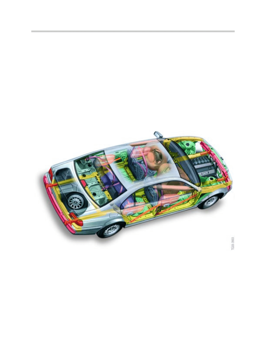
MRS I
The first version of MRS (MRS I) was introduced with the E39 in March of 1996 and also
added to the E38. This system was the first BMW passive safety system to use side
airbags with remotely mounted side impact sensors. MRS I remained in use on some
models until 9/97 production.
4
Multiple Restraint Systems (MRS I - MRS 4RD)
E39 with MRS II
MRS II
This system was introduced into production vehicles from 5/97 until 9/99. The Head
Protection System (HPS) became a standard feature and the option of rear side airbags
were also made available. The 2-Stage passenger side airbag was added in September
of 1998 and the Safety Battery Terminal (SBK/BST) was also added to protect the vehicle
from short circuits to the main battery cable.
MRS III
The 2-stage driver’s airbag was one of the new items to be introduced with MRS III.
Another new innovation was the connection of the MRS module to the K-bus for diagno-
sis and output of the “crash signal”. The K-bus connection also allows the MRS III sys-
tem to send a fuel pump cutoff signal to the DME. The only exception is the Z3 (E36/7)
which does not use the K-bus.
5
Multiple Restraint Systems (MRS I - MRS 4RD)
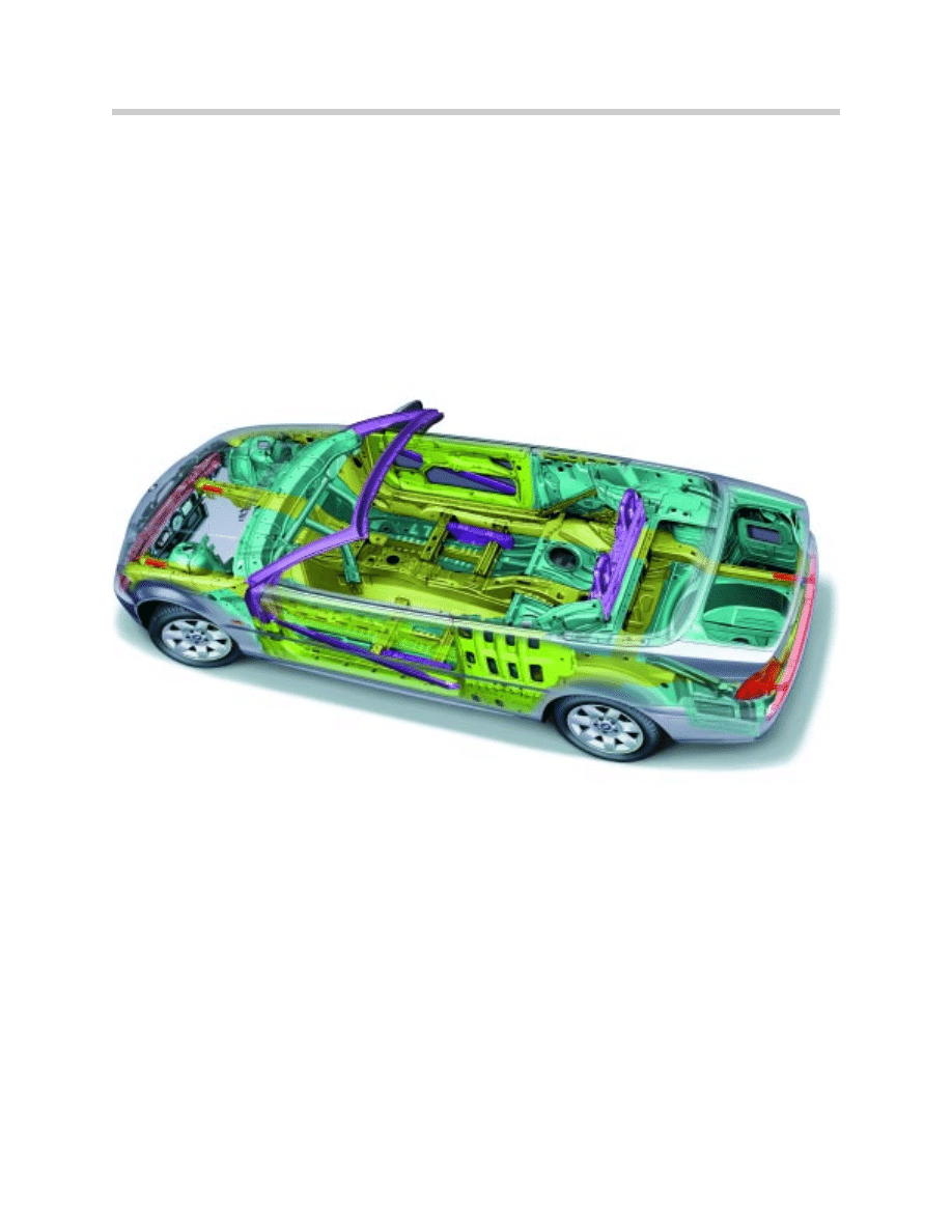
E46 convertible showing reinforced body structures
MRS IV
April of 2001 saw the introduction of MRS IV to the E46 and E53. MRS IV was later
phased into production on the E38 and E39 from 8/01. The primary change was intro-
duction of a modified processor with upgraded software for triggering algorithms.
Otherwise, all of the features and functions from MRS III are carried over to MRS IV.
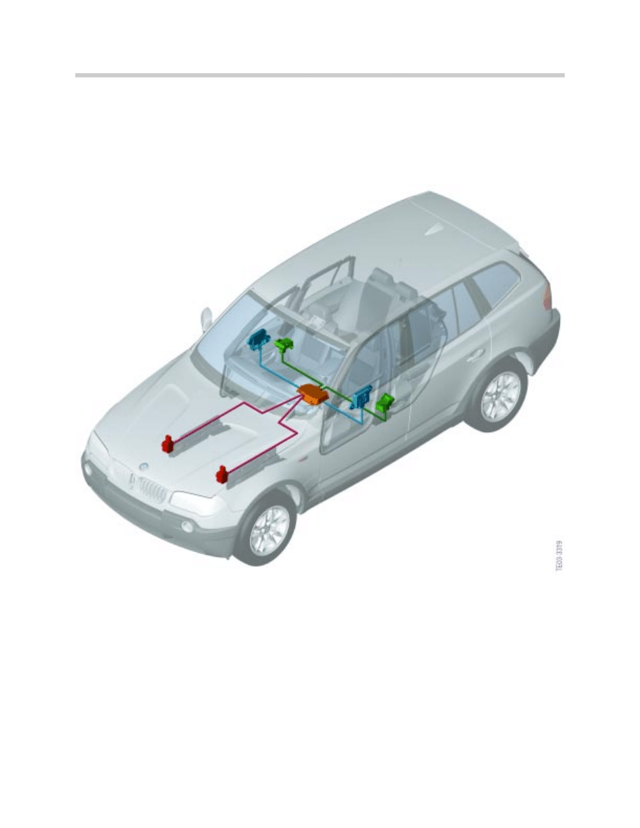
MRS 4RD
The designation “RD” stands for Redesign of the MRS 4 System. The control module
has been upgraded to 75 pins to accommodate new systems and interfaces.
The MRS 4RD system has been optimized with new “up-front” sensors, door compres-
sion sensors and b-pillar satellites.
The system also incorporates the new OC-3 Seat occupancy detection system which
was introduced on the E60. This system has the capability to automatically turn off the
passenger side airbag by detecting the approximate weight and size of the occupant.
6
Multiple Restraint Systems (MRS I - MRS 4RD)
E83 with MRS 4RD

Overview of MRS Features
7
Multiple Restraint Systems (MRS I - MRS 4RD)
MRS
System/
Vehicle
Side airbags with Side
Sensors
Pyr
ot
echnic Seatbelt
Tensioners
HPS F
ront
HPS R
ear
HPS Curtain
Saf
ety
B
att
ery
Cable
(BS
T)
K-B
us Connection
Up-fr
ont
Sensors
Door
Compr
ession
Sensors
B-Pillar
Sat
ellit
es
P
assenger
Seat
Occupancy
Det
ection
2-Stage Airbags
P
assenger
Side
2-Stage Airbag Driv
er’s
Side
MRS I
E39/E38/E36
X
X
X
MRS II
E39/E38/E46
X
X
X
X
MRS II E36
X
X
X
X
MRS III
E38/E39/E53/
E52
X
X
X
OPT
E38
E39
X
X
X
X
9/98
MRS III E46
(Bosch)
X
X
X
X
X
X
X
X
3/99
MRS IV
E38/E39/E46/
E52/E53
X
X
X
OPT
E38
E39
X
X
X
X
X
MRS 4RD
E83
X
X
X
X
X
X
X
X OC-3
X
X
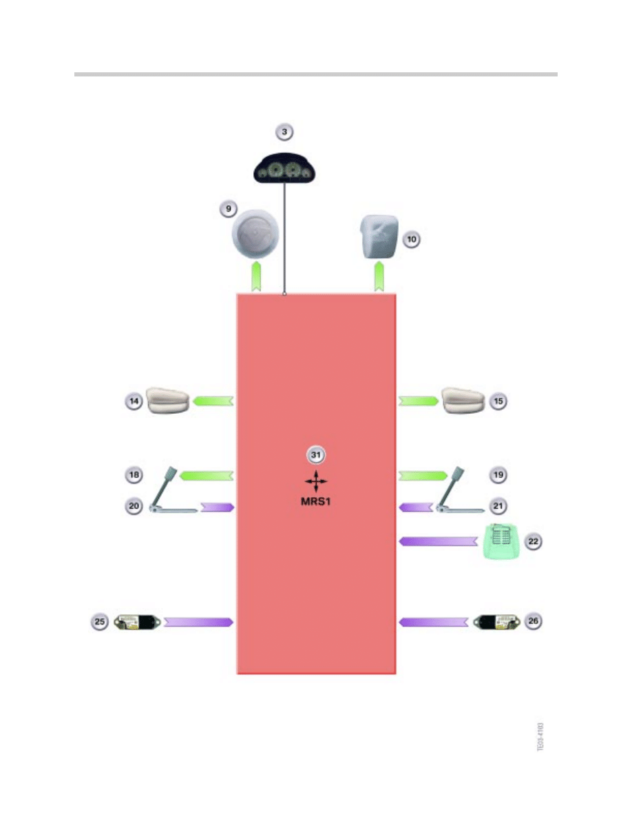
MRS I System Overview
8
Multiple Restraint Systems (MRS I - MRS 4RD)

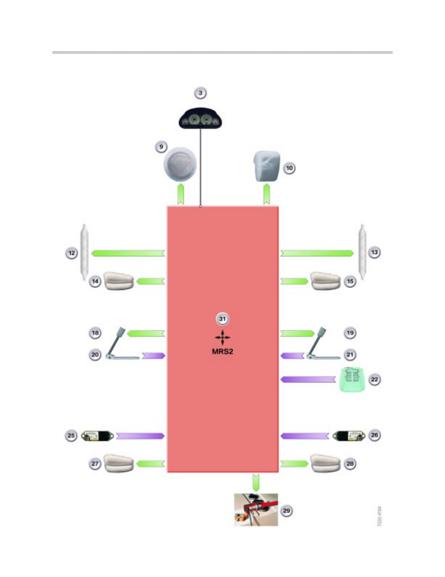
MRS I System Summary
• Introduced on the E39 in the 1997 Model Year (96 Production)
• Side airbags with Side airbag sensors
• Passenger seat occupancy detection (SBE)
• Uses pyrotechnic tensioners
• Diagnosis through TXD/RXD
• Control Module is ZCS codeable
• Uses 50 Pin Control Module
• Crash Output signal (to ZKE and LCM)
9
Multiple Restraint Systems (MRS I - MRS 4RD)
Index
Explanation
3
Airbag warning lamp in instrument cluster
9
Front airbag, driver
10
Front airbag, passenger
14
Side airbag, front left
15
Side airbag, front right
18
Seal belt tensioner, left
19
Seat belt tensioner, right
20
Seat belt buckle switch, left
21
Seat belt buckle switch, right
22
Seat occupancy detector (SBE)
25
MRSA, left
26
MRSA, right
31
Control unit
CA
Crash output
TXD
Diagnostic line
KL R
Terminal R
MRS II System Overview
10
Multiple Restraint Systems (MRS I - MRS 4RD)

MRS II System Summary
MRS II utilizes all of the systems and features of MRS I with the addition of:
• Optional Head Protection System
• Battery Safety Terminal (BST)
• 2-Stage airbag (passenger side from 9/98)
• Uses 50 Pin Control Module (transparent connector)
11
Multiple Restraint Systems (MRS I - MRS 4RD)
Index
Explanation
3
Airbag warning lamp in instrument cluster
9
Front airbag, driver
10
Front airbag, passenger
12
Head airbag, left (ITS)
13
Head airbag, right (ITS)
14
Side airbag, front left
15
Side airbag, front right
18
Seal belt tensioner, left
19
Seat belt tensioner, right
20
Seat belt buckle switch, left
21
Seat belt buckle switch, right
22
Seat occupancy detector (SBE)
25
MRSA, left
26
MRSA, right
27
Side airbag, rear left
28
Side airbag, rear right
31
Control unit
CA
Crash output
TXD
Diagnostic line
KL R
Terminal R
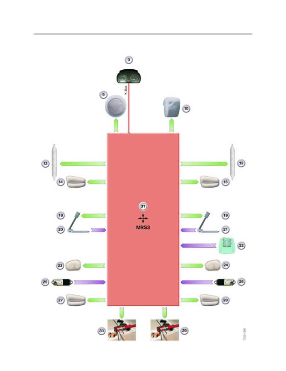
MRS III System Overview
12
Multiple Restraint Systems (MRS I - MRS 4RD)

MRS III System Summary
MRS III uses all of the systems and features of MRS I and II with the addition of:
• 2-Stage airbag, front driver’s side
• Connected to K-Bus (except E6/7)
• Diagnosis via K-Bus (except E36/7)
• Crash output signal via K-Bus (except E36/&)
• Fuel Pump cutoff via K-Bus (to DME via CAN) (except E36/7)
• Optional Rear Head Protection (Rear HPS)
13
Multiple Restraint Systems (MRS I - MRS 4RD)
Index
Explanation
3
Airbag warning lamp in instrument cluster
9
Front airbag, driver
10
Front airbag, passenger
12
Head airbag, left (ITS)
13
Head airbag, right (ITS)
14
Side airbag, front left
15
Side airbag, front right
18
Seatbelt tensioner, left
19
Seat belt tensioner, right
20
Seat belt buckle switch, left
21
Seat belt buckle switch, right
22
Seat occupancy detector (SBE)
25
MRSA, left
26
MRSA, right
27
Side airbag, rear left
28
Side airbag, rear right
29
Safety battery terminal (BST/SBK)
30
Safety battery terminal (BST/SBK)
31
Control unit
CA
Crash output
TXD
Diagnostic line
KL R
Terminal R
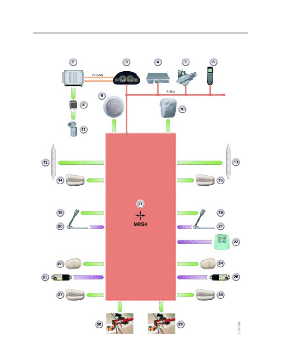
MRS IV System Overview
14
Multiple Restraint Systems (MRS I - MRS 4RD)

MRS IV System Summary
MRS IV uses all of the system and features of MRS I to MRS III with the addition of:
• Modified processor with new software for calculating the triggering algorithm
• Introduced into production on the E46 and E53 in 4/01.
• Phased into the E38 and E39 in 8/01
15
Multiple Restraint Systems (MRS I - MRS 4RD)
Index
Explanation
2
DME control unit (ECM)
3
Airbag warning lamp in instrument cluster
4
Base module (General Module)
5
Light switch cluster
6
Telephone
8
Fuel pump relay
9
Front airbag, driver
10
Front airbag, passenger
11
Electric fuel pump
12
Head airbag, left (ITS)
13
Head airbag, right (ITS)
14
Side airbag, front left
15
Side airbag, front right
18
Seatbelt tensioner, left
19
Seat belt tensioner, right
20
Seat belt buckle switch, left
21
Seat belt buckle switch, right
22
Seat occupancy detector (SBE)
23
Head airbag, rear left
24
Head airbag, rear right
25
MRSA, left
26
MRSA, right
27
Side airbag, rear left
28
Side airbag, rear right
29
Safety battery terminal (BST/SBK)
30
Safety battery terminal (BST/SBK)
31
Control unit
CA
Crash output
KL R
Terminal R
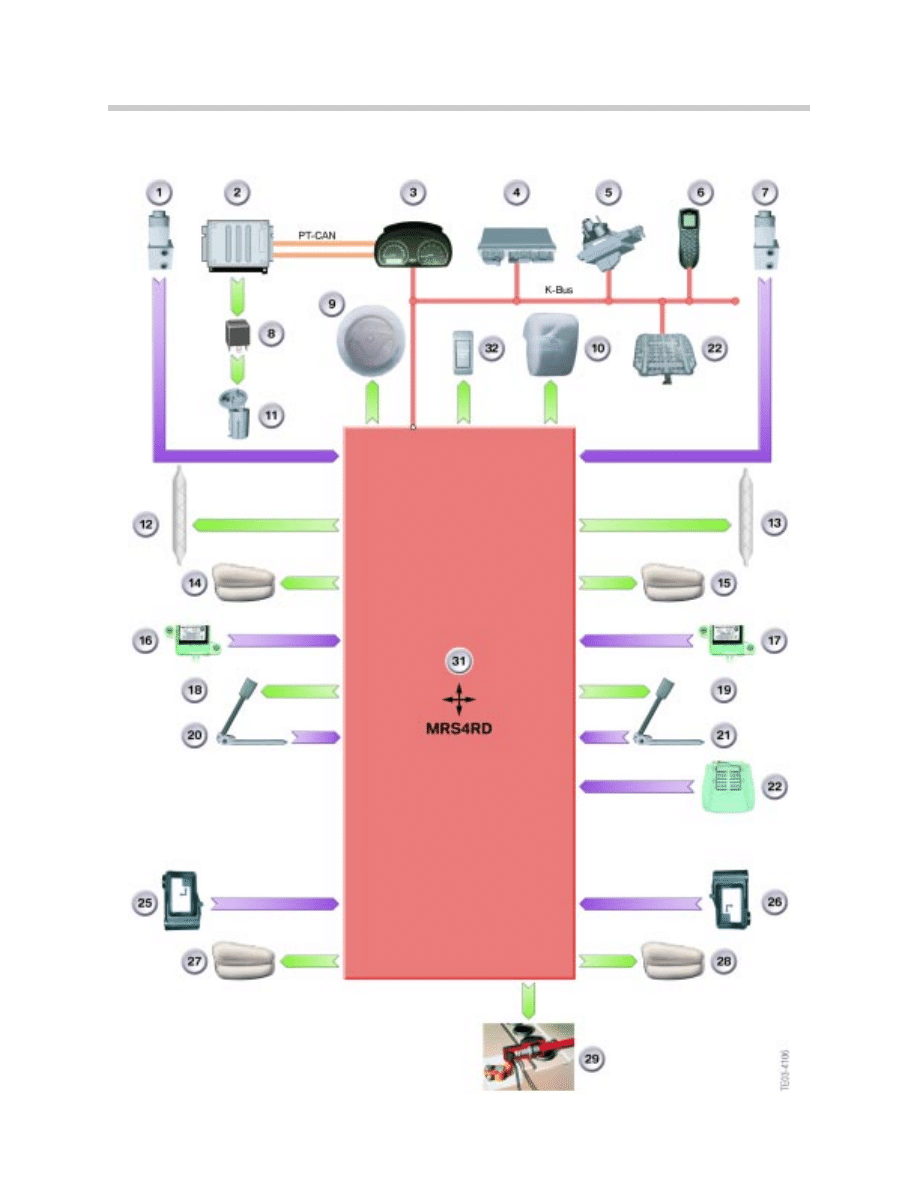
MRS 4RD System Overview
16
Multiple Restraint Systems (MRS I - MRS 4RD)

MRS 4RD System Summary
MRS IV uses all of the system and features of MRS I to MRS IV with the addition of:
• Introduced on the E83 (2004)
• 75 Pin Control Module with integrated acceleration sensors on X and Y axis.
• Control Module is coded/programmed via CIP
• Utilizes door pressure sensors
• Up-front sensors
• B-pillar satellites
• OC-3 Passenger seat occupancy detection with “Passenger Airbag OFF” indicator
17
Multiple Restraint Systems (MRS I - MRS 4RD)
Index
Explanation
1
Airbag sensor, front left
2
DME control unit (ECM)
3
Airbag warning lamp in instrument cluster
4
Base module (General Module)
5
Light switch cluster
6
Telephone
7
Airbag sensor, front right
8
Fuel pump relay
9
Front airbag, driver
10
Front airbag, passenger
11
Electric fuel pump
12
Head airbag, left (ITS)
13
Head airbag, right (ITS)
14
Side airbag, front left
15
Side airbag, front right
16
Door pressure sensor, front left
17
Door pressure sensor, front right
18
Seatbelt tensioner, left
19
Seat belt tensioner, right
20
Seat belt buckle switch, left
21
Seat belt buckle switch, right
22
Seat occupancy detector (SBE)
25
MRSA, left
26
MRSA, right
27
Side airbag, rear left
28
Side airbag, rear right
29
Safety battery terminal (BST/SBK)
30
Safety battery terminal (BST/SBK)
31
Control unit
32
Indicator lamp for front passenger airbag deactivation
CA
Crash output
KL R
Terminal R
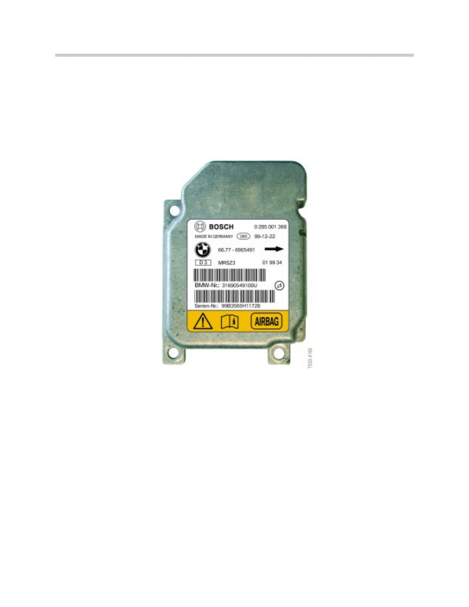
Components
Control Module
The MRS control module is centrally located within the vehicle, usually under the center
console or rear seat. It contains the crash sensing elements as well as the triggering
electronics. The MRS module is also capable of storing up to 10 faults and can be diag-
nosed through TXD or K-Bus (depending upon version).
The MRS control unit is responsible for the following functions:
• Crash Identification
• Crash evaluation and triggering of relevant output devices (pyrotechnic devices)
• Performing Self-Check and System Fault Detection
• Display and storage of faults in Non-Volatile Memory (up to 10 faults stored)
• Fault diagnosis through diagnostic link (D-bus, TXD, RXD) (K-Bus from MRS III)
• Control of operation of the Airbag Warning Light (AWL)
• Vehicle specific coding(through ZCS, CIP)
• Activation of crash output signal
• Fuel Pump Cutoff (from MRS III)
18
Multiple Restraint Systems (MRS I - MRS 4RD)
MRS Control Module
(MRS III Shown)
19
Multiple Restraint Systems (MRS I - MRS 4RD)
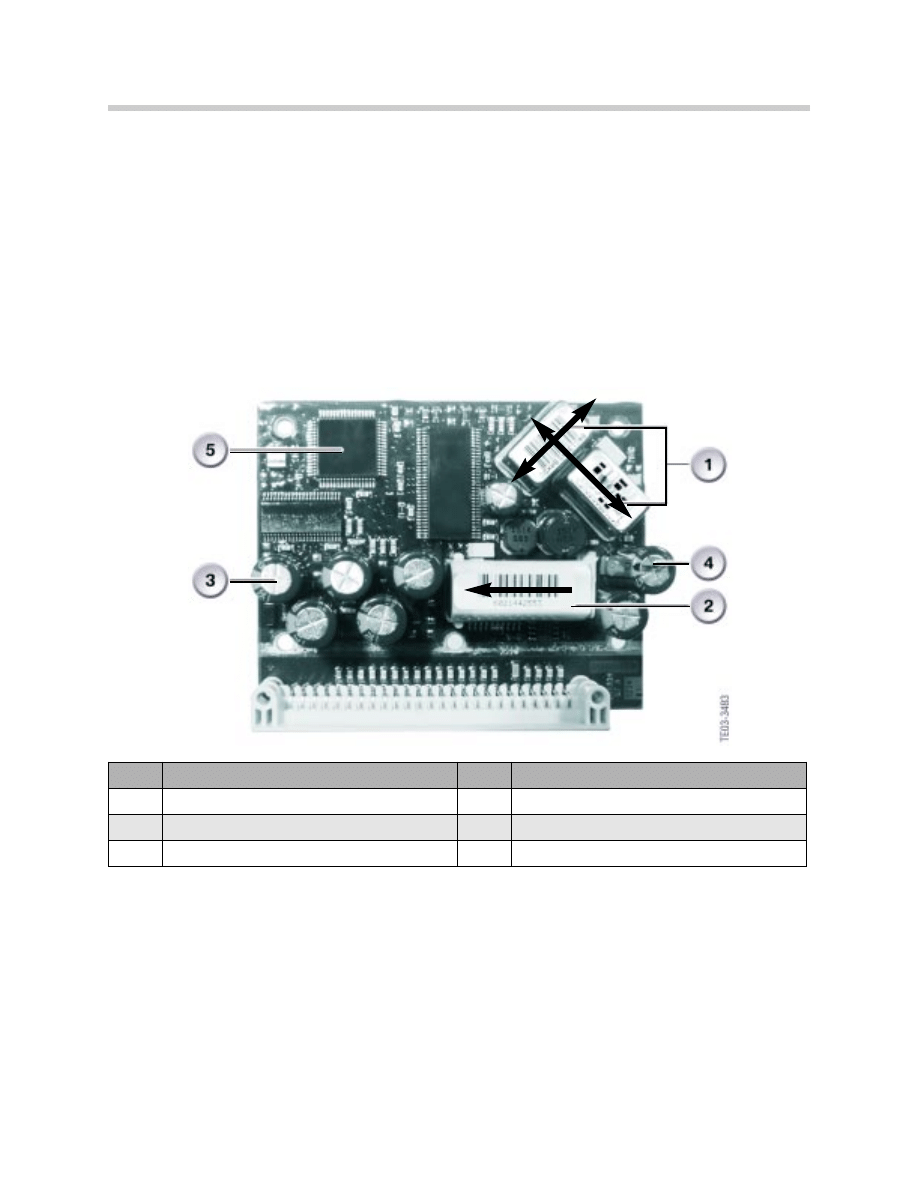
All MRS control modules contain internally mounted crash sensors. There are 2 piezo-
electronic accelerometers and 1 mechanical safing sensor. The accelerometers are
mounted on the circuit board and offset by 90 degrees. Each accelerometer is posi-
tioned 45 degrees from the vehicle centerline which, in combination with the side airbags
sensors, allows for 360 degrees of monitoring capability. The only exception is the
MRS 4RD control unit in which the accelerometers are mounted at 0 and 90 degrees
from the centerline of the vehicle.
The mechanical safing sensor uses a small weight which is counteracted by a spring.
During an impact, the weight overcomes the spring and makes contact to signal an
impact. When an impact is detected by the accelerometers, the airbags will only be
deployed if the safing sensor has been triggered.
The airbag module also contains capacitors for energy reserve in the event of power loss
during a collision. There are 2 sets of capacitors in use. One set is used for the control
module energy reserve and the other is used for the airbag ignition circuit.
The airbag module is capable of storing up to 10 faults in a non-volatile fault memory. Up
to 3 impacts can be detected, after which the module will store a non-erasable fault code.
Once 3 impacts have been detected, the module must be replaced.
Note: Be sure to code the module after installation.
Index
Explanation
Index
Explanation
1
Impact detection sensors
4
Ignition capacitors with igniter output stages
2
Mechanical safety sensor
5
Microprocessor
3
Reserve power capacitor with transformer
MRS Control Module
Internal View (MRS I)
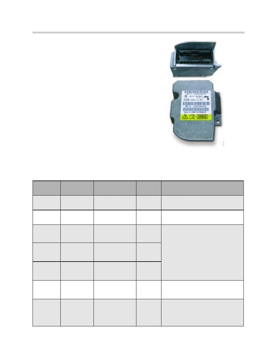
Airbag Module Summary
Airbag modules between systems are not
interchangeable due to hardware and software
differences. Most of the early systems use a
50-pin control module, but use different color
connectors.
The MRS 4RD system uses a 75-pin module
due to additional sensors and peripheral com-
ponents. Also, the internal acceleration sen-
sors are configured differently. They are
installed at 0 and 90 degrees from the vehicle
centerline.
Airbag modules should be installed with the
directional arrow facing the front of the vehicle
unless otherwise noted. Be sure to observe
proper torque specifications during installation.
Note: When servicing airbag systems, always disconnectthe battery before attempt-
ing any repairs. On vehicles produced before 9/93, disconnect battery and wait
at least 30 minutes before starting work. On vehicle produced from 9/93 to pre-
sent, disconnect battery and wait at least 1 minute before starting work.
20
Multiple Restraint Systems (MRS I - MRS 4RD)
System
Manufacturer
Pins/Connector Diagnosis
Comments/Misc
MRS I
Temic
50-Pin/Orange
TXD/RXD
Crash Output Signal, SBE
MRS II
Temic
50-Pin/Transparent TXD/RXD
Crash Output Signal, 2-Stage
Passenger Airbag, SBE, SBK, HPS
MRS III
(E46)
Bosch
50-Pin/Grey
K-Bus
Crash Output Signal, 2-Stage Driver’s
Airbag, SBE, SBK, HPS, Micro-
Mechanical Safing Sensor (Bosch),
Fuel Pump Cutoff (except E36/7)
MRS III
Temic
50-Pin Green
K-Bus
MRS III
(E36/7)
Temic
50-Pin Green
TXD/RXD
MRS IV
K-Bus
Modified processor and new software
for calculating triggering algorithm
MRS 4RD
Temic
75-Pin
K-Bus
Up-front Sensors, Door pressure sen-
sors, B-pillar satellites, OC-3 with pas-
senger airbag de-activation light, modi-
fied internal acceleration sensors
MRS 4RD
Shown
21
Multiple Restraint Systems (MRS I - MRS 4RD)
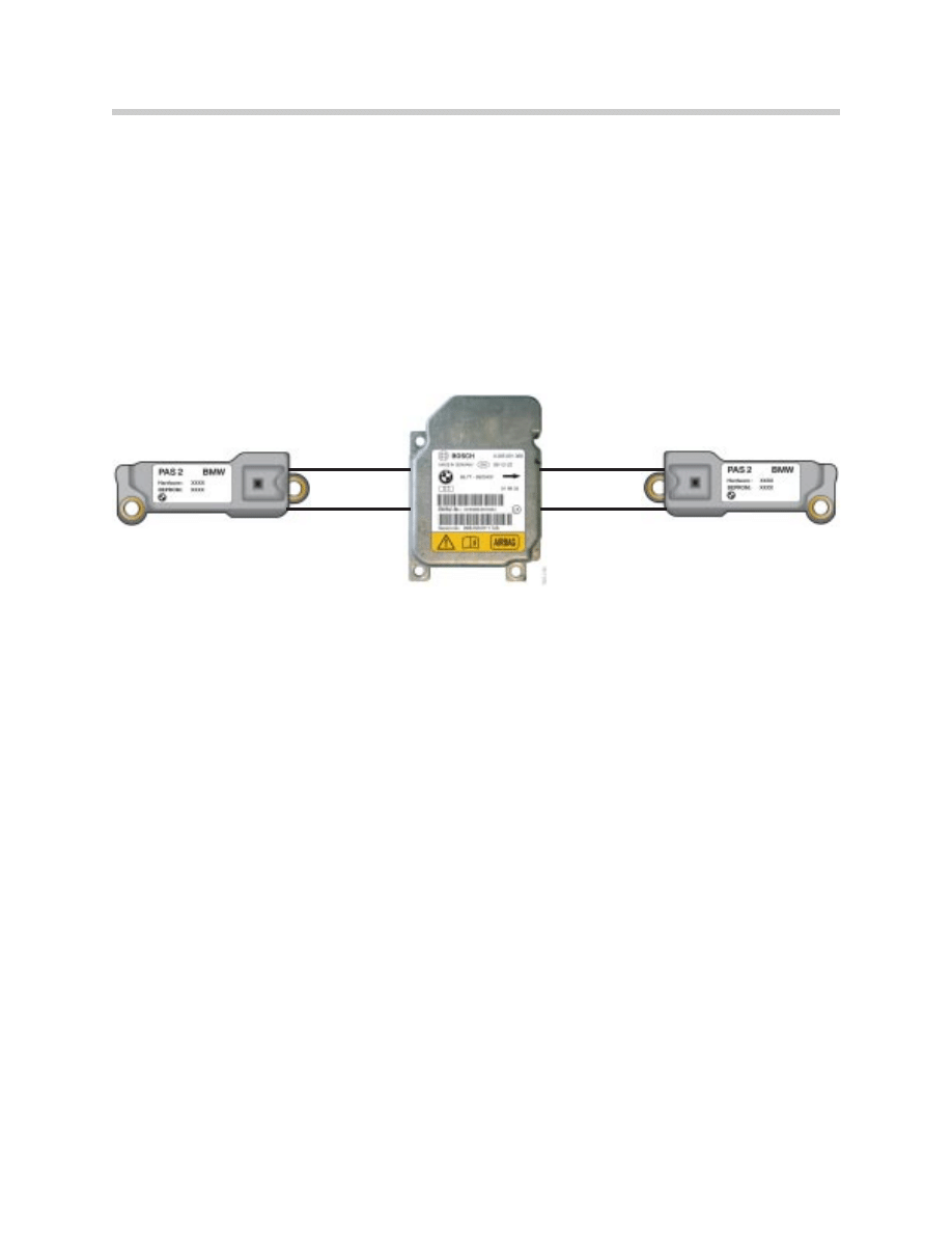
Side Impact Sensor
In order to record side impacts, the MRS system employs a pair of lateral acceleration
sensors referred to as MRSA. These sensors are piezo-electric (accelerometers) sensors
which are mounted perpendicular to the centerline of the vehicle. Usually under the front
seat supports or mounted in the b-pillar area.
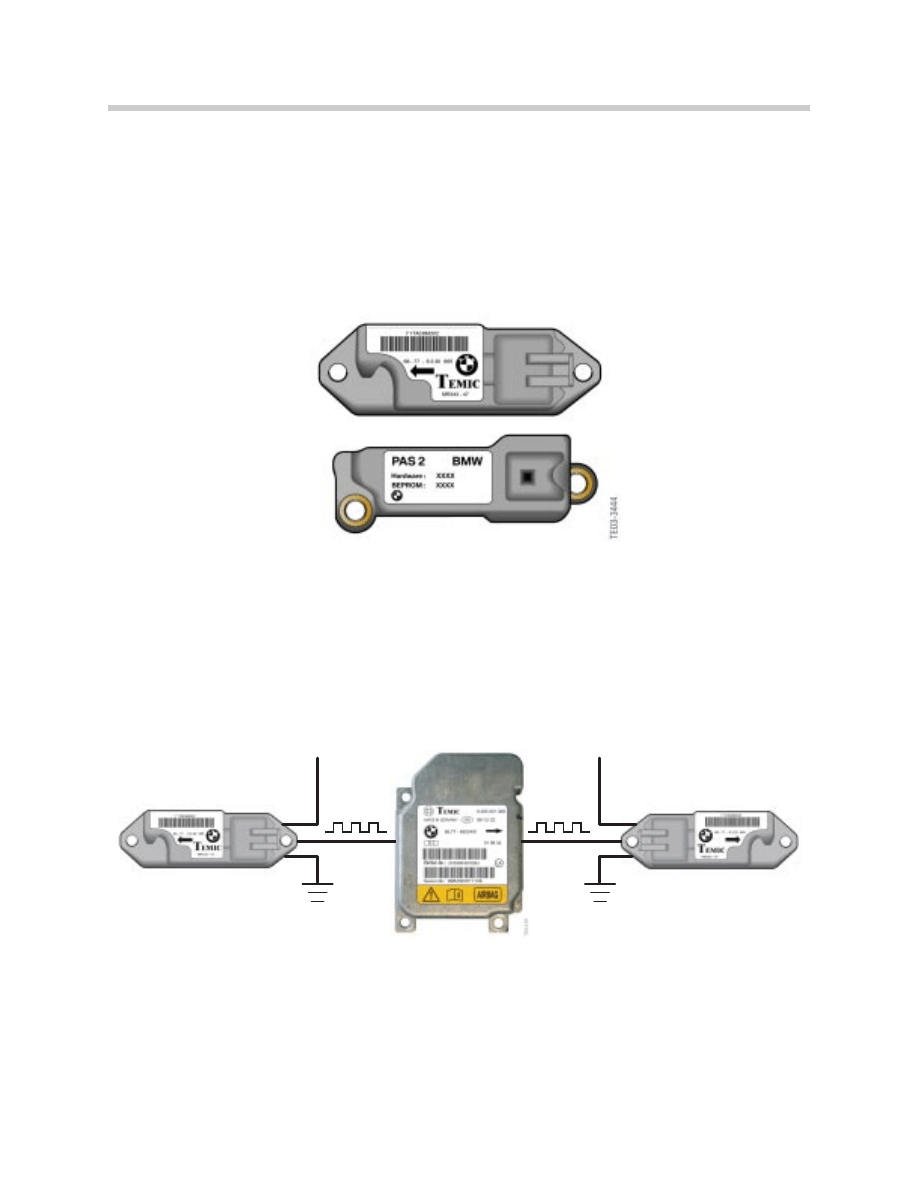
Depending upon application, the side airbag sensors are made by Bosch or Temic. They
are not interchangeable.
On MRS1 and MRS 2 systems the side airbag sensors were manufactured by Temic.
The connector has 3 pins, one for ground (KL31), one for power (KLR), and the third pin
was for the crash signal to the MRS module.
MRS Module
(MRS I / MRS II)
Side Airbag
Sensor (Left)
Side Airbag
Sensor (Right)
Crash
Signal
KLR
KLR
Crash
Signal
MRS3 and MRS 4 system used Temic or Bosch sensors. These sensors are not inter-
changeable and must be matched with the airbag module in use. (i.e. Bosch module
uses Bosch side airbag sensor etc.) These sensors used only a two wire configuration.
This configuration consists of a ground connection between the sensor and the module,
the power supply comes from the module and the signal is transposed over the power
supply wire.
22
Multiple Restraint Systems (MRS I - MRS 4RD)
MRS Module
(MRS III / MRS IV)
Side Airbag
Sensor (Left)
Side Airbag
Sensor (Right)
Power & Signal
Ground
Power & Signal
Ground
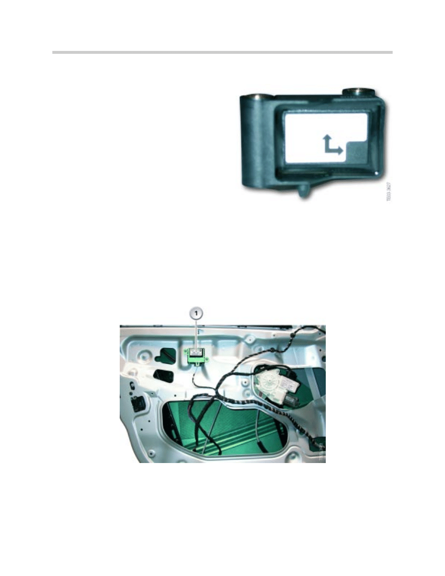
B-Pillar Satellite (MRS 4RD Only)
The MRS 4RD system does not use the con-
ventional MRSA side airbag sensors as used
on the previous MRS systems. The satellites
are mounted near the b-pillar area rather than
under the front seats.
The satellites contain lateral as well as longitu-
dinal acceleration sensors. These sensors are
capable of detecting impacts from the side as
well as front and rear.
The left are right side sensors are the same,
the only difference is in the installation. When
installed one sensor is directed at the front and
right side, the other is directed at the left and
rear.
Door Pressure Sensors (MRS 4RD only)
In addition to the b-pillar sensors, door pressure sensors have been added. This
concept, first introduced on the E65, is used to measure the pressure inside the door
cavity. In a side impact, the door skin is forced inward in turn reducing the volume. This
decrease in volume results in a sudden pressure increase.
This pressure increase is measured by the door pressure sensor and converted to an
electrical signal. This signal is passed to the MRS 4RD control module. The control
module processes this information along with the corresponding data from the b-pillar
satellite. The MRS module activates the appropriate restraint components based on this
information.
23
Multiple Restraint Systems (MRS I - MRS 4RD)
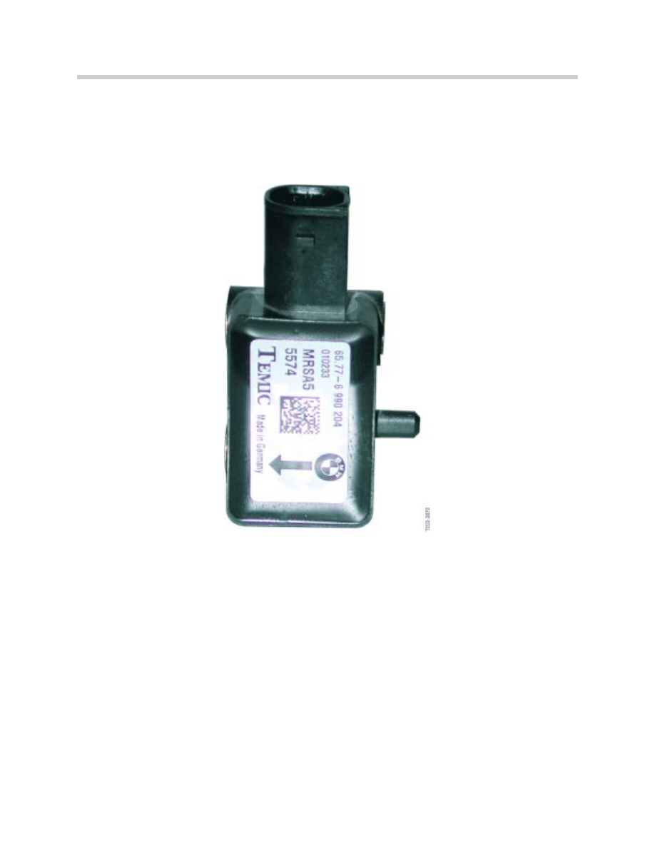
Up-Front Sensors (MRS 4RD Only)
The new up-front sensors are used on the MRS 4RD system. The first use of the up-
front sensor was on the E60, later the E83 adopted the new sensor technology. The
sensors are located on the cooling module assembly above the longitudinal subframe
members.
They are used for early detection of frontal impacts. The sensor contains a longitudinal
acceleration sensor, a signal converter and a microprocessor for data transmission.
The up-front sensors are supplied with power via a current-signal interface. The sensors
are supplied with a current of 5-10mA. When a data message is transmitted, the level
increases by approximately 20mA
The advantage of the current signal interface is its constant supply of current which pre-
vents the corruption of the signal. A change of resistance in the circuit does not affect
the signal.
Note: After an impact in which the airbags have been deployed, the up-front
sensors must be replaced. The sensors could be damaged internally,
even though no external damage is apparent. Always comply with repair
manual instructions when replacing the up-front sensors.
24
Multiple Restraint Systems (MRS I - MRS 4RD)
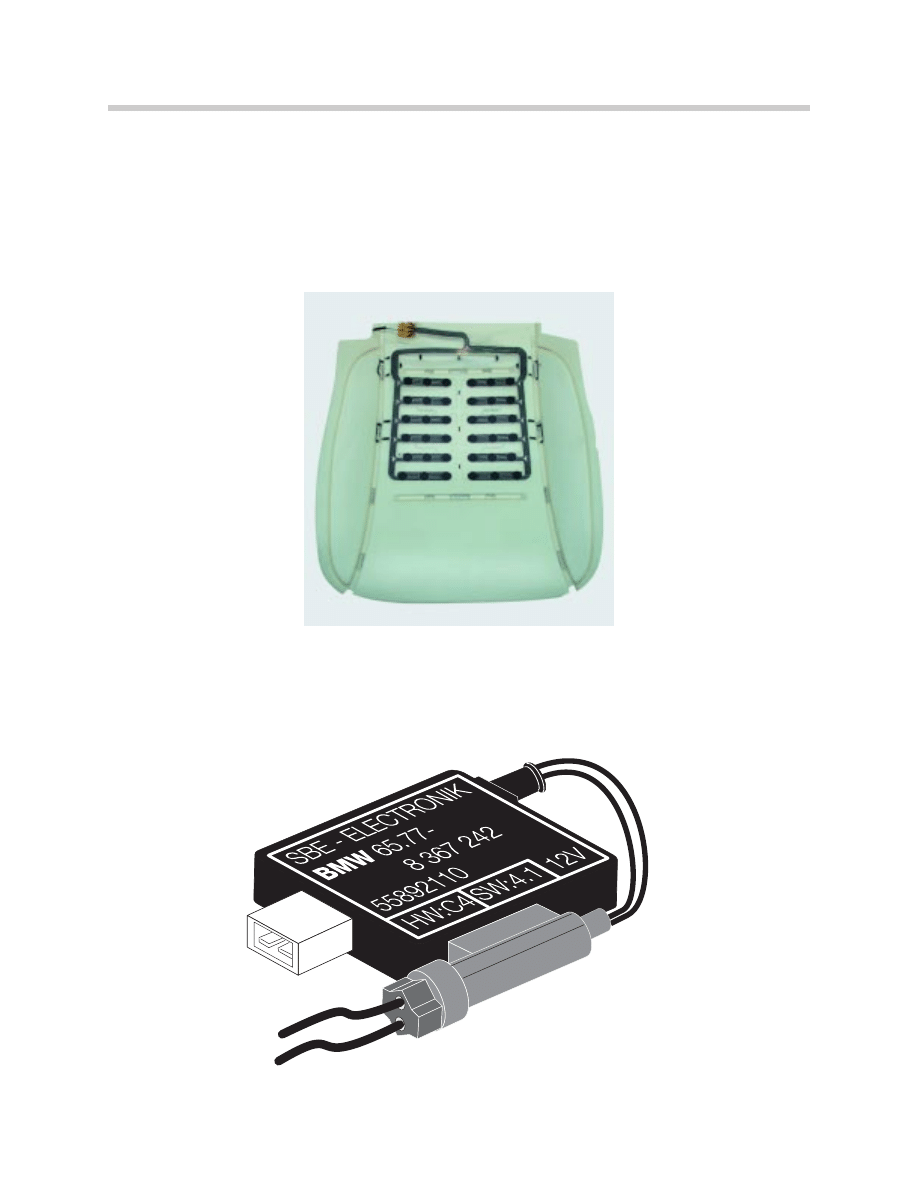
Seat Occupancy Detection (all except E83)
The Seat Occupancy Detection System (SBE), as introduced on ZAE, is continued with
MRS systems. The SBE system monitors the front passenger seat for occupants. This
information is used by the MRS module to determine airbag activation thresholds.
The SBE system consists of a pressure sensitive resistance mat which is incorporated
into the passenger seat cushion.
The SBE module is located under the passenger seat. The analog signal from the SBE
mat is converted by the SBE module to a digital signal. This signal is sent to the MRS
module via a dedicated signal line. The signal is an “occupied” or ‘unoccupied” message
to MRS.
25
Multiple Restraint Systems (MRS I - MRS 4RD)
The SBE module sends an digital signal to the MRS module. This signal is dependent
upon the status of the front passenger seat (occupied or unoccupied). There is also a 2
minute time delay when the seat becomes unoccupied. This ensures that the airbag will
be deployed in the event of a passenger briefly moving off of the seat.
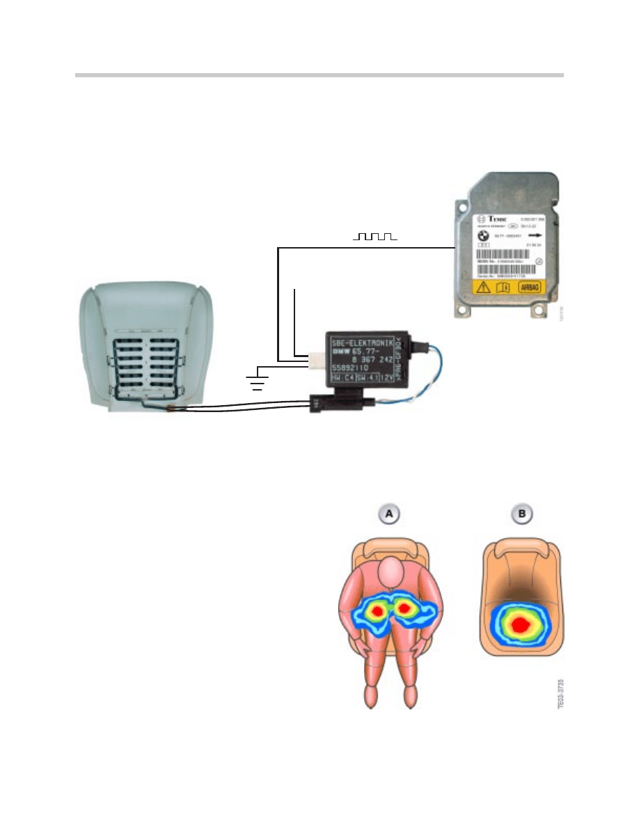
Seat Occupant Detection OC-3 (E83)
The need to differentiate between the size
and weight of the front passenger has brought
about the development of the new seat occu-
pancy detection system. The new system
designated “OC-3” (Occupant Classification
3) is capable of determining the approximate
size and weight of the passenger.
This is accomplished by using a force sensi-
tive resistance mat similar to the previous mat
already in use. The OC-3 mat however, uses
4 “resistance zones” which will monitor the
concentration and distribution of weight.
The distance between the concentration of
weight indicate whether the occupant is small
or large. An algorithm computes the weight
class and decides whether the seat is occu-
pied by a person or by a child seat.
26
Multiple Restraint Systems (MRS I - MRS 4RD)
MRS Module
SBE Module
Sensor Mat
Seat Occupancy
Signal
KLR
27
Multiple Restraint Systems (MRS I - MRS 4RD)
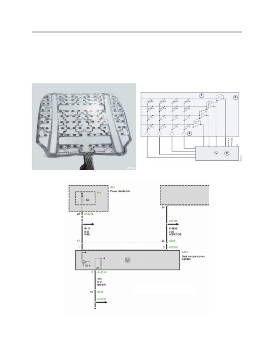
The OC-3 mat is connected to an electronic analyzer which is capable of analyzing the
information from the resistance mat.
The electronic analyzer is supplied with ground (KL31) and power from KLR. A data line
is used to send digital information to the MRS module. On the E83, the electronic
analyzer communicates with the MRS control module via the K-Bus
OC-3 Seat Occupancy
Recognition schematic

Workshop Exercise - MRS Inputs
Using an instructor designated vehicle, locate the MRS module and connect
appropriate breakout box and test cable. Observe proper safety procedures when
disconnecting airbag module.
Attention: Be sure to disconnect battery before checking airbag igniter cir-
cuits. When servicing vehicles up to 9/93 production, disconnect the battery
and wait at least 30 minutes before beginning any service procedure.
On vehicles from 9/93, wait 60 seconds before beginning any service work.
List the correct part number of the B.O.B. & harness:
Using the correct ETM, locate and list the power and ground connections below:
MRS Module connector #
KL15/R: Pin#
Ground (KL31) Pin #
List all of the input signals (including pin #) to the MRS module:
Which pin is used for the “crash output” signal?
What systems are affected by the crash output signal?
28
Multiple Restraint Systems (MRS I - MRS 4RD)

Workshop Exercise - Seat Occupancy Detection
Locate the output signal wire at the SBE module (or electronic analyzer) and connect
appropriate test cables. Using the oscilloscope, measure the seat occupancy recog-
nition signal.
Describe the SBE signal observed and record scope settings: (voltage/ time etc.)
Sit in the passenger seat and describe any changes to the SBE signal:
Vacate the seat and note the amount of time it takes for the SBE signal to change:
Using the appropriate fused jumper wire, ground the SBE signal. Describe what occurs:
(i.e. fault code/status requests etc.)
What are the thresholds for the OC-3 sensor are far as weight is concerned?
29
Multiple Restraint Systems (MRS I - MRS 4RD)

30
Multiple Restraint Systems (MRS I - MRS 4RD)
Classroom Exercise - Review Questions
1. On an MRS system, how many impacts can be recorded before the MRS module
must be replaced?
2. Which MRS system uses door pressure sensors?
A.
MRS 1
B.
MRS II
C.
MRS III
D.
MRS 4RD
3. What is the safing sensor used for and where is it located?
4. Which versions of MRS systems are connected to the K-Bus?
5. What is the difference between the side airbag sensors (MRSA) and the b-pillar
satellites used on the MRS 4RD system?
6. What is the difference between the sensor mat used on the early SBE system and
the OC-3 sensor mat?
7. The MRS module contains 2 sets of capacitors. What are the purposes of these
capacitors?
8. What type of signal is sent by the up-front sensors when an impact is detected?
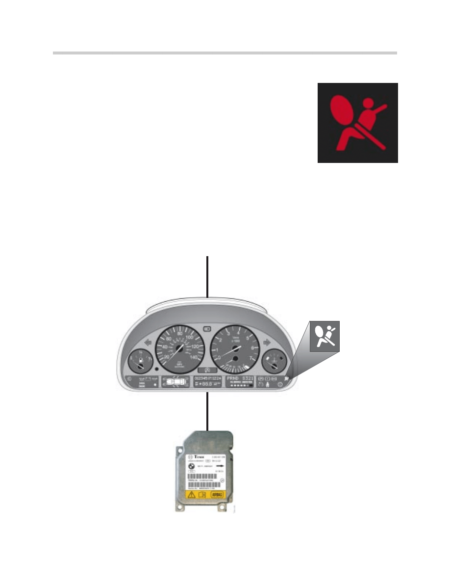
Airbag Warning Lamp (AWL)
On MRS systems, the AWL is used to warn the driver of faults
within the airbag system. Each time terminal R (KLR) is switched
on, a self test is performed of the internal circuits of the MRS mod-
ule. Also, the peripheral components (airbags/sensors etc.) are
checked as well.
Once this self test is complete (3-4 seconds), the airbag warning
lamp goes out. Once the AWL is off, the system is ready to deploy
the airbags when needed.
The system is continuously monitored from the time KLR is switched on. If a fault occurs
within the system, the AWL is illuminated and a relevant fault is stored. The AWL will stay
illuminated (with KLR) until the fault is rectified and fault memory is erased.
The AWL circuit is supplied with with power from KLR/KL15 and the MRS control unit
controls the ground side of the circuit to activate the LED in the cluster.
31
Multiple Restraint Systems (MRS I - MRS 4RD)
MRS Module
KL 15
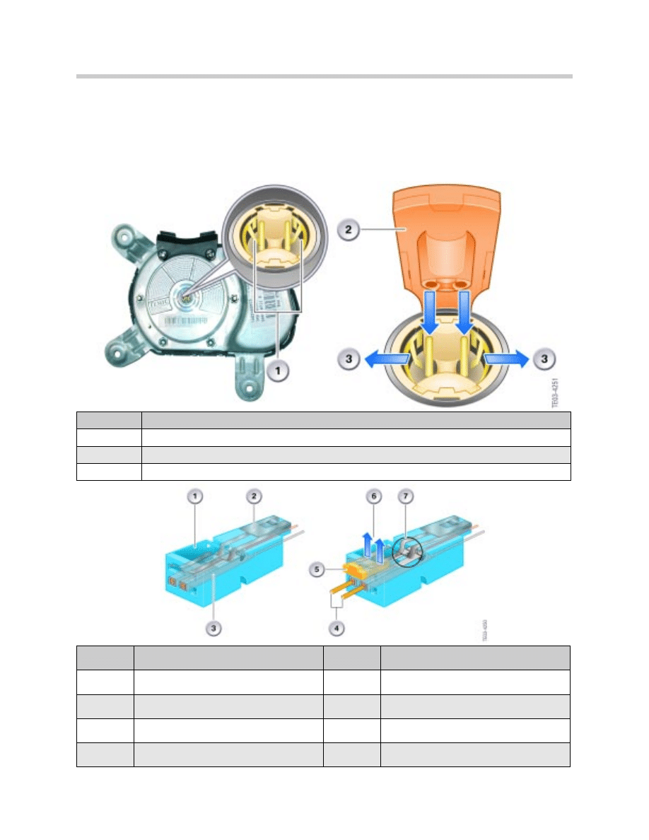
Airbag Wiring and Connectors
All pyrotechnic components are fitted with a shorting bridge on all plug connectors. This
prevents pyrotechnic devices from being accidentally discharged during service work.
The shorting bridges create a short circuit across the pins which eliminate the possibility
of a voltage potential between the two pins.
32
Multiple Restraint Systems (MRS I - MRS 4RD)
Index
Explanation
1
Shorting bridge shown in short circuit position
2
Connector
3
Shorting bridge (pushed apart by connector)
Index
Explanation
Index
Explanation
1
Connector Plug
5
Plastic pin on connector
2
Shorting bridge resting on female contacts
6
Shorting bride shown (raised by connector)
3
Female contacts
7
Shorting bridge shown (disconnected)
4
Male connector pins
During service, when the diagnostic test plan requires a resistance measurement, it is
very important to use the correct test cable. This ensures that the shorting bridges are
opened. Failure to do so would result in incorrect resistance measurements.
Test cables can be found in special tools (SWZ) in group 61 and 62.
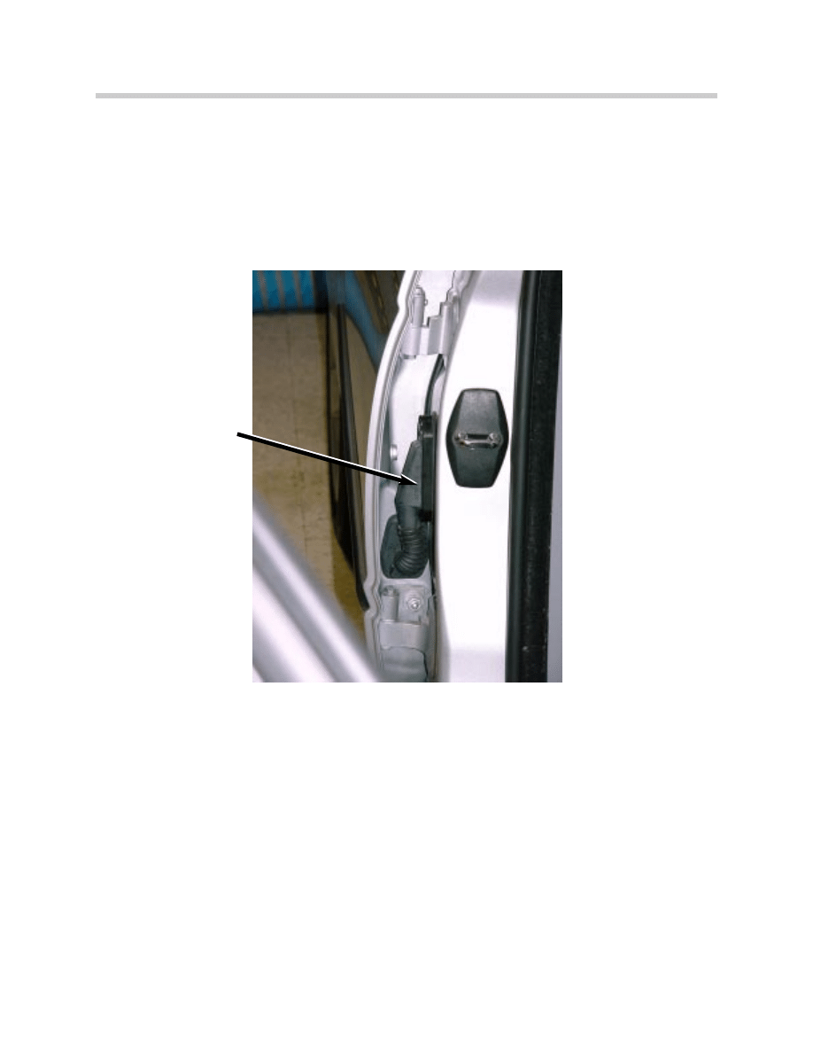
Be aware that the wiring for the side airbag(s) goes through the A-pillar (b-pillar rear) for
the firing circuit. This area is susceptible to intermittent connection concerns due to the
movement from opening and closing of the door.
Note: When diagnosing a side airbag igniter circuit, always take into account
the condition of the wiring, terminals and connector. These items should
be checked first before replacing any components (i.e. Airbag or MRS
Module).
The best way to diagnose this circuit is to perform a wire test (preferred) or a resistance
check. The A-pillar connector should be manipulated (wiggled) to check for intermittent
open connections.
Repair kits are available for the door wiring harness and vehicle harness.
Always check the available Service Information such as Service bulletins and measures
as well as the latest repair instructions.
33
Multiple Restraint Systems (MRS I - MRS 4RD)
B-Pillar Connector E46
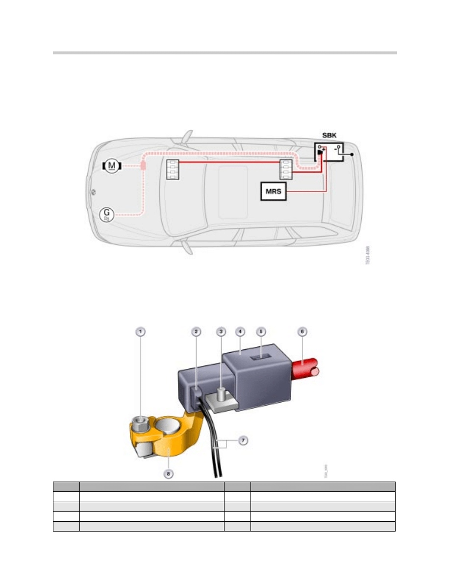
Battery Safety Terminal
The Battery Safety Terminal (BST) was added to the vehicle electrical system with MRS II
systems. Since the battery is located in the rear of the vehicle, there is a considerable
amount of unprotected (unfused) cable running from front to rear. The BST is used to
protect from short circuit to the B+ cable in the event of a severe impact.
Upon impact the BST will disconnect the B+ cable to the starter and alternator. However
the power will remain connected to the power distribution circuits. These circuits are
fused and not in danger of an unprotected short circuit. These circuits will remain active
after an impact to allow operation of other systems such as power locks, windows and
hazard lighting.
34
Multiple Restraint Systems (MRS I - MRS 4RD)
Index
Explanation
Index
Explanation
1
BST B+ Terminal attaching screw (M6)
5
BST Retaining Spring Clip
2
BST Igniter Pellet
6
BST B+ Cable to Starter/Alternator
3
B+ connection to vehicle power distribution
7
BST Igniter Pellet Connection/ 2-wire
4
BST Plastic Housing
8
BST Positive Battery Terminal
The BST consists of a conventional battery
cable terminal which is modified to contains a
hollow discharge tube.
One end of the discharge tube contains a
small igniter pellet made from a solid propel-
lant. attached to the B+ battery terminal.
The battery cable end has a tapered (conical)
connection which is pressed into the battery
terminal at the opposite end of the discharge
tube.
The BST housing is enclosed in a plastic
housing which protects it from damage. The
plastic housing contains two plastic spring
tabs.
The spring tabs will catch and retain the bat-
tery cable connection after deployment. This
ensures no accidental contact between the
battery cable and the B+ terminal.
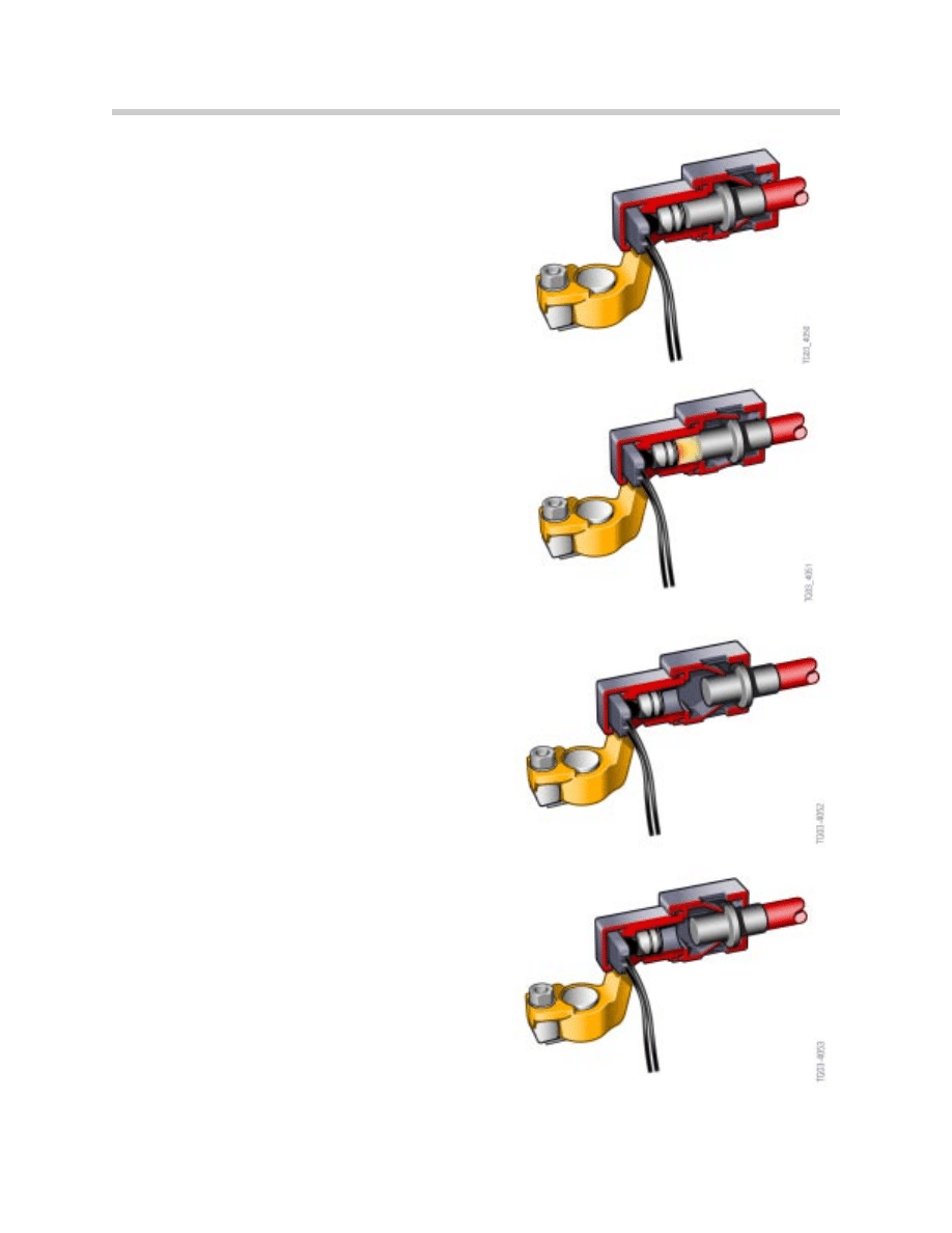
Upon deployment, the igniter pellet is trig-
gered by the MRS control module. The
resulting gas that is discharged forces the
tapered end of the B+ cable to separate from
the battery terminal.
Once the battery cable is separated, the plas-
tic spring tabs will retain the cable.
Once the separation is complete, the starter,
alternator and battery cable are now isolated
from battery power.
The remainder of the vehicle electrical system
is still powered. The power distribution cen-
ters are still connected to the battery terminal
via a cable.
During a frontal impact the BST is deployed
with the front airbags. In a rear impact the
BST is deployed at the same time as the seat
belt tensioners. If a side impact is detected,
the BST is trigger along with the side and
head airbags.
35
Multiple Restraint Systems (MRS I - MRS 4RD)
BST Not Deployed
BST Igniter Triggered
BST Separation
Process Complete
Spring Tabs
Retaining B+ Cable
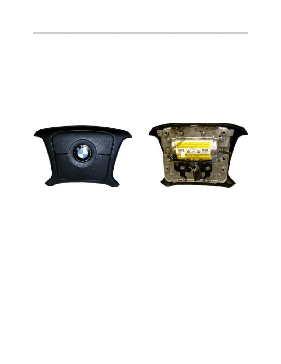
Drivers Airbag
The driver airbag,which is mounted on the steering wheel, consists of a tightly folded
inflatable cushion constructed of nylon and plastic.
The early airbag systems used a single stage airbag which was deployed by using an
ignition squib to ignite a small amount of propellant. This propellant expands, filling the
airbag assembly. The airbag deploys by tearing the airbag cover at pre-determined “frac-
ture lines”. The ignited propellant exits the rear of the airbag assembly after being
cleaned and cooled through a metal filter in the airbag housing.
The current airbag systems, which have been in use since the 1998 model year, use a 2-
stage (Smart) airbag which uses the “cold gas” inflation method. The 2-Stage driver’s
side airbag was introduced in March of 1999.
The 2-stage airbag assembly consists of an accumulator/gas generator assembly with 2
ignition capsules. Upon deployment, an inert gas mixture is used to inflate the airbag to a
capacity of approximately 64 liters.
The use of two ignition stages, coupled with the lower volume and new propellant, opti-
mizes the deployment of the airbag and makes it less aggressive when the airbag inflates.
Note: Airbags do not replace conventional safety restraints (seatbelts). When
handling an airbag, always place the airbag with the emblem side up.
36
Multiple Restraint Systems (MRS I - MRS 4RD)
2-Stage airbag front view
2-Stage airbag rear view
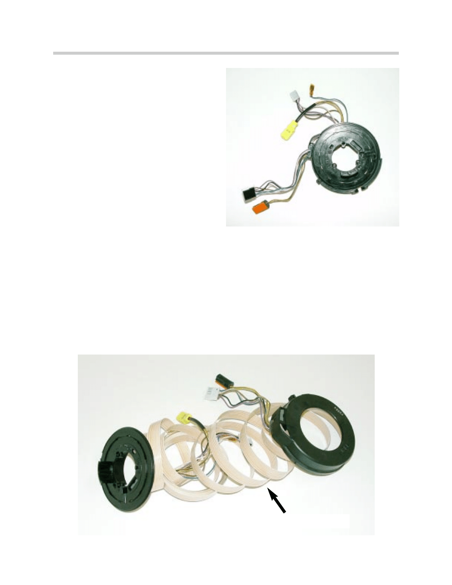
Airbag Contact Ring
In order to maintain contact between the
driver’s side airbag and the MRS control
unit when the steering wheel is turned, a
special device was developed. This
device is referred to as the contact ring.
The contact ring consists of a loosely
wound coil of flat ribbon cable.
This arrangement allows the steering
wheel to turn approximately 3-4 turns from
lock to lock and still maintain the airbag
ignition circuit connection. The horn cir-
cuit and MFL signals are also routed
through separate circuits in the ribbon
cable.
Note: When servicing the vehicle it is important not to turn the contact ring
beyond its maximum number of turns, this can result in a broken ribbon
cable. For instance, any work involving the steering column.
Extra care should be taken to ensure the steering wheel is not turned
with the steering rack disconnected. This situation would allow the
steering wheel to be turned beyond the capability of the contact ring.
Removing the key completely from the ignition is the best way to prevent
the steering wheel from being turned inadvertently. Always follow the
appropriate repair instructions as they pertain to the contact ring assembly.
37
Multiple Restraint Systems (MRS I - MRS 4RD)
Contact ring disassembled
(for demonstration only, DO NOT
attempt disassembly. Contact ring
will be rendered unusable).
Ribbon cable in contact ring
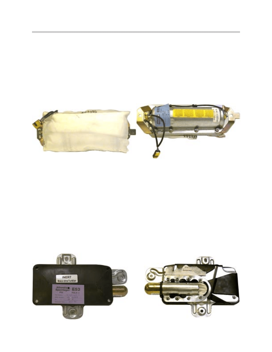
Passenger Airbag
Passenger airbags have been standard equipment on BMW vehicles since 1993. Just as
with the driver airbag, the passenger side airbag uses an inflatable plastic cushion. One
difference is that the passenger airbag has a larger inflated volume (105 liters).
Early passenger side airbags also used single stage inflation until 9/98. The “Cold Gas”
inflation technique was also used on the 2-stage SMART passenger airbag. The
SMART passenger side airbag was installed on MRS II equipped vehicles from 9/98.
When the front passenger airbag inflates, a flap connected to the dash panel is opened.
The flap is retained by a strap, then the airbag opens toward the windshield. When fully
deployed, the airbag rests on the windshield and dashboard panel.
Side Airbag
The side airbag is also referred to as the thorax airbag. This is due to the fact the this
airbag is designed to protect the thorax (chest/torso) region of the occupant.
The side airbags are mounted on the inner door frame on the front and (optional) rear
doors. Deployment of the side airbags is dependent upon the triggering thresholds pro-
grammed in the MRS module. These thresholds are determined from inputs from the
satellites and internal crash sensors.
38
Multiple Restraint Systems (MRS I - MRS 4RD)
2-Stage Passenger Airbag (Front View)
2-Stage Passenger Airbag (Rear View)
Head Protection Systems
The BMW Head Protection System (HPS) was first used on MRS II systems. It was
installed on the E38 in May of 1997 and then added to the E39 in September. HPS was
also added to the E46 (Sedan/Coupe) and the E53 as well.
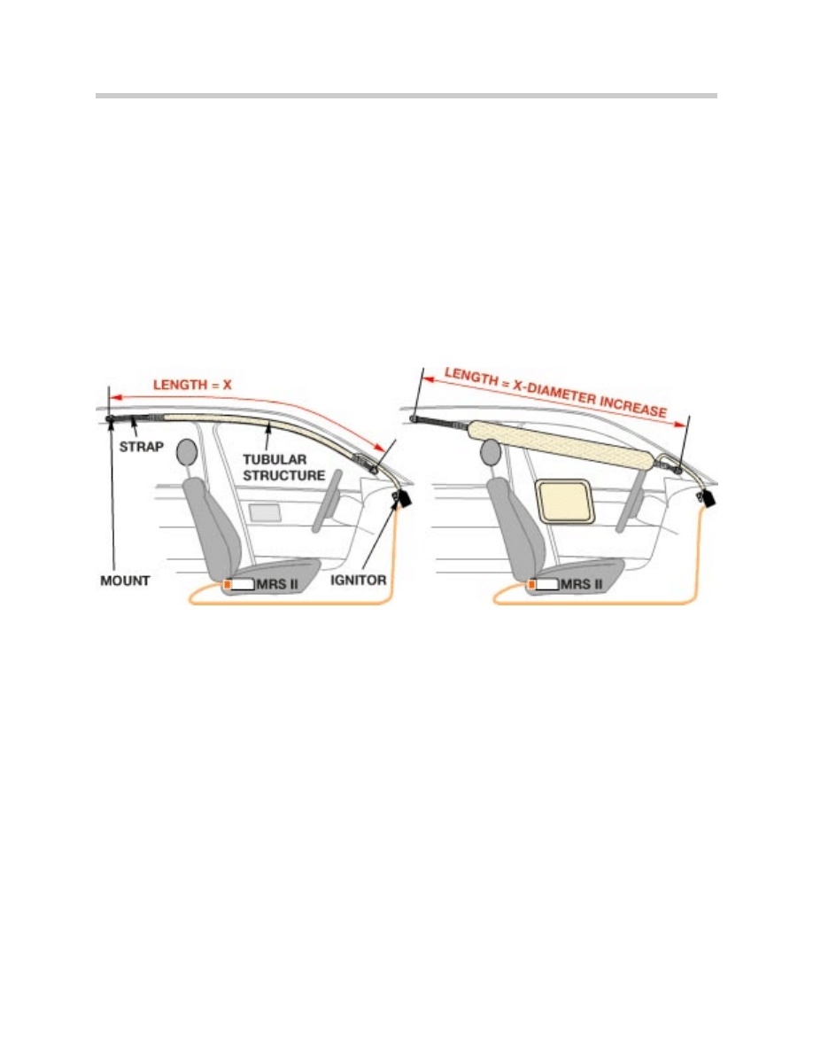
The HPS system consists of the Inflatable Tubular Structure (ITS). The ITS is designed
to protect the head and neck of the occupant in side impacts. Head injuries account for a
large portion of overall accident injuries. So, the ITS is a natural enhancement of BMW
Passive Safety Systems.
The ITS is constructed of an outer woven tube with an inner tube of polyurethane. The
woven structure is secured by straps at either end. The straps are secured in the vehicle
at the A-pillar and beside the grab handle in front of the C-pillar. The volume of the ITS
airbag is approximately 11 liters.
The tubular portion of the ITS is always the same size regardless of application. By alter-
ing the length of the retaining straps, it is easy to adapt the ITS assembly in different
BMW models.
Upon sufficient side impact, the gas generator in the ITS will be ignited by the MRS mod-
ule. After ignition, the gas flows through a flexible tube and inflates the ITS. The woven
structure will expand causing the overall length of the ITS assembly to decrease. This
causes the ITS to exit from the roof and pillar trim.
The ITS will unfold in a diagonal pattern to protect the occupant. The diagonal arrange-
ment is designed to protect occupants of different sizes.
39
Multiple Restraint Systems (MRS I - MRS 4RD)
After impact, the ITS is not vented for deflation, it will gradually deflate as the gas cools
over a period of time. This process occurs slower than the airbags to protect the occu-
pant from secondary impacts or rollover situations.
The head protection airbags are always activated together with the side airbags on an
MRS II system. On MRS III systems and later, the passenger side (thorax) bag is not
deployed if the passenger seat is not detected as occupied.
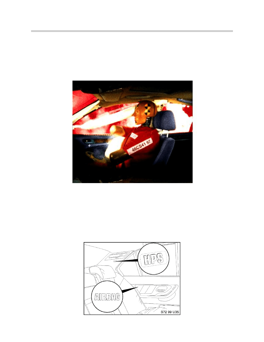
Rear HPS
In addition to front Head Protection, rear HPS optional with the rear side airbag option.
Rear HPS is available on E38, E39 and E53.
The rear HPS airbag is a cushion (not an ITS) that is deployed from behind the C-pillar
trim. The HPS will not be de-activated along with the side airbags from the factory since
there is no danger to small children sitting out of position.
A vehicle with rear HPS can be identified by observing the “HPS” tag embossed in the
C-pillar cover.
40
Multiple Restraint Systems (MRS I - MRS 4RD)
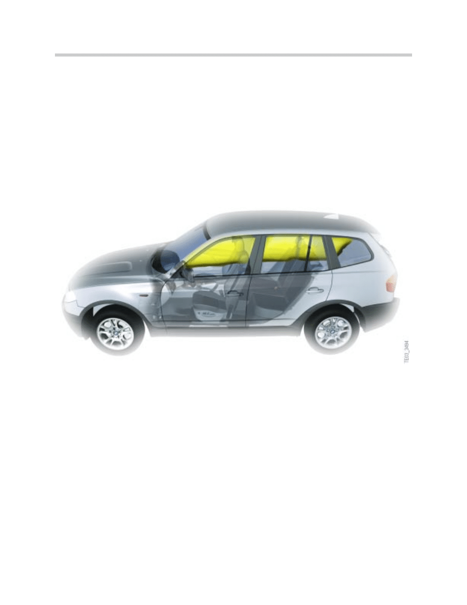
Head Airbag (Curtain Airbag)
On the E83, a new head protection system , the curtain airbag is introduced as standard
equipment for the first time. It differs from the head protection (ITS) previously used. The
airbag is now a continuous curtain airbag from the A to C-pillar.
The system covers the entire side window area between the occupants and the vehicle
windows and pillar areas. In conjunction with the side airbags in the front and the rear
doors, it provides optimum protection for all passengers in the event of a side impact.
The advantages of the system are as follows:
• Extended coverage area for the side windows - front and rear
• Protection against glass splinters and penetrating objects
• Optimized protective area offering protection for occupants of different sizes
41
Multiple Restraint Systems (MRS I - MRS 4RD)
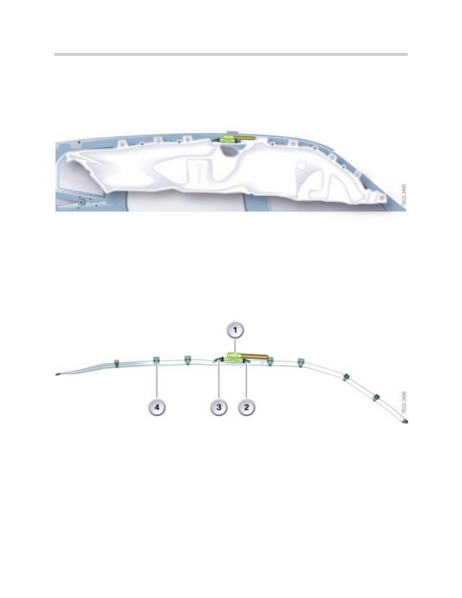
The curtain is positioned along the line of the roof side member, folded up. It consists of
a gas generator, two gas nozzles and the curtain.
In the event of a side collision, the generator is detonated and the gas flows through the
two gas nozzles into the curtain. Simultaneous inflation of the curtain and the front and
rear achieves more even deployment.
The attachment of the curtain airbag to the A-pillar and C-pillar pulls it into position.
Being a sealed system, the curtain airbag retains its shape and strength for several
seconds.
42
Multiple Restraint Systems (MRS I - MRS 4RD)
1. Gas Generator
2. Front Gas Nozzle
3. Rear Gas Nozzle
4. Airbag Retaining Clips
Seatbelt Tensioning Systems
It has already been proven that 3-point seatbelts offer an unsurpassed level of protection
during a motor vehicle accident. However, BMW has added some improvements to
increase the level of safety as well as the comfort level of the occupant.
In order to make the seat belt comfortable to wear while driving, the belt must have a suf-
ficient amount of travel to allow movement but the slack must be kept to a minimum.
This inertia reel is designed to keep a sufficient amount of tension but to lock under cer-
tain conditions.
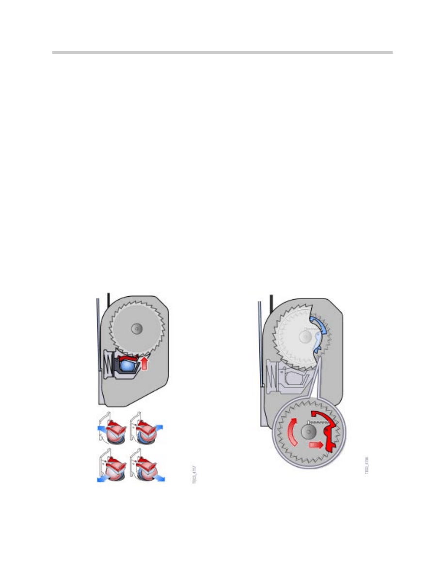
The inertia reel has two independent locking systems that will lock under various driving
conditions. The two locking systems are:
• Ball Type Mechanism - The ball type mechanism uses a ball bearing and lever
mechanism which responds to changes in g-force. During extreme cornering, high
bank turns, sharp braking and in a collision, the seat belt will be locked in place by
the toothed wheel in the inertia reel, the toothed wheel is blocked by the ball and
lever assembly.
• Centrifugal Mechanism - The centrifugal mechanism will lock the seatbelt when it is
pulled quickly from the reel. This can be demonstrated by jerking the seat belt out
of the reel quickly, the seat belt should lock immediately and then unlock once the
belt is released and pulled out slowly.
43
Multiple Restraint Systems (MRS I - MRS 4RD)
Ball Mechanism
Centrifugal Mechanism
Pyrotechnic Seatbelt Tensioners
The inertia reel mechanism is designed to
minimize the amount of belt slack, however
this does not take into account the elasticity of
the seat belt. Also, the seating position and
the thickness of the occupants clothing must
also be considered.
To counteract these possibilities, BMW has
installed a pre-tensioning mechanism to
reduce the slack in the seat belt during an
impact.
Once an impact of sufficient severity is detect-
ed, the gas generator in the pre-tensioned will
tighten the seat belt approximately 55mm.
This will prevent the occupant from sliding
under the seatbelt, an effect referred to as
“submarining”.
This ensures that during an impact, the upper
body will shift forward which improves the
effectiveness of the airbag.
There are 4 types of seat belt pre-tensioning
devices used in BMW vehicles. On MRS
equipped vehicles, the pre-tensioners in use
are the pyrotechnic type.
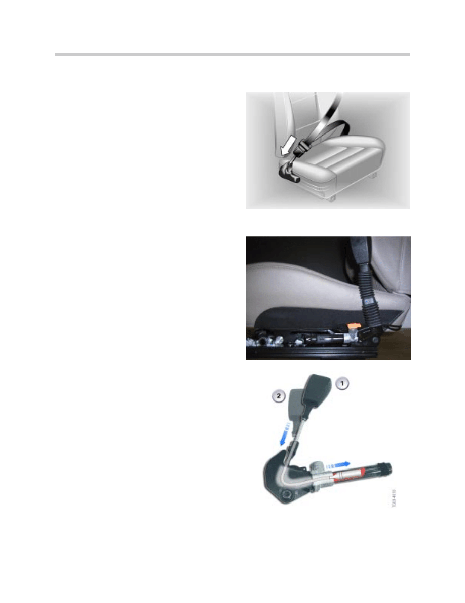
The pyrotechnic seat belt tensioned consists
of a seat belt buckle attached to a steel cable.
The steel cable is fitted to a piston at the end
of the cable. The piston is installed in a steel
tube which contains a small amount of solid
propellant.
Upon impact, the propellant is ignited and the
piston is driven down the tube. This in turn
pulls the steel cable which pulls the seat belt
buckle downward.
After an accident where the pre-tensioners are
deployed, they must be replaced.
44
Multiple Restraint Systems (MRS I - MRS 4RD)
1. Before Accident
2. After Accident
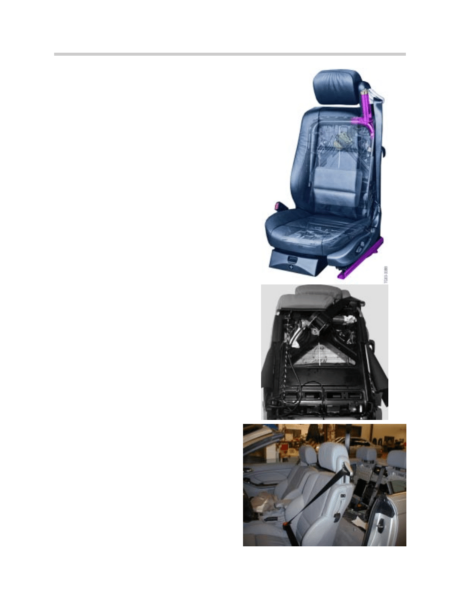
Seat Integrated Belt Systems (SGS)
The SGS system is used on vehicles that do
not have a b-pillar post. The first vehicle to
use the SGS seat was the E31. Currently, the
E46 convertible and the E64 use the SGS
seat.
All seat belt attaching points including the
upper anchor point are integral to the seat
frame. All of the forces in a collision are
absorbed by the seat frame and the floorpan.
The SGS seat allows the best possible seat
belt geometry in relation to the occupant.
The seat belt is wrapped tightly around the
occupant irrespective of seat position and
body size. This helps reduce the amount of
free seat belt length and also further reduces
excessive slack.
The features of the SGS seat are as follows:
• All of the seat belt attachment points are
connected to the seat frame.
• The inertia reel clamps the seat belt at
the closest possible point to the occu-
pant.
• Optimum protection of occupants in the
event of a collision.
• Seat belt strap is released when the
backrest is folded or adjusted.
• Comfort is maximized by allowing ideal
body restraint for any seat setting or body
size.
• Restricted forward displacement of occu-
pant due to additional seat belt strap ten-
sioner.
• More protection during rear and side
impact.
• No “submarining” effect.
• Ideal solution for vehicles without b-pillar
45
Multiple Restraint Systems (MRS I - MRS 4RD)
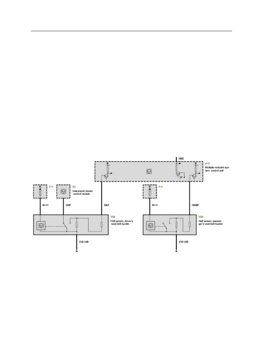
Seat Belt Contacts
Regardless of seat type or tensioning device used, all seat belt buckles have a switch
mechanism. The seat belt buckle switch has a dual purpose. The switch reports seat
belt status to the MRS module for the purpose of trigger logic. The MRS can then actu-
ate the necessary pyrotechnic devices (e.g. belt tensioner, airbags etc.)
The seat belt is also used for the seat belt warning light. This feature will illuminate the
seat belt warning light if the vehicle is started without the seat belt being fastened.
Early seat belt mechanisms used a mechanical type switch. Later models adopted a
hall-effect switch to increase reliability.
The hall-sensor buckle switch has been in use on most models since March of 1997.
46
Multiple Restraint Systems (MRS I - MRS 4RD)

Workshop Exercise - Checking Airbag Igniter Circuits
Using an instructor designated vehicle, check the following airbag circuits:
Attention: Be sure to disconnect battery before checking airbag igniter cir-
cuits. When servicing vehicles up to 9/93 production, disconnect
the battery and wait at least 30 minutes before beginning any ser-
vice procedure. On vehicles from 9/93, wait 60 seconds before
beginning any service work.
From the MRS module connector, check the resistance of the side airbag circuits.
What is the observed resistance?
Using the “resistance tool” supplied by the instructor, apply an increasing amount of
resistance until the AWL is illuminated.
What is the minimum resistance required to illuminate the AWL?
With the increased resistance in place, perform the applicable test module as per
DISplus/GT-1 instructions.
What does the test module conclude as the root cause?
What does the test module state as the correct resistance range for the side airbag
circuit?
From the MRS module connector, check the resistance of the driver’s side airbag
(both stages):
What is the resistance observed?
47
Multiple Restraint Systems (MRS I - MRS 4RD)
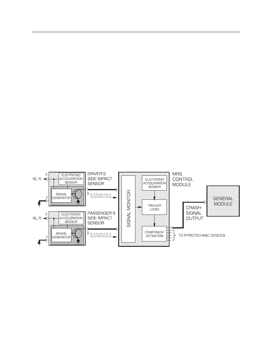
Principle of Operation
Crash Output Signal
The Crash Output Signal (CA) is an output of the MRS control module. In the event of an
impact, various systems will by activated to facilitate access by rescue personnel. The
door locks (if locked) will be unlocked, the interior lights will be turned on and the hazard
warning flashers will be activated.
To accomplish this, the MRS module sends a “crash output” signal (CA) to various sys-
tems within the vehicle. Depending on the vehicle model and system fitted, the crash
signal will be a 12 volt high/low signal or a bus telegram over the K-Bus.
The body electronic system (ZKE III, IV or V) receive the crash signal for the activation of
the locks and interior lights. The lighting system (LCM or LSZ) also receives the crash
signal for activation of the hazard lights.
48
Multiple Restraint Systems (MRS I - MRS 4RD)
Crash signal on vehicles without K-Bus
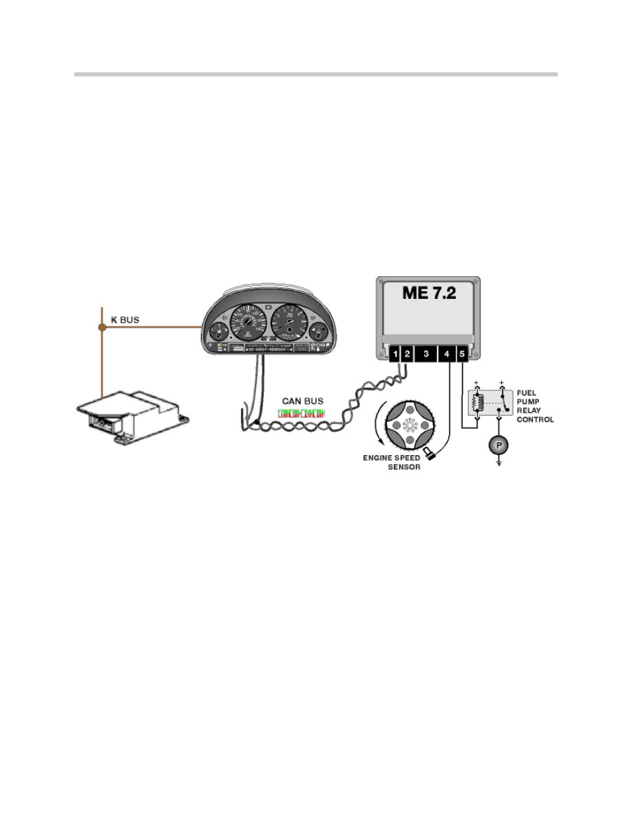
Fuel Pump Cutoff Circuit
Beginning with MRS III, the fuel pump operation will be de-activated during an impact for
added safety. The MRS module sends a “crash message” over the K-bus. This K-bus
message is processed by the cluster and sent to the ECM via the CAN bus.
The ECM interrupts fuel pump operation by de-activating the control circuit of the fuel
pump relay.
49
Multiple Restraint Systems (MRS I - MRS 4RD)
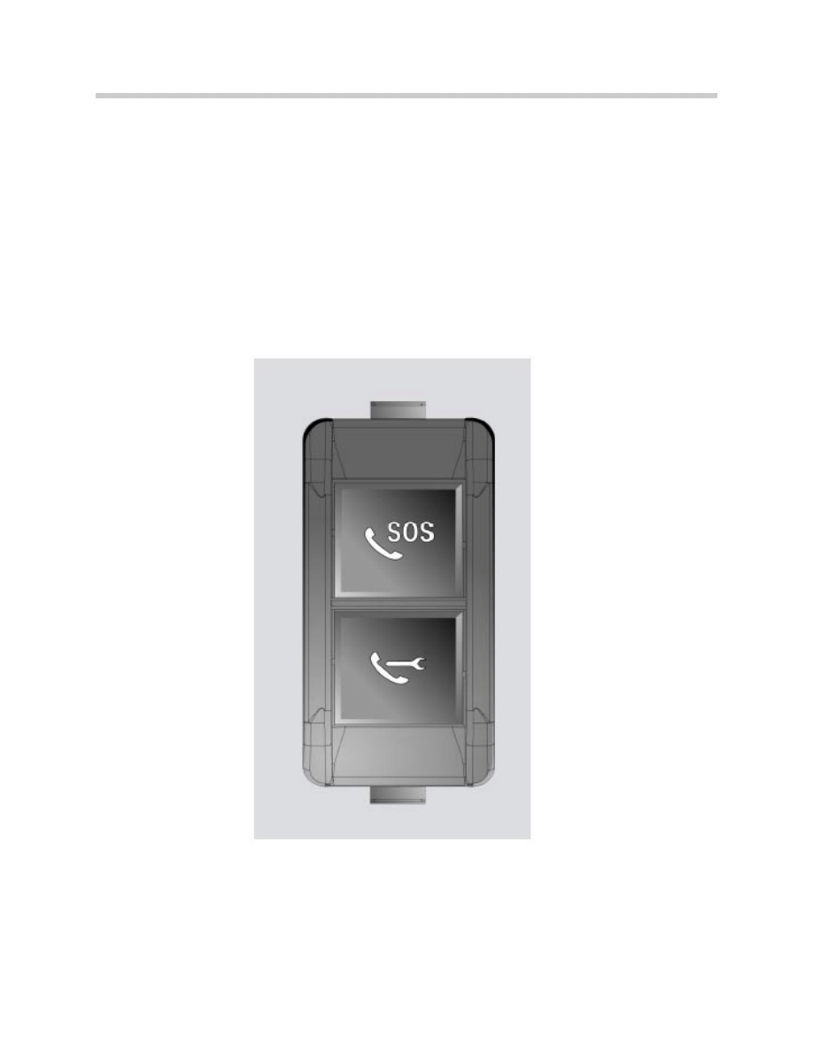
SOS/Emergency Call
Beginning with the 2004 3 series and the X3, the SOS/emergency call feature can now
be initiated by the MRS control module via the K-bus. Upon airbag deployment, the
MRS control module will send a K-bus telegram to the Telematics Control Unit (TCU) to
send an emergency call.
The new TCU is equipped with GPS capability that allows the vehicle to be located by
emergency personnel.
50
Multiple Restraint Systems (MRS I - MRS 4RD)

Workshop Hints
Checking Airbag Resistance
When checking airbag resistance, always use the correct test cable. This ensures that
the shorting bridges are disconnected. Failure to do so will result in improper resistance
readings during testing.
Repairing Airbag Wiring
As a general rule, airbag wiring is not to be repaired unless specified in a service bulletin
or outlined in repair instructions. There are some repair kits available in the parts system.
These are usually for side airbag ignition circuits.
Airbag De-activation
De-activation of Airbags (front and front side)
On certain vehicles, it is possible to de-activate the front passenger and front side
airbags and the rear side airbags upon customer request.
As far as the de-activation of the front passenger airbag is concerned, refer to BMW
Service Information Bulletin (SIB) B 72 08 97. All of the necessary regulations and
procedures are outlined here.
To deactivate the passenger side airbags (and rear side airbag), a special code will need
to be obtained from BMW NA. The “special code” is used in ZCS/FA coding to properly
de-activate the specified airbags.
The bulletin also outlines the proper forms to be used. The customer will have to fill out a
necessary disclaimer/authorization form for this.
The forms are then faxed to BMW NA via the BMW center. The necessary fax numbers
are also outlined in the SIB.
De-activation of Airbags (rear side)
On some vehicles, the customer may request to have the rear side airbags de-activated
as well as the rear HPS (not recommended).
In response to this some vehicles produced from 6/99 (E38, E39 and E65) come from
the factory with the rear side airbags de-activated and disconnected.
Therefore in order for the side airbags to be active, the customer must fill out the neces-
sary forms and have the rear airbags re-connected and re-activated via coding.
Refer to BMW SIB B 72 03 99, which contains all of the necessary procedure.
51
Multiple Restraint Systems (MRS I - MRS 4RD)

Classroom Exercise - Review Questions
1. What are the two purposes of the seat belt contacts?
2. What is the purpose of the shorting bridges in the airbag igniter circuits?
3. What is unique about the head protection system on the E83 (X3)?
4. What airbag system was the first to use BST?
5. Which MRS systems have the capability to cut-off the fuel pump operation in the
event of an impact?
6. What vehicles are equipped with the SGS seat and why?
7. Why is there no venting on the ITS assembly?
52
Multiple Restraint Systems (MRS I - MRS 4RD)

53
Multiple Restraint Systems (MRS I - MRS 4RD)
8. When diagnosing an igniter circuit on a side airbag, what should be considered
BEFORE replacing any airbag components (i.e. MRS module or side airbag)?
9. Which MRS systems are equipped with HPS?
10.What are the two types of locking system mechanisms used on the inertia reel?
11.What is the approximate resistance of an airbag igniter circuit?
12.What precautions should be observed when performing repairs to the airbag
contact ring or surrounding components?
Review Notes:
Document Outline
- Main Menu
- Introduction to Passive Safety
- Multiple Restraint Systems (MRS I - MRS 4RD)
- E90 Multiple Restraint Systems 5
- Byteflight Safety Systems
- Rollover Protection Systems
- Advanced Crash and Safety Management
- Glossary
Wyszukiwarka
Podobne podstrony:
10 E90 Multiple Restraint System 5
Multiplex Communication System
96ZJ 8M PASSIVE RESTRAINT SYSTEMS
93ZJ Secc 8M Restraint Systems
02a Organizacja systemu ubezpieczeń społecznychid 4030 pptx
System finansowy w Polsce 2
Systemy operacyjne
Systemy Baz Danych (cz 1 2)
Współczesne systemy polityczne X
System Warset na GPW w Warszawie
003 zmienne systemowe
elektryczna implementacja systemu binarnego
09 Architektura systemow rozproszonychid 8084 ppt
SYSTEMY EMERYTALNE
3 SYSTEMY LOGISTYCZNE
więcej podobnych podstron