1
E

Contents
1. Introduction --------------------- 1
Features of MOSS-TRI ----------------- 1
2. Bank M Program Structure -- 2
Program structure ------------------------ 2
Editing -------------------------------------- 3
Characteristics of each oscillator ---- 4
3. Parameters ---------------------- 5
Program Play Mode --------------------- 5
Program Play P1 ---------------------- 5
1–1: Program Play ------------------ 5
Program Edit Mode --------------------- 6
Program Edit P1 ---------------------- 6
1–1: Prog Basic ---------------------- 6
1–2: OSC Basic -------------------- 10
1–3: OSC 1 Pitch ------------------ 12
1–4: OSC 2 Pitch ------------------ 13
1–5: Sub Pitch --------------------- 13
Program Edit P2 -------------------- 14
2–1: OSC ---------------------------- 14
01: Standard ----------------------------------- 14
02: Comb Filter ------------------------------- 17
03: VPM ---------------------------------------- 19
04: Resonance --------------------------------- 21
05: Ring Modulation ------------------------ 23
06: Cross Modulation ----------------------- 24
07: Sync Modulation ------------------------ 25
08: Organ Model ----------------------------- 26
09: Electric Piano Model ------------------- 28
10: Brass Model ------------------------------- 30
11: Reed Model ------------------------------- 33
12: Plucked String Model ------------------ 36
13: Bowed String Model ------------------- 40
2–2: OSC 2 -------------------------- 42
2–3: Sub/Noise ------------------- 43
Program Edit P3 -------------------- 45
3–1: Mixer -------------------------- 45
3–2: Filter 1 ------------------------- 47
3–3: Filter 1 SUB ------------------ 50
3–4: Filter 2 ------------------------- 52
3–5: Filter 2SUB ------------------- 52
Program Edit P4 -------------------- 53
4–1: Amp --------------------------- 53
4-2: Amp EG ----------------------- 55
Program Edit P5 -------------------- 57
5–1: EG 1 ---------------------------- 57
5–2: EG 2 ---------------------------- 59
5–3: EG 3 ---------------------------- 59
5–4: EG 4 ---------------------------- 59
Program Edit P6 -------------------- 60
6–1: LFO 1 -------------------------- 60
6–2: LFO 2 -------------------------- 62
6–3: LFO 3 -------------------------- 62
6–4: LFO 4 -------------------------- 62
Program Edit P7 -------------------- 63
Program Edit P8 -------------------- 63
4. Data ----------------------------- 64
Retrigger Controller List ------------ 64
Modulation Source List -------------- 64
Precautions ------------------------------ 65
Additional message ------------------- 65
Contents
1. Introduction
Thank you for purchasing the MOSS-TRI DSP Synthesizer Option. To ensure long and trouble-free
enjoyment, please read this user’s guide carefully and use the product correctly.
Before you use this product, be sure to read the “Safety precautions” found at the beginning of the Parameter
Guide.
This guide explains the bank M parameters which are added when the MOSS-TRI DSP Synthesizer Option
is installed (pre-installed in the Trinity V3 series). For details on parameters other than bank M, refer to
your Parameter Guide, Basic Guide, and Effect Guide.
When this option is installed (pre-installed in the Trinity V3 series), the bank S programs created by the
Solo-TRI option
will become invalid. However, explanations of bank S in the Parameter Guide, Basic Guide,
and Effect Guide will still apply to “bank M”.
Also, please refer to the Voice Name List for V3 together with the Voice Name List which you already have.
In combination mode, bank M programs can be selected only for one timbre (☞page 4 in Parameter Guide).
In Sequencer mode, bank M programs can be selected only for one track (☞ page 72 in Parameter Guide).
If a bank M program is selected for any timbre in a combination, the D-mod Src “Tempo” for the AMS or
effect of the timbre program will use the Prog. Tempo setting (☞page 61 of this manual) (when the MIDI
Clock Source is Internal).
In all modes, you must use an insertion effect when using bank M programs. If you do not use an insertion
effect, the output will be low.
Features of MOSS-TRI
This is a MOSS (Multi-Oscillator Synthesis System) tone generator with six voices of polyphony.
Bank M
contains 64 sounds which use the MOSS tone generator. When the PBS-TRI Flash ROM
Option
is installed, an additional 64 sounds are added to bank M, bringing the total to 128 sounds.
The MOSS tone generator parameters are divided into voice, EG, LFO, effect and control sections.
The voice section contains an oscillator section and a filter section, etc.
• The oscillator section contains two oscillators (1, 2) which allow you to use 13 oscillator algorithms
(standard, ring modulation, VPM, resonance, organ model, electric piano model etc.), in addition
to a sub oscillator and a noise generator.
• The filter section provides two filters, each of which allows you to use one of five types of
filtering, including a dual-band pass filter with two independent center frequencies that let you
simulate human voice sounds or the body resonances of a violin or guitar.
This voice section can be modulated by five EG units and four LFO units to apply diverse changes in
pitch, timbre and volume to the sound.
INTRODUCTION
Introduction
2. Bank M program structure
Program structure
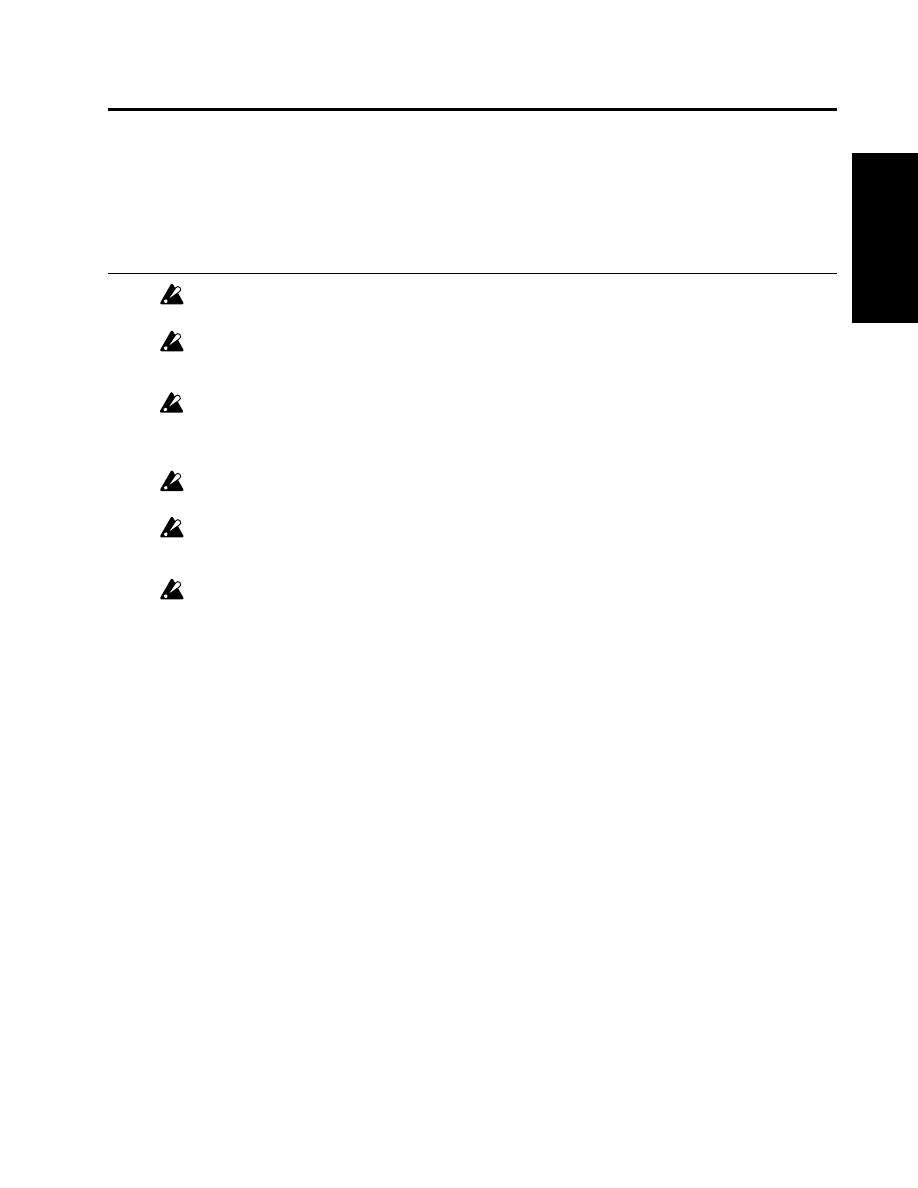
Each program of bank M has the following structure.
Oscillator section
This is the section which creates the waveform that is the basis of the sound.
These settings are made by the “Program Edit P1” and “Program Edit P2” parameters.
• OSC 1, 2
Thirteen methods of sound production (i.e., thirteen oscillator types) are provided. Two of these oscillator
types can be used together, and settings made to specify the basic pitch, etc. However depending on the
oscillator type, only one oscillator may be available.
These settings are made by the “1-2: OSC Basic,” “1-3: OSC 1 Pitch,” “1-4: OSC 2 Pitch,” and “2-1: OSC”
parameters.
• Sub oscillator
This lets you use one of four types of basic waveform. Pitch-related settings can be made in the same way
as OSC 1 and 2.
These settings are made by the “1-5: Sub Pitch” and “2-2: Sub/Noise” parameters.
• Noise generator
This generates white noise. The noise can be sent through a multi-mode filter (low pass filter, high pass
filter, band pass filter).
These settings are made by the “2-2: Sub/Noise” parameters.
Mixer section
The output of oscillators 1 and 2, the sub oscillator, and the noise generator are mixed with the feedback from
the amp section, and output to multi-mode filters 1 and 2 (the filter section).
These settings are made by the “3-1: Mixer” parameters.
Mixer
Oscillator 1
Oscillator 2
Sub Oscillator
Noise Generator
Feedback
Amp1
Amp2
Pan
LPF/HPF/BPF/BRF/2BPF
LPF/HPF/BPF/BRF/2BPF
Filter 1
Filter 2
Insert
Effect
Master
Effect
EQ
1/L/Mono
2/R
OSC Section
Mixer Section
Filter Section
AMP Section
FX Section
EG1
EG2
EG3
EG4
Amp.EG
LFO1 LFO2 LFO3 LFO4
Joy Stick, Ribbon Controller
& other controllers
3
4
Bank M Program Structure

Filter section
This section modifies the waveform by attenuating or emphasizing specific portions of the frequency spectrum.
It contains two multi-mode filters. Each filter can be set to one of the following types: low pass filter, high pass
filter, band pass filter, band reject filter, or dual band pass filter. This lets you modify the brightness of the
sound. You can also select the way in which the two filters will be connected with the mixer section and amp
section.
These settings are made by the “3-2: Filter 1,” “3-3: Filter 1 SUB,” “3-4: Filter 2,” and “3-5: Filter 2 SUB” parameters.
Amp section
This section modifies the volume of the output from the filter section. It contains two independent amplifiers.
The signal which is input to each amplifier will depend on how the two filters are connected. The amp section
also contains an amplitude envelope generator (Amp EG) which controls the amp.
These settings are made by the “4-1: Amp” and “4-2: Amp EG” parameters.
Effect section
This section applies effects to the signal which is output from the amp section. It has the same parameter structure
as the programs of other banks.
These settings are made by the “Program Edit P7” and “Program Edit P8” parameters.
EG section
This section provides four general-purpose envelope generator (EG) units. The four EG’s for which settings are
made in the EG section can be used as modulation sources for the parameters of each section, in order to apply
time-variant change to the sound.
These settings are made by the “Program Edit P5” parameters.
LFO section
This section provides four general-purpose LFO units. The four LFO’s for which settings are made in the LFO
section can be used as modulation sources for the parameters of each section, in order to apply cyclic change to
the sound.
These settings are made by the “Program Edit P6” parameters.
Program basic section
Settings are made here for the program name, category, scale, key assign, keyboard, and the control nctions
(joystick, ribbon controller, etc.).
These settings are made by the “1-1: Prog Basic” parameters.
Editing
Bank M
programs are similar to bank A and bank B programs, in the respect that they can be edited in Program
Play mode or by using the Performance Editor. One method to try is to use an existing program which resembles
the desired sound, and use Program Edit mode to edit the parametes.
T
he filter, amp, effect, EG and LFO sections will function in the same way as for banks they do inand B, but the
display page structure and the parameters are different (☞ “3. Parameters” in this manual).
The operation and parameters of the oscillator and mixer sections are unique to bank M programs.
Bank M Program Structure
Program Structure

Characteristics of each oscillator
For bank M sounds, OSC 1 provides thirteen oscillator types (methods of sound generation) and OSC 2 provides
nine types. In Program Edit P1 “1-2: OSC Basic” you can select one of these types for each oscillator, to specify
the combination.
If OSC 1 is set to an oscillator type of 01:Standard to 09:Electric Piano Model, you will also be able to select an
oscillator type of 01:Standard to 09:Electric Piano Model for OSC 2. If OSC 1 is set to an oscillator type of
10:Brass Model
to 13: Bowed String Model, OSC 2 will not be available for use.
01: Standard OSC
This simulates the oscillator of an analog synthesizer. It can produce the same effects as an analog synthesizer,
such as pulse width modulation (☞ page 14 of this manual).
02: Comb Filter OSC
This oscillator creates pitched sound from noise or an impulse. It can create a wide variety of sounds — not only
noisy sounds, but also sounds ranging from synth-bass to strings (☞page 7 of this manual).
03: VPM OSC (Variable Phase Modulation OSC)
This oscillator uses phase modulation to create overtones. By modulating the phase of two oscillators and using
a wave shaping table to process the sound, rich overtones can be produced (☞page 19 of this manual)
04: Resonance OSC
This oscillator uses four tunable filters which are set up in series. Noise is input through the filter bank for very
ethereal sounds (☞page 21 of this manual).
05: Ring Modulation OSC - This oscillator multiplies the modulator and carrier and outputs the
resultant signal.
06: Cross Modulation OSC - This oscillator uses a modulator to frequency-modulate a carrier.
07: Sync Modulation OSC (oscillator sync)
These are special oscillators which simulate the effect of two oscillators which are used to modulate each other,
which was a technique that was possible on analog synthesizers. These are especially suitable for producing
sounds that are rich in overtones, such as bells, metallic sounds or gongs (☞page 23, 24, 25 of this manual).
08: Organ Model
This simulates a drawbar organ with three drawbars (when one oscillator is used) or six drawbars (when two
oscillators are used) (☞page 26 of this manual). Since each drawbar can use one of four types of waveform, a
wide range of tones can be produced.
09: Electric Piano Model
This is a physical model which simulates a warm, vintage electric piano sound (☞page 8 of this manual).
10: Brass Model
This is a physical model which simulates a brass instrument such as a trumpet or trombone (☞page 30 of this
manual).
11: Reed Model
This is a physical model which simulates a wind instrument such as a saxophone or flute (☞page 33 of this
manual)
12: Plucked String Model
This is a physical model which simulates a plucked string instrument such as a guitar or bass guitar (☞page 36
of this manual).
13: Bowed String Model
This is a physical model which simulates a bowed string instrument (☞page 40 of this manual).
Bank M Program Structure
3. Parameters
This section explains the bank M parameters which are added when the MOSS-TRI DSP Synthesizer
Option
is installed (pre-installed in the Trinity V3 series). For details on parameters other than bank M,
refer to your Parameter Guide, Basic Guide, and Effect Guide.
Program Play Mode
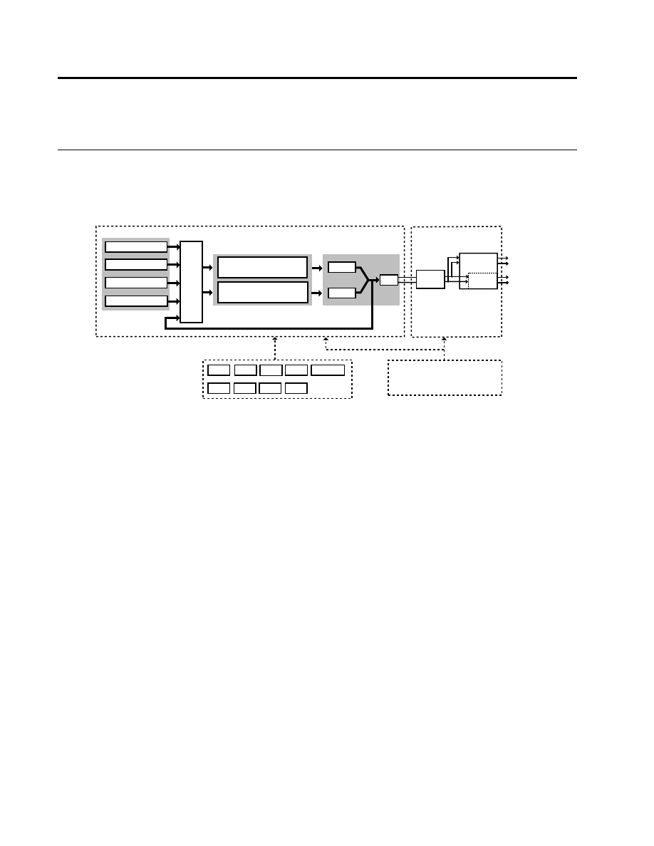
Program Play P1
1–1: Program Play
Here, you can select programs and perform simple editing.
For details on the parameters, refer to page 1 of your Parameter Guide: “1. Program Play mode.”
Depending on the oscillator type(s) used by the program or the combination of effect types, a brief interval
of time may be required before a newly-selected program actually begins operating after it is selected.
1-1: Prog Play
Parameters
Prog.
Play
P1
Program Edit Mode
The Write Program item in the page menu commands of each page lets you write an edited program to the
program number you specify.
Be sure to write an edited program that you wish to keep. If you turn off the power or select another
program before you write, the edited program cannot be recovered.
For details refer to Basic Guide page 23, “9. Writing a program or combination”.
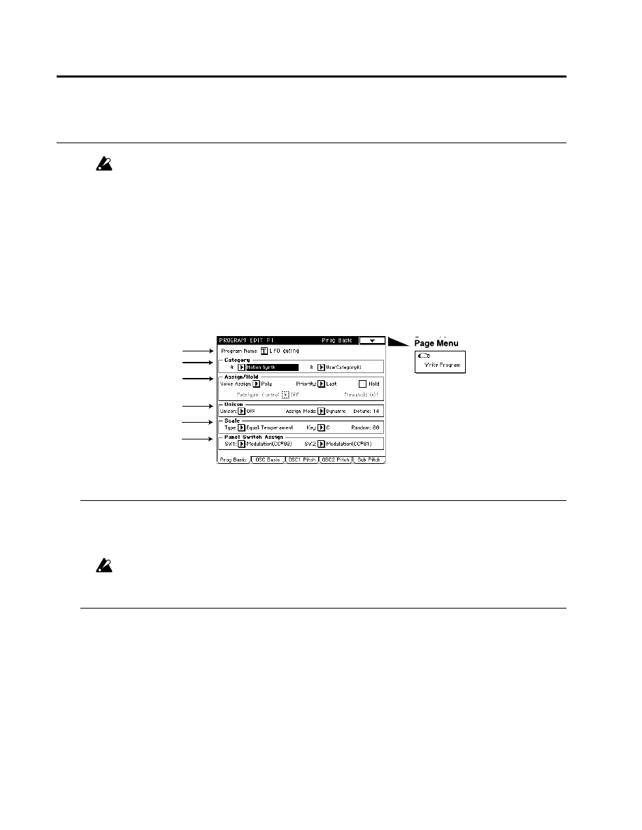
Program Edit P1
Here you can make basic settings for the program, and basic settings for the oscillator(s) that will be
used.
1–1: Prog Basic
1–1a: Program Name
This indicates the program that was selected in Program Play mode.
You can press the text edit button to access a window that allows you to rename the program (☞page
6 in Basic Guide).
When you wish to write a renamed program, be sure to use the Write Program operation (☞page 23 in Basic
Guide). If you select another program or turn off the power, the newly specified program name will be lost.
1–1b: Category
Two categories can be specified for each program.
When selecting programs in Program Play mode, Combination Play mode, or Sequencer mode, you
can use these categories to search for the desired program.
A (Category A)
[Keyboard…Drums/Perc.]
With the factory settings, these are listings of different types of instruments, but they can be changed in Global
mode “4-1: Category Program A” (☞page 128 in Parameter Guide).
B (Category B)
[User Category P01…P16]
The factory set category names can be changed in Global mode “4-2: Category Program B” (☞page 128 in
Parameter Guide).
1–1a
1–1b
1–1c
1–1d
1–1e
1–1f
1-1: Prog Basic

1–1c: Assign/Hold
Here, you can specify how notes will sound when keys are pressed.
Voice Assign
[Mono (Multi), Mono (Single), Poly]
Selects whether the sound will be played monophonically or polyphonically.
Mono (Multi):
Multi-triggered monophonic playing.
Mono (Single):
Single-triggered monophonic playing
Poly:
Polyphonic playing
When Poly is selected, the Retrigger Control and Threshold parameters will be unavailable.
Priority
[Last, Low, High]
Specifies the priority order that will be used when the number of keys pressed exceeds the maximum polyphony.
Last:
The last-pressed note will take priority
Low:
The lowest note will take priority
High:
The highest note will take priority
Hold
When this is checked, the note will continue to sound after the key is released. However, if the EG selected by
“4-1: Amp” (normally the Amp EG is used) has a sustain level of zero, the note will decay naturally.
Retrigger Control
[OFF…MIDI (CC#83)]
“Retrigger” refers to the action of resetting the EG and LFO at the time of note-on (the EG will return to its start
level, and the LFO will return to the beginning of the cycle of its waveform). Here you can select the controller
(Retrigger Controller ☞page 64 of this manual) which will specify whether or not the sound will be retriggered
when a note-on occurs.
Threshold (Retrigger Control Threshold)
[1…127]
Specifies the value at which EG and LFO will be retriggered by a note-on.
The state of the controller selected by Retrigger Control (i.e., whether the controller value is above or below the
specified Threshold value) will determine whether or not the sound will be retriggered when a note-on occurs.
The operation of this function will differ depending on the Voice Assign setting.
With a setting of Mono (Multi), retriggering will occur if the controller is below the threshold value. If Retrigger
Control is OFF, retriggering will always occur.
With a setting of Mono (Single), retriggering will occur if the controller is above the threshold value. If Retrigger
Control is OFF, retriggering will not occur.
If a note-on occurs when all notes are off, retriggering will always occur.
LFO’s whose Key Sync is turned OFF will not be reset even if retriggering occurs.
1–1d: Unison
Here, you can make settings for unison mode.
Unison
[OFF, 2voices, 3voices, 6voices]
Specifies the number of notes which will be sounded in unison. With a setting of OFF, unison will not be used.
The maximum polyphony will be three notes with a setting of 2voices, two notes for a setting of 3voices, and
one note for a setting of 6voices.
Mode
[Fixed, Dynamic]
Specifies how the number of voices specified by the Unison setting will be allocated.
With a setting of Fixed, the number of voices specified by the Unison setting will always sound. With a setting
of Dynamic, the number of voices will be determined by the current note-playing situation.
Detune
[0…99]
Detunes the notes that are sounded simultaneously by the Unison function.
1-1: Prog Basic
Parameters
Prog.
Edit
P1

1–1e: Scale
Specifies the scale type
Type (Scale Type)
[Equal Temperament…All Range User Scale]
Selects the basic scale for the internal tone generator. The user scales can be specified in Global mode “3-1: User
Scale” (☞page 127 in Parameter Guide).
Equal Temperament
The most widely used scale, consisting of equally-spaced semitone steps.
Pure Major
The major chords of the selected key will be perfectly in tune.
Pure Minor
The minor chords of the selected key will be perfectly in tune.
Arabic
This reproduces a quarter-tone scale of Arabic music.
Pythagorean
A scale based on ancient Greek musical theory, suitable for playing melodies.
Werckmeister (Werkmeister III)
An equal-tempered scale used in the later Baroque period.
Kirnberger (Kirnberger III)
A scale created in the 18th century, and used mainly for tuning harpsichords.
Slendro
An Indonesian gamelan scale in which the octave consists of 5 notes.
If the Key parameter is set to C, use the C, D, F, G, and A keys. (Other keys will produce the same pitches as
equal temperament.)
Pelog
An Indonesian gamelan scale in which the octave consists of 7 notes.
If the Key parameter is set to C, use only the white keys. (The black keys will produce the same pitches as
equal temperament.)
Octave User Scale
This is the one-octave scale that you create in Global mode “3-1b: Octave Notes” (☞page 127 in Parameter
Guide).
Stretch
This is a tuning used on acoustic pianos.
All Range User Scale
This is the full-range scale (C-1=G9) that you create in Global mode “3-1a: All Notes” (☞page 127 in Parameter
Guide).
Key (Scale Key)
[C…B]
Specifies the tonic note of the selected scale.
Random
[0…99]
As this value is increased, the pitch of the note will become increasingly unpredictable. Normally you will leave
this set at zero.
Adjust this parameter when you wish to simulate instruments whose pitch is naturally unstable, such as tape-
mechanism organs or acoustic instruments.
1-1: Prog Basic

1–1f: Panel Switch Assign
These parameters assign the function of the front panel SW1 and SW2 switches (assignable panel
switches 1 and 2).
SW1
[JS(X) Lock…Modulation (CC#80)]
SW2
[JS(X) Lock…Modulation (CC#81)]
The functions which can be assigned to SW1 and SW2 are the same (except for Modulation), and are as follows:
JS(X) Lock, JS(+Y) Lock, JS(–Y) Lock, Ribbon(X) Lock, Ribbon(Z) Lock, After Touch Lock, JS & Ribbon Lock
Each time you press SW1 (or SW2), the selected controller will alternate between Lock/Unlock (a lit LED
indicates Lock). When you press SW1 (or SW2) while operating a controller, subsequent movement of that
controller will produce no change.
For example if you select JS(+Y) Lock, and then move the joystick away from yourself and press SW1 (or
SW2
), the joystick (+Y) movement will be locked (held) at that position, and modulation will continue to be
applied even after the joystick is allowed to return. By then moving the joystick in the (–Y) direction, you
can apply both types of modulation simultaneously.
If this is locked, the corresponding controller will also stop transmitting MIDI, but reception will still
occur.
Octave Down
Each time you press SW1 (or SW2), the original octave setting will alternate with a setting of one octave
lower.
Octave Up
Each time you press SW1 (or SW2), the original octave setting will alternate with a setting of one octave
higher.
Portamento Off
Each time you press SW1 (or SW2), the portamento effect will alternate between On and Off (lit LED indicates
Off
). This is valid only for bank M programs.
CC#65
will be transmitted each time On/Off occurs (a value of 0 for Off, 127 for On).
Modulation
Select this when you wish to use the switch as a AMS or Effect Dynamic Modulation source. In this case, you
must first specify the control destination.
SW1 and SW2 differ for this function alone. For each On/Off, SW1 will transmit CC#80 , and SW2 will
transmit CC#81 (a value of 0 for Off, 127 for On).
AMSource
AMSource
MIDI
MIDI
MIDI
Parameters
Prog.
Edit
P1
1-1: Prog Basic
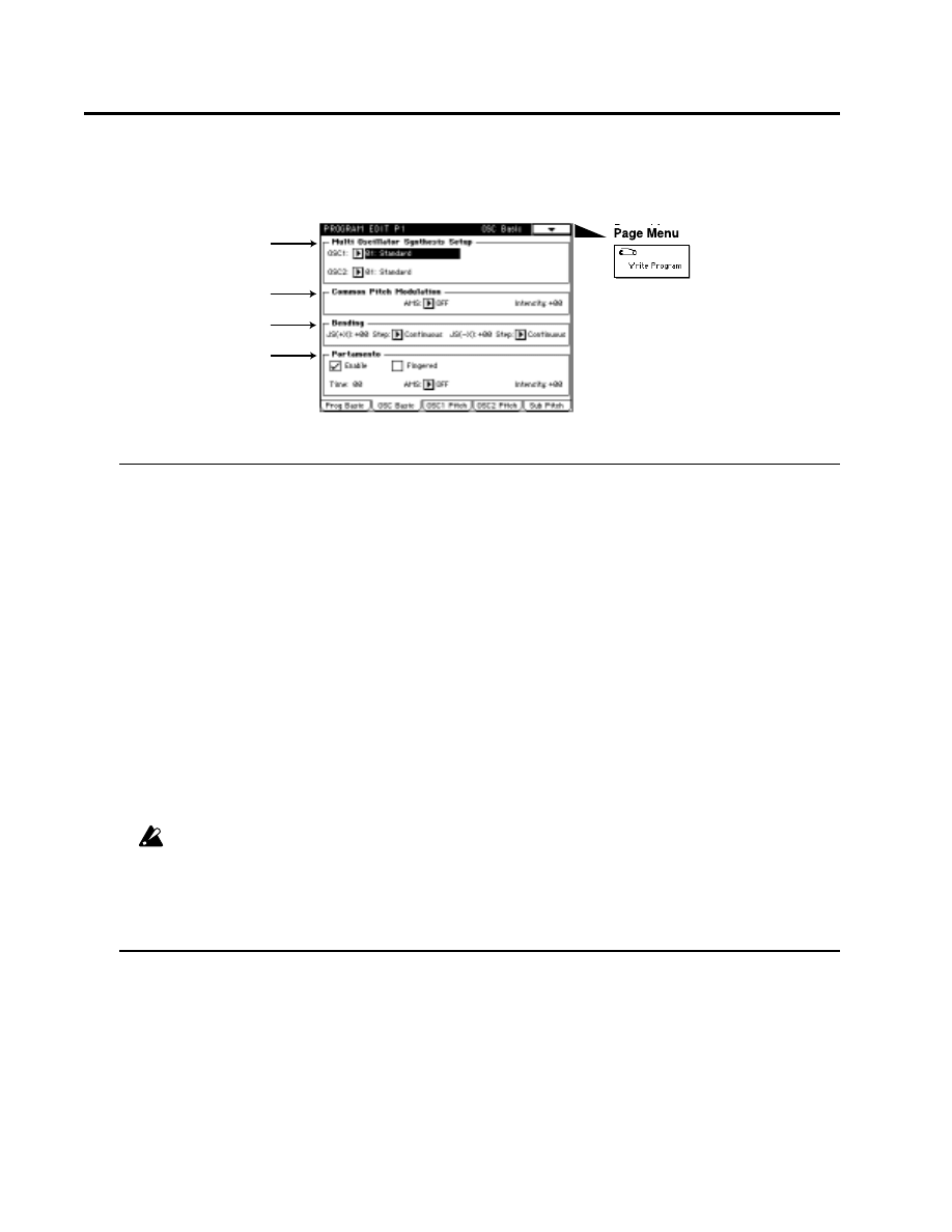
1–2: OSC Basic
1–2a: Multi Oscillator Synthesis Setup
Here, you can make settings for the oscillator.
The parameters that are set in “2-1: OSC 1” and “2-2: OSC 2” will differ depending on the oscillator
type that is selected here.
OSC 1 (Oscillator 1 Type)
[01: Standard…13: Bowed String Model]
Selects the oscillator type for oscillator 1.
01: Standard
02: Comb Filter
03: VPM (Variable Phase Modulation OSC)
04: Resonance
05: Ring Modulation
06: Cross Modulation
07: Sync Modulation
08: Organ Model
09: Electric Piano Model
10: Brass Model
11: Reed Model
12: Plucked String Model
13: Bowed String Model
When 10: Brass Model, 11: Reed Model, 12: Plucked String Model, or 13: Bowed String Model are selected,
OSC 2 cannot be used.
OSC 2 (Oscillator 2 Type)
[01: Standard…09: Electric Piano Model]
Selects the oscillator type for oscillator 2. Refer to OSC 1.
1–2b: Common Pitch Modulation
Creates time-varying changes in the pitch of all oscillators (oscillators 1 and 2, and the sub oscillator).
AMS (Alternate Modulation Source)
[OFF…MIDI (CC#83)]
Selects the modulation source (☞page 64 of this manual) that will control the pitch of all oscillators (oscillators
1 and 2, and the sub oscillator).
Intensity (Common Pitch AMS Intensity)
[–99…+99]
Specifies the depth and direction of the effect produced by AMS.
1–2a
1–2b
1–2c
1–2d
1-2: OSC Basic
1–2c: Bending
Specifies the width of pitch change that will occur when the joystick is moved to left and right.
JS(+X) (Joystick Intensity +X)
[–60…+24]
Specifies the amount and direction of pitch change (in semitone units) that will occur when the joystick is
moved to the right.
With positive (+) settings the pitch will rise, and with negative (-) settings the pitch will fall. A setting of 12 will
produce one octave of change.
Step (Joystick Step +X)
[Continuous, 1/8, 1/4, 1/2, 1…12]
Specifies how the pitch will change when the joystick is moved to the right.
Continuous: Smooth change.
1/8:
Change in 1/8 semitone steps.
1/4:
Change in 1/4 semitone steps.
1/2:
Change in 1/2 semitone steps.
1...12:
Change in steps of the specified number of semitones (up to 1 octave).
JS(–X) (Joystick Intensity –X)
[–60…+24]
Specifies the amount and direction of pitch change (in semitone units) that will occur when the joystick is
moved to the left.
Step (Joystick Step –X)
[Continuous, 1/8, 1/4, 1/2, 1…12]
Specifies how the pitch will change when the joystick is moved to the left.
Refer to Step (Joystick Step +X).
If the Step (Joystick Step +X) or Step (Joystick Step –X) settings are greater than the settings for JS (+X) and
JS (–X), the pitch will not change.
1–2d: Portamento
These settings specify how portamento will be applied. (Portamento creates a smooth change in pitch
from one note to the next.) The setting you make here is valid only if Enable is checked.
Enable
Check
this when you wish to use portamento.
Fingered
Check
this when you want to apply portamento only when a note is pressed while continuing to hold the
previous note.
Time
[0…99]
Specifies the portamento time. Higher values will cause the pitch to change more slowly.
AMS (Alternate Modulation Source)
[OFF…MIDI (CC#83)]
Selects a modulation source (☞page 64 of this manual) that will control “Time.”
Intensity (Portamento Time AMS Intensity)
[–99…+99]
Specifies the way in which the portamento time will be controlled by the “AMS .”
1-2: OSC Basic
Parameters
Prog.
Edit
P1
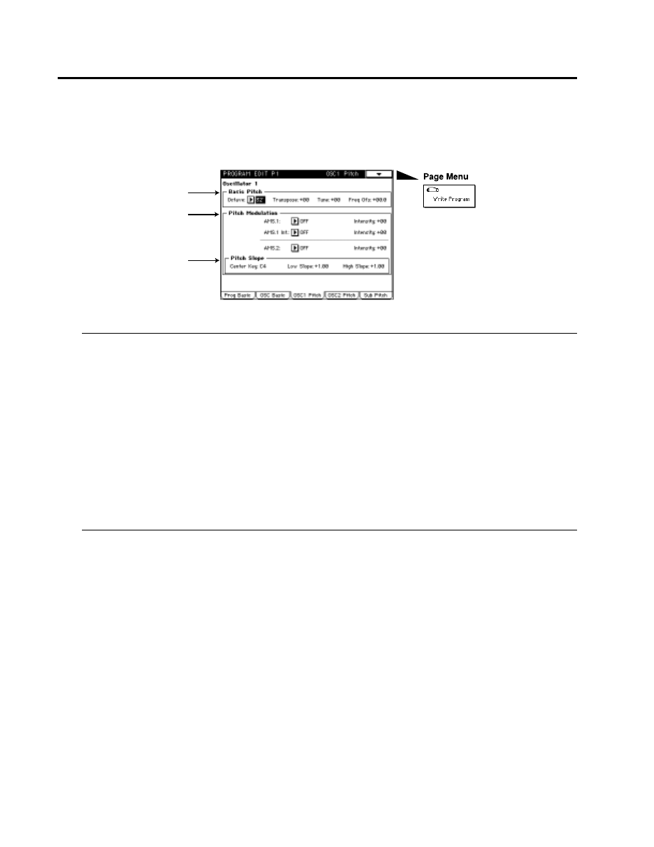
1–3: OSC 1 Pitch
Here, you can make settings for the basic pitch of oscillator 1, pitch modulation, and pitch slope.
1–3a: Basic Pitch
Specifies the basic pitch of oscillator 1
Octave
[32'…4']
Specifies the basic pitch of oscillator 1 in steps of an octave. 32' is two octaves below, 16' is one octave below, 8'
is standard pitch, and 4' is one octave above.
Transpose
[–12…+12]
Adjusts the basic pitch specified by “Octave” in semitone steps.
Tune
[–50…+50]
Makes fine adjustments to the pitch in one-cent steps.
Frequency Ofs
[–10.0…+10.0]
Makes fine adjustments to the pitch in 0.1 Hz steps.
1–3b: Pitch Modulation
Specifies the pitch Modulation.
AMS.1 (Alternate Modulation Source 1)
[OFF…MIDI (CC#83)]
Selects a modulation source 1 (☞page 64 of this manual) which will modify the pitch (e.g., apply vibrato).
Intensity (Pitch AMS.1 Intensity)
[–99…+99]
Specifies the depth and direction of the pitch change that will be controlled by “AMS.1.”
AMS.1 Int (AMS.1 Intensity Alternate Modulation Source)
[OFF…MIDI (CC#83)]
Specifies the controller (☞page 64 of this manual) that will control the “Intensity (Pitch AMS.1 Intensity).”
Intensity (AMS.1 Int AMS Intensity)
[–99…+99]
Specifies the depth of the pitch modulation effect controlled by “AMS.1 Int .”
1–3a
1–3b
1–3c
1-3: OSC 1 Pitch

AMS.2 (Alternate Modulation Source 2)
[OFF…MIDI (CC#83)]
Selects a modulation source 2 (☞page 64 of this manual) which will modify the pitch (e.g., apply vibrato).
Intensity (Pitch AMS.2 Intensity)
[–99…+99]
Specifies the depth and direction of the pitch change that will be controlled by “AMS.2.”
1–3c: Pitch Slope
Specifies how pitch will change in relation to the keyboard (key)
Center Key
[C–1…G9]
Specifies the key at which Lower/Higher keyboard tracking will begin to apply.
Low Slope
[–1.00…+2.00]
Specify the depth and direction of the pitch change that will occur for notes below the “Center Key.”
High Slope
[–1.00…+2.00]
Specifies the depth and direction of the pitch change that will occur for notes above the Center Key.
When Low Slope and High Slope are set to +2.0, playing one octave upward from the Center Key will cause the
pitch to rise two octaves.
With a setting of –1.0, playing one octave upward will cause the pitch to fall one octave. With a setting of 0.0, the
notes in the respective areas will produce the same pitch as the Center Key. To play pitches normally, set this
parameter to +1.0.
1–4: OSC 2 Pitch
Here, you can make settings for the oscillator type, basic pitch, pitch keyboard tracking, and pitch
modulation of oscillator 2. The parameters of oscillator 2 are the same as for oscillator 1. (Refer to the
explanation of the “1–3: OSC 1 Pitch” page).
1–5: Sub Pitch
Here, you can make settings for the oscillator type, basic pitch, pitch keyboard tracking, and pitch
modulation of sub oscillator . The parameters of sub oscillator are the same as for oscillator 1. (Refer
to the explanation of the “1–3: OSC 1 Pitch” page).
1-3: Osc1 Pitch, 1-4: OSC2 Pitch, 1-5: Sub Pitch
Parameters
Prog.
Edit
P1
C-1
C4
C9
C-1
C9
Pitch
Key
Center Key
Int=-1.0
Int=+2.0
Int=+1.0
Int=0.0
Program Edit P2
Here, you can make settings for each oscillator type. The oscillator type is specified in “1-2a: Multi
Oscillator Synthesis Setup” of “1-2: OSC Basic.”
The display pages that appear will depend on the selected oscillator type.
2–1: OSC
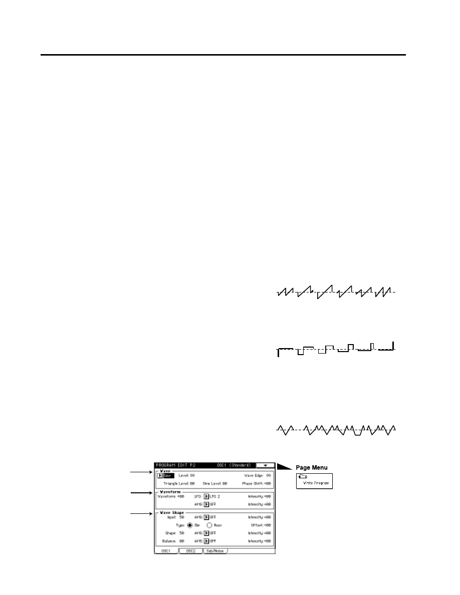
01: Standard
This oscillator produces the waveforms used by an analog synthesizer (sawtooth wave, pulse wave,
triangle wave) and sine wave. Sawtooth wave, pulse wave and triangle wave waveforms can be
modified using waveform modulation. You can specify either sawtooth wave or pulse wave as the
main waveform, and mix triangle wave or sine wave with this for output. The level of these three
waveforms can be adjusted independently. In addition, wave shaping can be applied to the output of
this oscillator.
Waveform modulation
Pulse width modulation (PWM) on an analog synthesizer produces time-varying change in the pulse width of a pulse
wave. The waveform modulation provided by the MOSS-TRI option is an extension of this, which varies not only the
pulse width but also the waveform of a sawtooth wave or triangle wave. Waveform modulation will affect the various
waveforms as follows.
Sawtooth wave
Waveform modulation will modify a sawtooth waveform as
shown below, creating time-variant change in the sound.When
modulation is 0, the basic sawtooth waveform will be produced,
and when it is 99, a sawtooth wave of double the frequency will
be produced. If the modulation value is a negative number, a
different effect will result than with positive settings.
Pulse wave
Waveform (pulse width) modulation will modify a pulse
waveform as shown below, creating time-variant change in the
sound. When modulation is 0, a square wave will be produced,
and when it is 99, the pulse width will be 0, meaning that there
will be no sound. If the modulation value is a negative number,
the results will be inverted.
Triangle wave
Waveform modulation will modify a ramp wave as shown below, creating time-variant change in the sound.
When modulation is 0, a triangle wave will result, and as the modulation value increases, the waveform will
become a ramp wave (a waveform in which the slope is broken in two). At a modulation value of 50, a trapezoidal
wave will result, and at a value of 99 the waveform will once again
be a triangle wave. If the modulation value is a negative number,
the results will be inverted.Compared to sawtooth or pulse waves,
this waveform produces a strong fundamental with fewer
overtones, making it particularly suitable for bass sounds etc.
-99
-33
0
33
66
99
-98
-33
0
33
66
98
-99
-25
0
25
50
75
99
2–1a
2–1b
2–1c
2:1 OSC 1 (01: Standard)
2–1a: Wave
Main Wave
[Saw, Pulse]
Selects the main waveform. Select either Saw (sawtooth wave) or Pulse (pulse wave).
Level
[0…99]
Specifies the output level of the main waveform.
Wave Edge
[0…99]
Adjusts the amount of high-range overtones for the main waveform. As the pitch rises, this effect will become
stronger, and in the low range there will be little effect. Lower settings of this parameter will produce a more mellow
sound, and in the vicinity of 0 the volume will also decrease.
Triangle Level
[0…99]
Specifies the output level of the triangle waveform. It will be output mixed with the main waveform.
Sine Level
[0…99]
Specifies the output level of the sine waveform. It will be output mixed with the main waveform.
Phase Shift (Triangle & Sine Phase Shift)
[–99…+99]
Specifies the phase difference between the main waveform and the triangle and sine waveforms. (The triangle
and sine waveforms will always be in phase with each other.)
2–1b: Waveform(Waveform Modulation)
Waveform
[–99…+99]
Specifies the waveform. For the way in which this value will affect the waveform, refer to the diagrams shown
on the previous page for sawtooth wave, pulse wave, and triangle wave.
LFO
[LFO1…LFO4]
Selects the source LFO for waveform modulation. LFO settings are made in the “Program Edit P6.”
Intensity (Waveform Modulation LFO Intensity)
[–99…+99]
Specifies the depth and direction of the waveform modulation that will be controlled by the LFO specified in
“LFO.”
AMS (Alternate Modulation Source)
[OFF…MIDI (CC#83)]
Selects a modulation source (☞page 64 of this manual) that will control “Waveform.”
Intensity (Waveform AMS Intensity)
[–99…+99]
Specifies the depth and direction of the waveform modulation controlled by the “AMS.” For negative settings,
the polarity of the modulation source will be inverted.
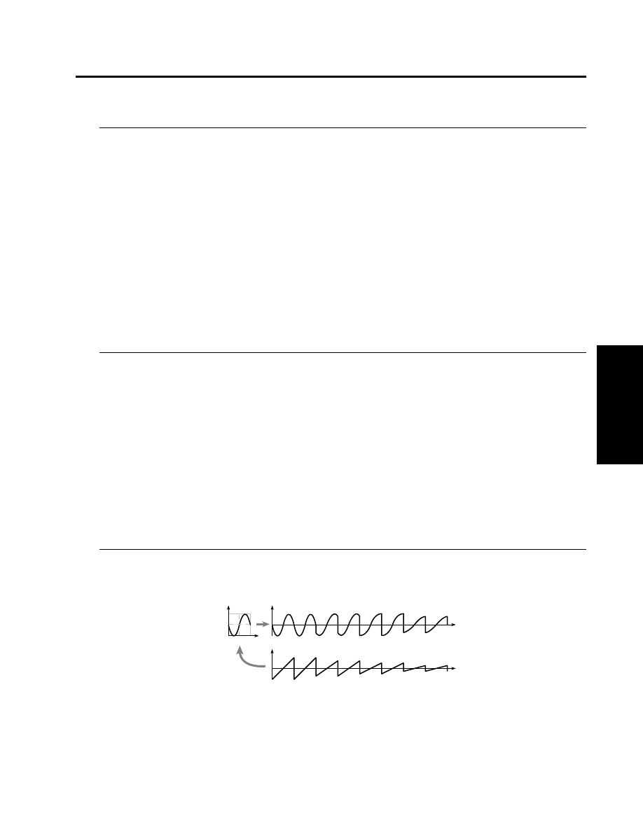
2–1c: Wave Shape
Input (Input Level)
[0…99]
Specifies the level of the signal that is input from the standard oscillator to the wave shaping table.
AMS (Alternate Modulation Source)
[OFF…MIDI (CC#83)]
Selects a modulation source (☞page 64 of this manual) that will control “Input.”
Intensity (Input Level AMS Intensity)
[–99…+99]
Specifies the depth and direction of the waveform modulation controlled by the “AMS.”
Output level
Input level
Input waveform
Output waveform
Example of when Input Level is modified (Table Type : Reso)
Input Level
=99
Input Level
=75
Input Level
=50
Input Level
=25
2:1 OSC 1 (01: Standard)
Parameters
Prog.
Edit
P2
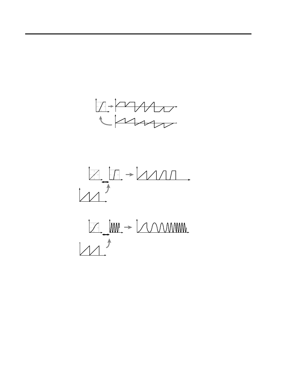
2:1 OSC 1 (01: Standard)
Type (Wave Shape Table Type)
[Clip/Reso]
Use the radio buttons to select the wave shaping table which will modify the input waveform.
Clip (clip type) and Reso (resonant type) tables will modify the waveform as shown by the diagrams in Shape,
below.
Offset (Wave Shape Offset)
[–99…+99]
Specifies an offset amount that will be added to the signal specified by “Input.”
Shape
[0…99]
Specifies the characteristics of the table which will modify the input waveform. The characteristics of the table
will change as follows.
AMS (Alternate Modulation Source)
[OFF…MIDI (CC#83)]
Selects a modulation source (☞page 64 of this manual) that will control “Shape.”
Intensity (Shape AMS Intensity)
[–99…+99]
Specifies the depth and direction of the waveform modulation controlled by the “AMS.”
Balance
[0…99]
Specifies the balance between the signal that has passed through the wave shaping table and the output signal
from the standard oscillator. With a setting of 99, it will be only the output of the wave shaping table.
AMS (Alternate Modulation Source)
[OFF…MIDI (CC#83)]
Selects a modulation source (☞page 64 of this manual) that will control “Balance.”
Intensity (Balance AMS Intensity)
[–99…+99]
Specifies the depth and direction of the waveform modulation controlled by the “AMS.”
Output level
Input level
Input waveform (Input Level fixed)
Output waveform
Example of when Offset is modified (Table Type: Clip)
Offset=50
Offset=0
Offset=-50
Output level
Input
level
Shape of the wave shaping table and the Shape parameter
CLIP type
Output of the clip type table when a sawtooth
waveform is input
Waveform
level
Waveform before being input to the table
Shape:0
Shape:99
Output level
Input
level
Resonant type
Output of the resonance type table when
a sawtooth wave is input
Waveform
level
Waveform before being input to the table
Shape:0
Shape:99
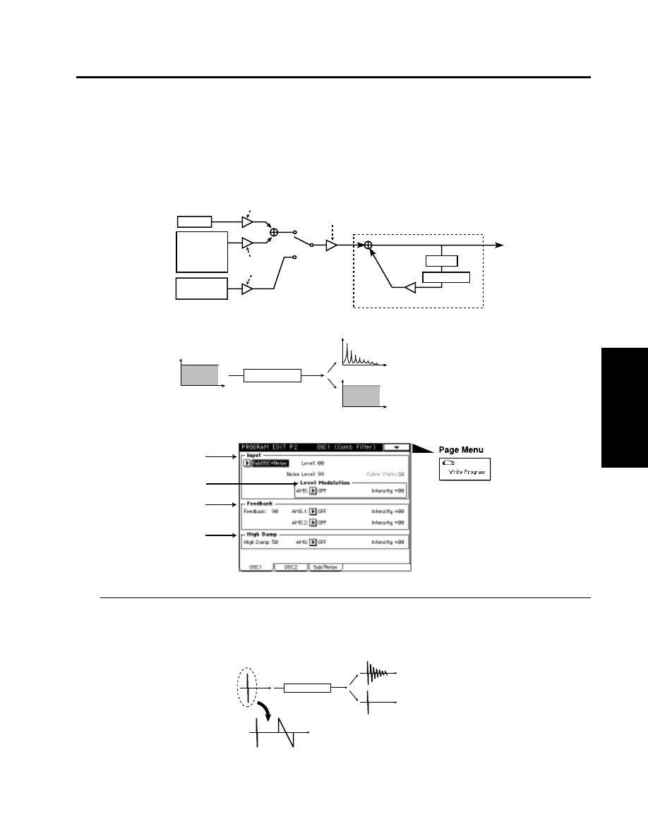
2:1 OSC 1 (02: Comb Filter)
Parameters
Prog.
Edit
P2
02: Comb Filter
In this oscillator, the signal from the other oscillator waveform or the noise generator is sent through
a comb filter, and the feedback level of the comb filter is varied in order to produce tonal change.
When noise is input, raising the feedback of the comb filter will gradually change the sound into a
pitched tone.
2–1a: Input
Input
[OSC2(1)+Noise, SubOSC+Noise, Filter1+Noise, Filter2+Noise, Pulse Noise, Impulse]
Selects the signal that will be input to the comb filter.
Frequency
Example of when noise is input
Level
As the Feedback value increases,
the sound will become more pitched.
Delay
Comb Filter Feedback
Comb Filter
High Damp
Noise Level
Input Wave
Level
Noise
Pulse Noise
or Impulse
Comb Oscillator
Comb Filter
Feedback=0
Feedback>0
Input Level Mod.Source/Intensity
OSC1/2 or
Sub OSC
Filter1 out
Filter2 out
Level
Level
Frequency
Frequency
2–1a
2–1c
2–1d
2–1b
Example of when an Impulse is input
As the Feedback is
increased, the decay
time will become longer.
Time
Time
Comb Filter
Pluse
Width=0
Pluse
Width=99
Feedback=0
Feedback>0
Time
Time

2:1 OSC 1 (02: Comb Filter)
Level (Input Wave Level)
[0…99]
Specifies the volume level of the signal that will be input to the comb filter.
Noise Level
[0…99]
This parameter will be available only if “Input” has been set to OSC2(1)+Noise, SubOSC+Noise, Filter1+Noise
or Filter2+Noise. It specifies the volume level of the noise generator output which will be input to the comb
filter.
Pulse Width
[0…99]
This parameter will be available only if “Input” has been set to Pulse Noise or Impluse. It specifies the length
of time that the Pulse Noise or Impluse will last after being triggered.
2–1b: Level Modulation
AMS (Alternate Modulation Source)
[OFF…MIDI (CC#83)]
Selects a modulation source (☞page 64 of this manual) that will control the volume level of the signal being
input to the comb filter. The volume level is set by the “Level” or the “Noise Level.”
Intensity (Input Wave Level AMS Intensity)
[–99…+99]
Specifies the depth and direction of the effect of “AMS.”
2–1c: Feedback
Feedback
[0…99]
Specifies the amount of feedback for the comb filter. If this value is high, the resonance of the comb filter will be
high, and the tone will have a clear sense of pitch. Conversely, if this value is low, the input signal will be
output without change, and if the input signal is only noise, the output signal will have no sense of pitch.
AMS.1 (Alternate Modulation Source 1)
[OFF…MIDI (CC#83)]
Selects a modulation source 1 (☞page 64 of this manual) that will control “Feedback.”
Intensity (Feedback AMS.1 Intensity)
[–99…+99]
Specifies the depth and direction of the effect of “AMS.1 .”
AMS.2 (Alternate Modulation Source 2)
[OFF…MIDI (CC#83)]
Selects a modulation source 2 (☞page 64 of this manual) that will control “Feedback.”
Intensity (Feedback AMS.2 Intensity)
[–99…+99]
Specifies the depth and direction of the effect of “AMS.2 .”
2–1d: High Damp
High Damp
[0…99]
Specifies the amount of attenuation that will be applied to the high-frequency component of the feedback signal
within the comb filter.
As this value is increased, the tone will become more mellow. Conversely, decreasing this value will produce
a brighter tone.
AMS (Alternate Modulation Source)
[OFF…MIDI (CC#83)]
Selects a modulation source (☞page 64 of this manual) that will control “High Damp.”
Intensity (High Damp AMS Intensity)
[–99…+99]
Specifies the depth and direction of the effect of “AMS.”
2:1 OSC 1 (03: VPM)
Parameters
Prog.
Edit
P2
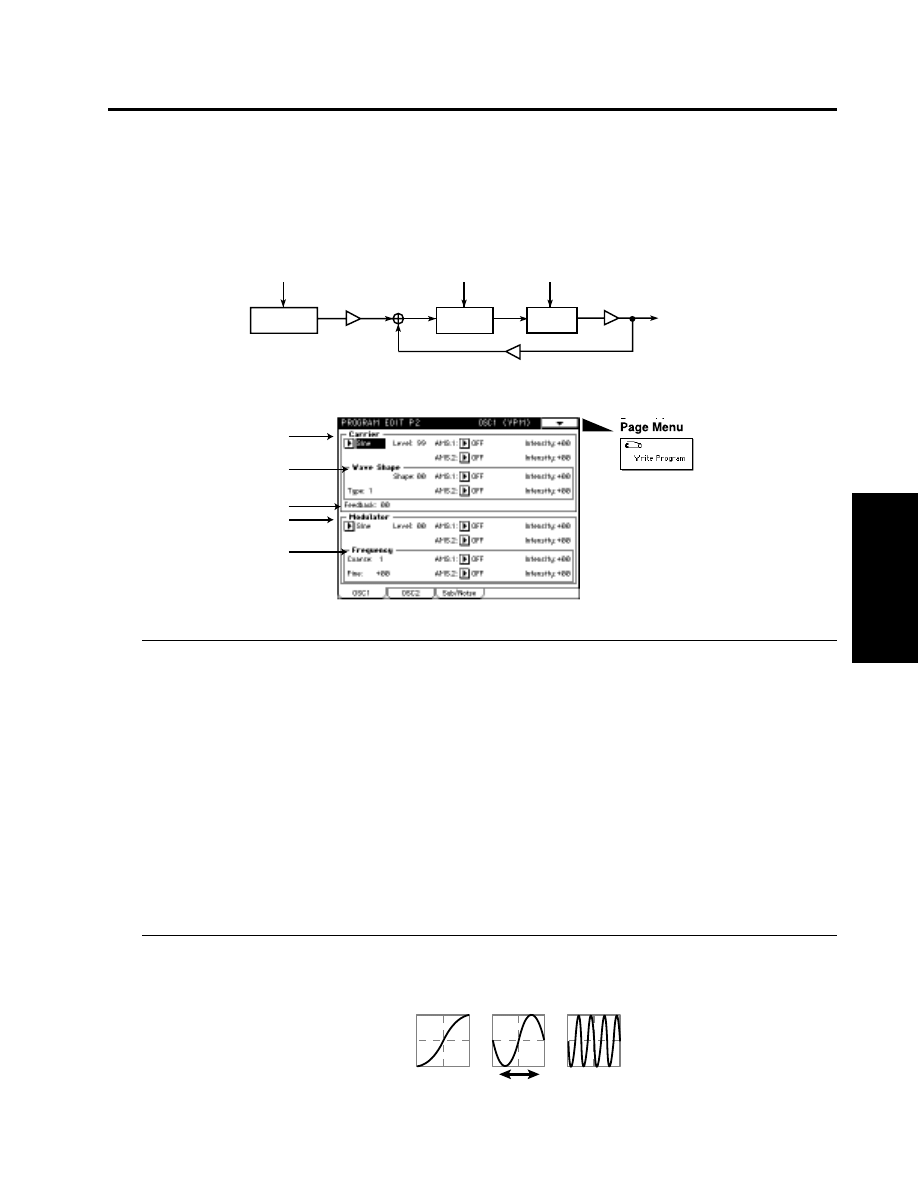
03: VPM
The output of a carrier is phase-modulated by a modulator, and output through wave shape processing.
By controlling the wave shaping parameters and the feedback gain, tonal changes that are different
than simple phase modulation can be produced.
2–1a: Carrier
Wave
[Saw, Square, Triangle, Sine]
Selects the carrier waveform.
Level
[0…99]
Specifies the output level of the carrier. This will determine the output level of the VPM oscillator.
AMS.1 (Alternate Modulation 1 Source)
[OFF…MIDI (CC#83)]
Selects a modulation source 1 (☞page 64 of this manual) that will control “Level.”
Intensity (Level AMS.1Intensity)
[–99…+99]
Specifies the depth and direction of the effect of “AMS.1.”
AMS.2 (Alternate Modulation 2 Source)
[OFF…MIDI (CC#83)]
Selects a modulation source 2 (☞page 64 of this manual) that will control “Level.”
Intensity (Level AMS.2 Intensity)
[–99…+99]
Specifies the depth and direction of the effect of “AMS.2.”
2–1b: Wave Shape
Shape
[0…99]
Specifies the number of cycle of wave shaping. As this value is increased, the number of cycles will increase,
causing more overtones to be added to the high-frequency range of the sound.
2-1a
2–1b
2–1c
2–1d
2–1e
Modulator Pitch
Carrier Pitch
(Basic Pitch)
Carrier Level
Output
Wave Shape Parameter
Feedback Gain
Modulator Level
Modulator
Carrier
Wave
Shape
Table valiation
Shape:0
Shape:99
Table Variation

2:1 OSC 1 (02: Comb Filter)
AMS.1 (Alternate Modulation Source 1)
[OFF…MIDI (CC#83)]
Selects a modulation source 1 (☞page 64 of this manual) that will control “Shape” value.
Intensity (Shape AMS.1 Intensity)
[–99…+99]
Specifies the depth and direction of the effect of “AMS.1.”
AMS.2 (Alternate Modulation Source 2)
[OFF…MIDI (CC#83)]
Selects a modulation source 2 (☞page 64 of this manual) that will control “Shape” value.
Intensity (Shape AMS.2 Intensity)
[–99…+99]
Specifies the depth and direction of the effect of “AMS.2.”
Type (Wave Shap Type)
[1, 2]
1
: The signal after wave shaping will be output without further change. If “Shape” is set to the
minimum value, the phase modulated signal will be output essentially without change.
2
: A rounded waveform will be obtained regardless of the “Shape” value.
2–1c: Feedback
[0…99]
Specifies the amount of the output after wave shaping that will be fed back to the carrier.
2–1d: Modulator
Wave
[Saw, Square, Triangle, Sine, OSC2(1), SubOSC, Filter1, Filter2]
Selects the modulator waveform.You may select the other oscillator or the sub oscillator, etc.
If you select OSC 2(1), SubOSC, Filter 1, or Filter 2, it will not be possible to set “2-1e: Frequency.”
Level
[0…99]
Specifies the output level of the modulator.
This value will determine the amount of modulation that is applied to the “2-1a: Carrier” setting.
AMS.1 (Alternate Modulation Source 1)
[OFF…MIDI (CC#83)]
Selects a modulation source 1 (☞page 64 of this manual) that will control “Level.”
Intensity (Level AMS.1 Intensity)
[–99…+99]
Specifies the depth and direction of the effect of “AMS.1.”
AMS.2 (Alternate Modulation Source 2)
[OFF…MIDI (CC#83)]
Selects a modulation source 2 (☞page 64 of this manual) that will control “Level.”
Intensity (Level AMS.2 Intensity)
[–99…+99]
Specifies the depth and direction of the effect of “AMS.2.”
2–1e: Frequency
Coarse
[0.5, 1…16]
Specifies a multiplication factor which will be applied to the pitch of the modulator, relative to the “2-1a: Carrier”
setting.
Fine
[–50…+50]
Makes fine adjustments to the pitch of the modulator.
AMS.1 (Alternate Modulation Source 1)
[OFF…MIDI (CC#83)]
Selects a modulation source 1 (☞page 64 of this manual) that will control the pitch of the modulator.
Intensity (Frequncy AMS.1 Intensity)
[–99…+99]
Specifies the depth and direction of the effect of “AMS.1.”
AMS.2 (Alternate Modulation Source 2)
[OFF…MIDI (CC#83)]
Selects a modulation source 2 (☞page 64 of this manual) that will control the pitch of the modulator.
Intensity (Frequncy AMS.2 Intensity)
[–99…+99]
Specifies the depth and direction of the effect of “AMS.2.”
2:1 OSC 1 (04: Resonance)
Parameters
Prog.
Edit
P2
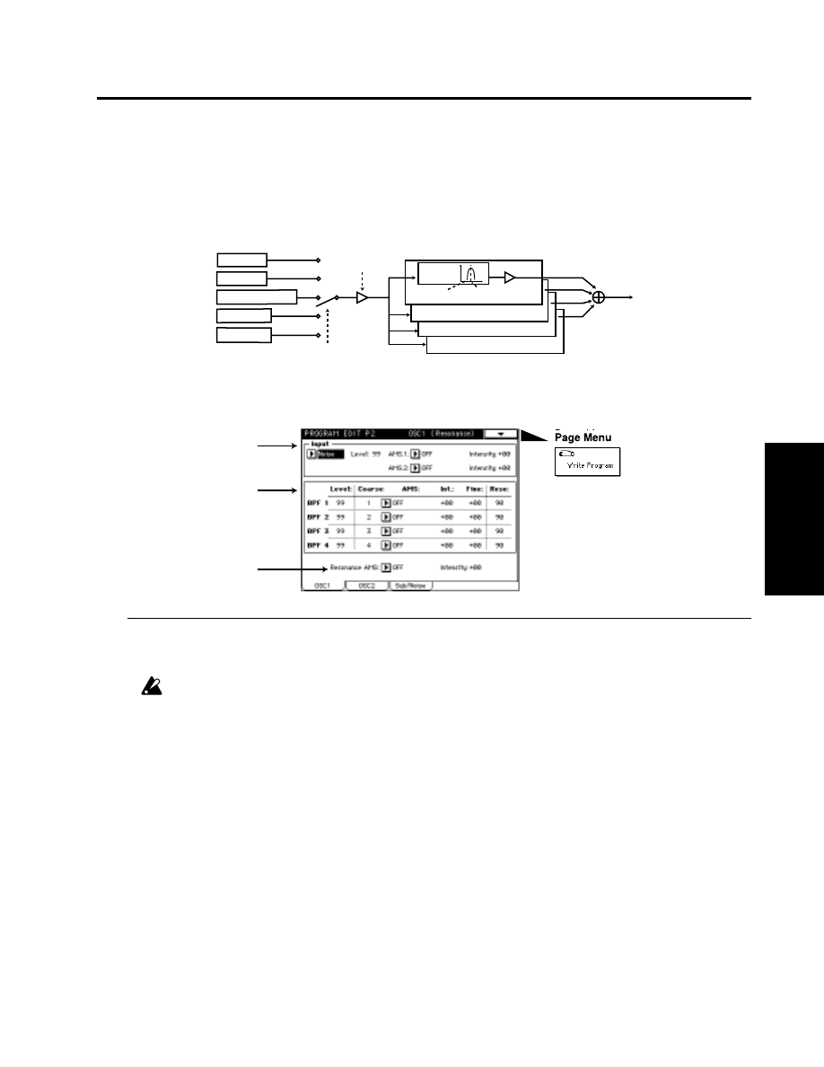
04: Resonance
This oscillator produces a wide range of tonal change by allowing you to specify the cutoff frequency
and resonance of four band pass filters (BPF). You can select one of the following sources to be the
input for the filters: the output of the other oscillator, the sub-oscillator, the output of the noise
generator, or the output of filter 1 or filter 2.
2–1a: Input
Input
[OSC2(1), SubOSC, Noise, Filter1, Filter2]
Selects the signal that will be input to the four band bass filters.
If you select 04:Resonance for OSC 1 and 2 in “1-2a: Multi Oscillator Synthesis Setup,” and select the other
oscillator as the input for each, the result will be unstable — the sound may be non-reproduceable, or you
may hear no sound at all.
Level
[0…99]
Specifies the level of the signal that is input to the four band pass filters.
AMS.1 (Alternate Modulation Source 1)
[OFF…MIDI (CC#83)]
Selects a modulation source 1 (☞page 64 of this manual) that will control “Level.”
Intensity (Level AMS.1 Intensity)
[–99…+99]
Specifies the depth and direction of the effect of “AMS.1.”
AMS.2 (Alternate Modulation Source 2)
[OFF…MIDI (CC#83)]
Selects a modulation source 2 (☞page 64 of this manual) that will control “Level.”
Intensity (Level AMS.2 Intensity)
[–99…+99]
Specifies the depth and direction of the effect of “AMS.2.”
2–1a
2–1b
2–1c
OSC 1/2
Sub OSC
Noise Generator
BPF2
BPF3
BPF4
BPF1
Resonance1 Coarse1
Level1
Input Level
Input Select
Filter1 out
Filter2 out

2–1b: BPF1…4
Here, you can make settings for each band pass filter 1—4.
Level
[0…99]
Specifies the output level.
Coarse
[1…16]
Specifies the harmonic (overtone) of the oscillator pitch at which the center frequency of the filter will be located.
You can specify from the first to the 16th harmonic.
AMS (Alternate Modulation Source)
[OFF…MIDI (CC#83)]
Selects a modulation source (☞page 64 of this manual) that will control Coarse.
Int. (BPF Frequency AMS Intensity)
[–15…+15]
Specifies the depth and direction of the effect of AMS. Positive (+) settings will allow the Coarse value to be
increased, and negative (–) settings will allow the Coarse value to be decreased. At this time, the center frequency
of band pass filter 1 will change in steps of harmonics, creating the impression that the pitch is changing step-
wise.
Fine
[–99…+99]
Makes fine adjustments to the center frequency of band pass filter 1 specified by the Coarse parameter.
Reso
[0…99]
Specifies the resonance. Increasing this value will produce a stronger effect.
2–1c: Resonance
Resonance AMS (Resonance Alternate Modulation Source)
[OFF…MIDI (CC#83)]
Selects a modulation source (☞page 64 of this manual) that will control the resonance that was specified for
each band pass filter.
Intensity (Resonance AMS Intensity)
[–99…+99]
Specifies the depth and direction of the effect of “Resonance AMS.”
2:1 OSC 1 (04: Resonance)
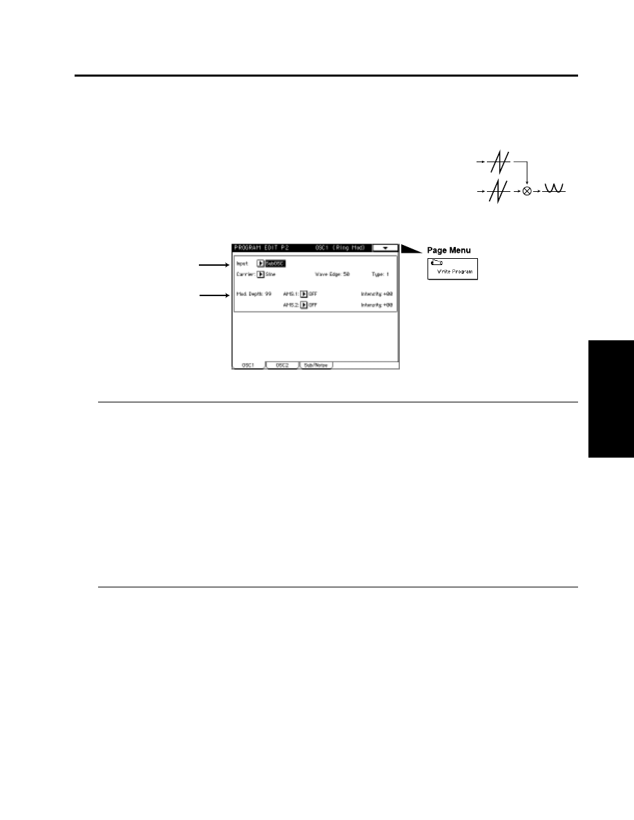
05: Ring Modulation
This multiplies the modulator and carrier and outputs the signal
produced. One of four types of waveform can be selected as the
carrier. Since the result will be a metallic sound with little sense of
pitch, this is suitable for producing sound effects. The Ring
Modulation oscillator contains an internal carrier oscillator. The
output of the other oscillator etc. can be selected as the modulator.
2–1a: Input
Input
[OSC2(1), SubOSC, Noise, Filter1, Filter2]
Specifies the modulator.
If you select 05:Resonance for OSC 1 and 2 in “1-2a: Multi Oscillator Synthesis Setup,” and select the other
oscillator as the Input for each, you may hear no sound at all for some parameter settings.
Carrier
[Saw, Square, Triangle, Sine]
Specifies the carrier waveform.
Wave Edge
[0…99]
Specifies the amount of high frequency harmonics for the carrier waveform. As this value is decreased, the
sound will have less high-frequency harmonics, and as it approaches 0 the volume will also decrease.
Type
[1, 2]
Selects the modulation type. The two types differ in the tone of the high range. Type 2 will produce a brighter
sound than type 1.
2–1b: Mod. Depth
Mod. Depth
[0…99]
Specifies the depth of modulation. At a setting of 0, the carrier waveform will be output without change.
AMS.1 (Alternate Modulation Source 1)
[OFF…MIDI (CC#83)]
Selects a modulation source 1 (☞page 64 of this manual) that will control “Mod. Depth.”
Intensity (Modulation Depth AMS.1 Intensity)
[–99…+99]
Specifies the depth and direction of the effect of “AMS.1.”
AMS.2 (Alternate Modulation Source 2)
[OFF…MIDI (CC#83)]
Selects a modulation source 2 (☞page 64 of this manual) that will control “Mod. Depth.”
Intensity (Modulation Depth AMS.2 Intensity)
[–99…+99]
Specifies the depth and direction of the effect of “AMS.2.”
2:1 OSC 1 (05: Ring Modulation)
Parameters
Prog.
Edit
P2
Ring Modulation
Modulator
Carrier Wave
2–1a
2–1b
2:1 OSC 1 (06: Cross Modulation)
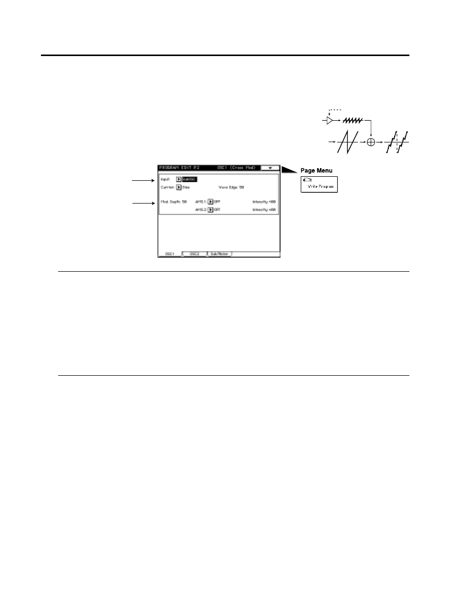
06: Cross Modulation
This uses a modulator to frequency-modulate a carrier. You
can select one of four waveforms as the carrier. In general, a
pitch envelope is applied to the modulator. A carrier oscillator
is built-in to the Cross Modulation OSC. You can select the
output of the other oscillator etc. as the modulator.
2–1a: Input
Input
[OSC2(1), SubOSC, Noise, Filter1, Filter2]
Specifies the modulator.
Carrier
[Saw, Square, Triangle, Sine]
Specifies the carrier waveform.
Wave Edge
[0…99]
Specifies the amount of high frequency harmonics for the carrier waveform. As this value is decreased, the
sound will have less high-frequency harmonics, and as it approaches 0 the volume will also decrease.
2–1b: Mod. Depth
Mod. Depth
[0…99]
Specifies the depth of modulation. At a setting of 0, the carrier waveform will be output without change.
AMS.1 (Alternate Modulation Source 1)
[OFF…MIDI (CC#83)]
Selects a modulation source 1 (☞page 64 of this manual) that will control “Mod. Depth.”
Intensity (Modulation Depth AMS.1 Intensity)
[–99…+99]
Specifies the depth and direction of the effect of “AMS.1.”
AMS.2 (Alternate Modulation Source 2)
[OFF…MIDI (CC#83)]
Selects a modulation source 2 (☞page 64 of this manual) that will control “Mod. Depth.”
Intensity (Modulation Depth AMS.2 Intensity)
[–99…+99]
Specifies the depth and direction of the effect of “AMS.2.”
Cross Modulation
Cross Modulation Depth
Modulator
Carrier Wave
2–1a
2–1b
2:1 OSC 1 (07: Sync Modulation)
Parameters
Prog.
Edit
P2
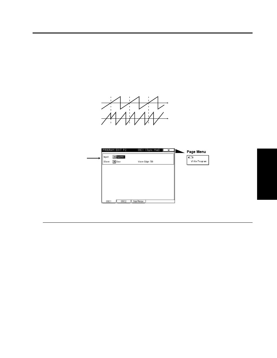
07: Sync Modulation
This uses the modulator as the master waveform and the carrier as the slave waveform (which will be
synchronized to the master).
When the master waveform begins a new cycle (i.e., the instant that it passes the zero point going
from negative to positive), the phase of the slave waveform is reset to 0, causing it to begin a new
cycle.
2–1a: Input
Input
[OSC2(1), SubOSC, Noise, Filter1, Filter2]
Specifies the master waveform (modulator).
Slave
[Saw, Square, Triangle, Sine]
Specifies the slave waveform.
Wave Edge
[0…99]
Specifies the amount of high frequency harmonics for the slave waveform. As this value is decreased, the
sound will have less high-frequency harmonics, and as it approaches 0 the volume will also decrease.
Modulator Wave
(Master)
Carrier Wave
(Slave)
Sync Modulation
2–1a
2:1 OSC 1 (08: Organ Model)
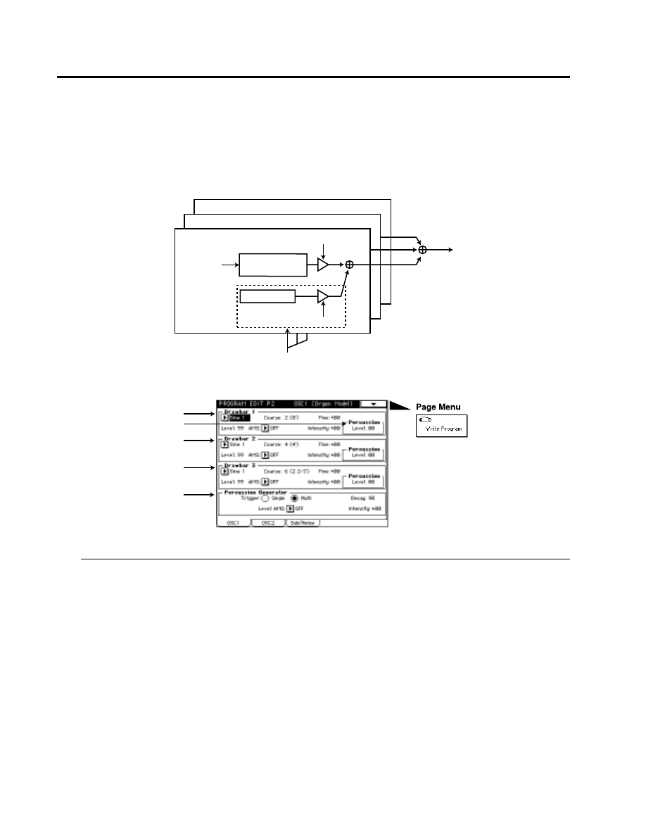
08: Organ Model
This is an oscillator used to produce organ-type sounds. The oscillator simulates three drawbars
similar to electric organs of the past.
You can specify the footage [Harmo] and waveform setting for each drawbar, allowing a wide range
of sounds to be created.
2–1a: Drawbar 1
Wave
[Sine 1, Sine 2, Sine 3, Triangle]
Specifies the waveform for drawbar 1. Sine 1 contains only the fundamental (i.e., a pure sine wave). Sine 2 and
Sine 3
are waveforms which contain the first two and the first three harmonics respectively.
Coarse (Harmonics Coarse)
[1…16]
Specifies the pitch of drawbar 1, relative to one octave below the oscillator pitch.
Fine (Harmonics Coarse Fine)
[–99…+99]
Makes fine adjustments to the pitch of drawbar 1.
Level
[0…99]
Specifies the volume level of drawbar 1.
AMS (Alternate Modulation Source)
[OFF…MIDI (CC#83)]
Selects a modulation source (☞page 64 of this manual) that will control the “Level” of drawbar 1.
Intensity (Level AMS Intensity)
[–99…+99]
Specifies the depth and direction of the effect of “AMS.1.”
Wave
Sine1 or Sine2
/Sine3/Triangle
Harmonics
(Pitch)
Level
Drawbar1
Drawbar2
Drawbar3
Percussion Level
Precussion
Precussion
Decay/Level Mod.
2–1a
2–1c
2–1d
2–1e
2–1b

2:1 OSC 1 (08: Organ Model)
Parameters
Prog.
Edit
P2
2–1b: Percussion Level
[0…99]
Specifies the volume level of the percussion effect for drawbar 1.
2–1c: Drawbar 2
The parameters are structured identically to those of “2-1a: Drawbar 1.” Refer to “2-1a: Drawbar 1”
and “2-1b: Percussion Level.”
2–1d: Drawbar 3
The parameters are structured identically to those of “2-1a: Drawbar 1.” Refer to “2-1a: Drawbar 1”
and “2-1b: Percussion Level.”
2–1e: Percussion Generator
Trigger
[Single/Multi]
Use the radio buttons to specify how the percussion effect will be triggered.
With a setting of Single, the percussion effect will apply to the first-played note from a condition of no sound.
With a setting of Multi, the percussion effect will apply to each note that is played.
Decay
[0…99]
Specifies the decay length of the percussion. As this value is increased the decay time will become longer.
Level AMS (Level Alternate Modulation Source)
[OFF…MIDI (CC#83)]
Selects a modulation source (☞page 64 of this manual) that will control the percussion level of each drawbar.
Intensity (Level AMS Intensity)
[–99…+99]
Specifies the depth and direction of the effect of “Level AMS” on the percussion level.
2:1 OSC 1 (09: Electric Piano Model)
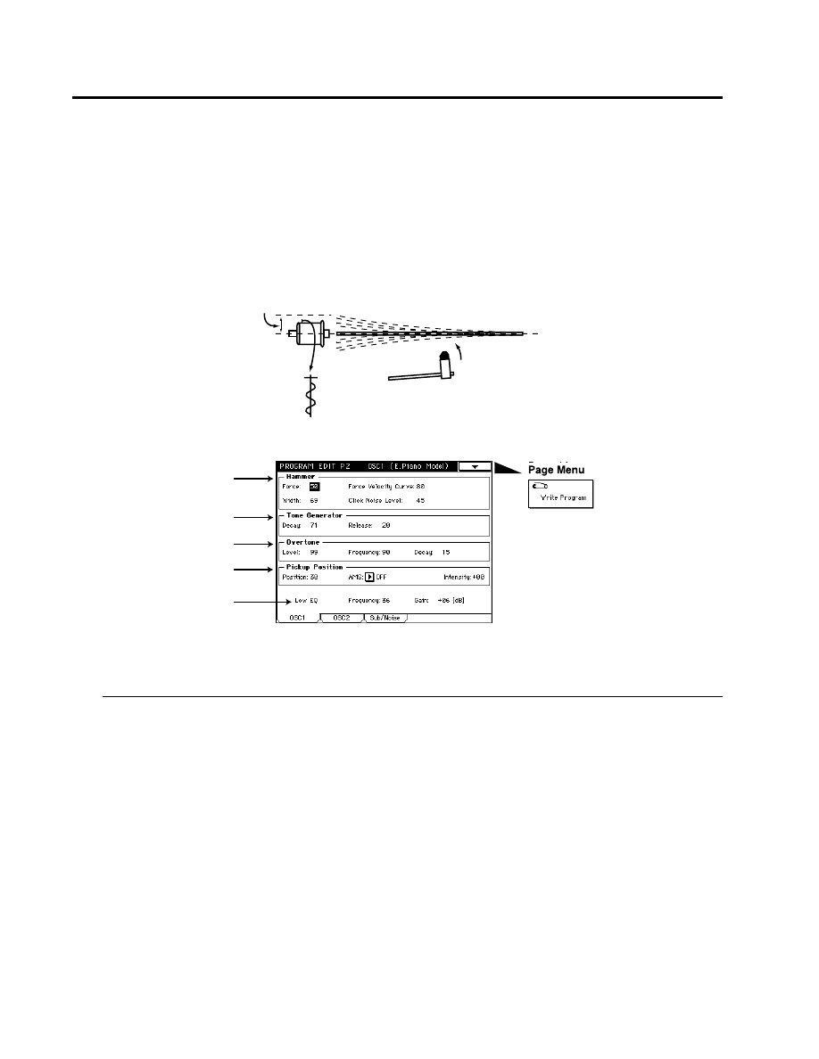
09: Electric Piano Model
This oscillator simulates an electric piano.
There are four groups of parameters: Hammer (which specifies how the shape and motion of the
hammer will affect tonal change and attack noise), Tone Generator (which vibrates in response to
being struck by the hammer), Pickup (which specifies the tonal change that occurs when the vibration
of the tone generator is converted into an electrical signal), and Low EQ (which is a shelving-type
low EQ to adjust the low range).
2–1a: Hammer
Force
[0…99]
Specifies the “Strength” with which the hammer strikes the tone generator. Higher settings will produce a
brighter sound.
Force Velocity Curve
[OFF, 0…99]
Specifies how changes in velocity will affect “Force.” As this value is increased, velocity will have a greater
effect on “Force,” allowing more dynamic tonal change to be produced. With a setting of OFF, the “Force” will
be constant.
Width (Hammer Width)
[0…99]
Simulates the shape of the hammer. As this value is increased, the width of the hammer will become narrower,
and the sound of the tone generator and hammer noise will become sharper.
Click Noise Level
[0…99]
Specifies the volume of the hammer noise that occurs at the attack.
Pickup
Tone Generator
Hammer
Pickup Position
to Low EQ
2–1a
2–1b
2–1c
2–1d
2–1e

2:1 OSC 1 (09: Electric Piano Model)
Parameters
Prog.
Edit
P2
2–1b: Tone Generator
The Decay and Release that you specify here will control the output level of the oscillator. In order
for these settings to have an effect, they must be set longer than the decay and release of the EG which
you are using for the Amp.
Decay
[0…99]
Specifies the decay time of the tone generato.
Release
[0…99]
Specifies the release time of the tone generator.
2–1c: Overtone
Level
[0…99]
Specifies the volume of the higher overtones that are produced when the tone generator vibrates.
Frequency
[0…99]
Specifies the frequency of the overtones.
Decay
[0…99]
Specifies the decay time of the overtone volume.
2–1d: Pickup Position
Position
[0…99]
Specifies the location of the pickup in relation to the tone generator. With low settings, the pickup will be
placed in the center of the vertical vibration of the tone generator, causing the second partial to be emphasized
and the fundamental to be less audible.
AMS (Alternate Modulation Source)
[OFF…MIDI (CC#83)]
Selects a modulation source (☞page 64 of this manual) that will control “Position.”
Intensity (Pickup Position AMS Intensity)
[–99…+99]
Specifies the depth and direction of the effect of “AMS.”
2–1e: Low EQ
Makes settings for a Low EQ (shelving type) that will adjust the output signal.
Frequency (EQ Frequency)
[0…49]
Specifies the cutoff frequency of the Low EQ (shelving type) that will be applied to the output signal.
Gain
[–18…+18]
Specifies the gain of the Low EQ.
2:1 OSC 1 (10: Brass Model)
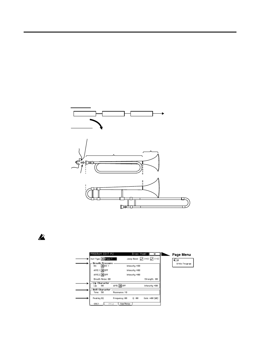
10: Brass Model
This oscillator is a physical model which simulates lip-reed instruments such as a trumpet or trombone.
By using key velocity or modulation wheel to modulate the Pressure (the force of breath blown into
the mouthpiece) you can produce performance expressions that are very similar to those of an actual
lip-reed instrument. The parameters are as follows: Inst Type determines the model which simulates
the bore length and shape of the instrument, Breath Pressure indicates the force of breath that is
blown into the mouthpiece, Lip Character produces the tonal changes that result from lip position or
tension, Bell Character produces the tonal changes that result from the shape of the end of the bore,
and Peaking EQ performs a final tonal adjustment.
This oscillator allows you to choose from two types of pitch bending: jump bending using a mode
jump as on a trumpet (by varying the bore length), and smooth bending produced by sliding the
length of the bore as on a trombone.
For some parameter settings, the pitch may not change according to the notes that are played on the keyboard.
In some cases, high-pitched notes may have a lower volume, or may not sound at all.
Lip (Character)
Specify tonal change produced by lip position
Inst Type
Select a model which simulates
the bore length and shape of
various instruments
Bell
Specify the shape
of the end of the bore
Specify the force of breath that is blown into the mouthpiece
Specify the amount of breath noise
Pressure
Noise
{
Brass Model
Signal Flow
Brass Model
Peaking EQ
Strength
2–1a
2–1b
2–1c
2–1d
2–1e

2:1 OSC 1 (10: Brass Model)
Parameters
Prog.
Edit
P2
2–1a: Inst Type
Inst Type
[Brass 1, Brass 2, Brass 3, Horn 1, Horn 2, Reed Brass]
Selects the instrument type which will determine the bore length and shape of the simulated instrument.
Jump Bend (+X)
Specifies how the pitch will change when the joystick is moved in the +X direction (toward the right).
If this is checked, the pitch will rise by in steps by changing the resonance of the bore, as on a trumpet.
If this is unchecked, the pitch will rise smoothly, as on most synthesizers.
Jump Bend (–X)
Specifies how the pitch will change when the joystick is moved in the –X direction (toward the left).
If Jump Bend (+X) and Jump Bend (–X) are checked, notes may not sound depending on the position of the
joystick and the pitch range setting.
For details on setting the pitch range of the joystick, refer to “1-2c: Bending.”
2–1b: Breath Pressure
EG
[EG 1…EG 4, Amp EG]
Selects the EG which will control pressure.
For details on the settings for each EG, refer to “Program Edit P5” for EG 1—4, and “4-2: Amp EG” for Amp EG.
Intensity (Pressure EG Intensity)
[–99…+99]
Specifies the depth and direction of the effect that the “EG” will have on the pressure.
AMS.1 (Alternate Modulation Source 1)
[OFF…MIDI (CC#83)]
Selects a modulation source 1 (☞page 64 of this manual) that will control pressure. If you select After Touch,
pressing down on the keyboard will produce the effect of the instrument being blown strongly. If you select Joy
Stick(X)
, rotating the Joy Stick in the + direction will produce this effect. In this case, setting “Intensity (Pressure
EG Intensity)” to 0 will allow you to completely control the breath pressure by operating the specified controller.
Intensity (Pressure AMS.1 Intensity)
[–99…+99]
Specifies the depth and direction of the change in pressure controlled by “AMS.1.”
AMS.2 (Alternate Modulation Source 2)
[OFF…MIDI (CC#83)]
Selects a modulation source 2 (☞page 64 of this manual) that will control pressure.
Intensity (Pressure AMS.2 Intensity)
[–99…+99]
Specifies the depth and direction of the change in pressure controlled by “AMS.2.”
Breath Noise
[0…99]
Specifies the volume level of the breath noise. Since this uses the signal from the noise generator, the filter of the
noise generator can be used to modify the tone of the noise.
Strength
[0…99]
Adjusts the tone. Higher settings of this value will produce a overdriven sound.
2–1c: Lip Character
Lip
[0…99]
Specifies the tonal change that is produced by lip position and tension. Higher settings of this value will produce a
harder (more firmly blown) sound. Lower settings will produce a softer tone.
AMS (Alternate Modulation Source)
[OFF…MIDI (CC#83)]
Selects a modulation source (☞page 64 of this manual) that will control “Lip.”
Intensity (Lip Character AMS Intensity)
[–99…+99]
Specifies the depth and direction of the effect of “AMS.”

2:1 OSC 1 (10: Brass Model)
2–1d: Bell Character
Tone
[0…99]
Specifies the tone of the bell. As this value is increased, the low frequency portion will disappear, producing a
less solid tone.
Resonance
[0…99]
Specifies the level at which the frequency region in the area of the “Tone” will be boosted. As this value is
increased
, the resonance effect will become stronger.
2–1e: Peaking EQ
Frequency
[0…49]
Specifies the center frequency of the frequency range that will be boosted or attenuated by the Peaking EQ.
Increasing this value
will raise the center frequency.
Q
[0…29]
Specifies the width of the Peaking EQ frequency band. Increasing this value will narrow the frequency band
that is boosted or attenuated.
Gain
[–18…+18]
Specifies the amount by which the area specified by “Frequency” and “Q” will be boosted or attenuated.
2:1 OSC 1 (11: Reed Model)
Parameters
Prog.
Edit
P2
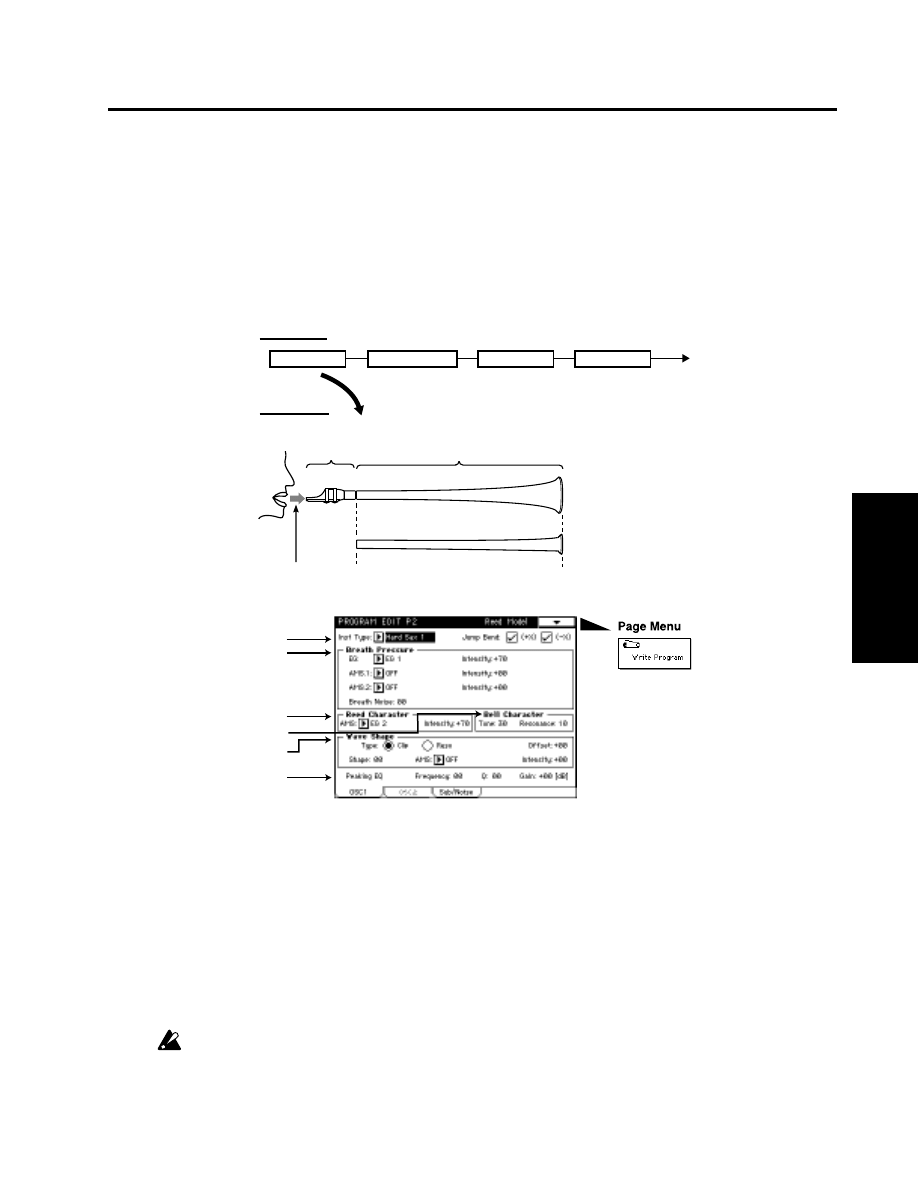
11: Reed Model
This oscillator is a physical model which simulates woodwind reed instruments such as a saxophone
or oboe.
By using key velocity or the modulation wheel to control Pressure (the strength with which the reed
is blown), you can use performance expressions that are very close to those of an actual woodwind
instrument. Also, by modulating the characteristics of the reed, you can produce tonal changes that
correspond with the way in which a reed is blown.2–1a: Inst Type
Inst Type
[Hard Sax 1...Reed Synth]
Selects the type of instrument whose bore shape and reed characteristics will be simulated.
Hard Sax 1, Hard Sax 2, Hard Sax 3, Soft Sax 1, Soft Sax 2, Double Reed 1, Double Reed 2, Bassoon, Clarinet, Flute 1, Flute
2, Pan Flute, Ocarina, Shakuhachi, Harmonica 1, Harmonica 2, Reed Synth
Jump Bend (+X)
Specifies how the pitch will change when the joystick is moved in the +X direction (toward the right).
If this is checked, the pitch will rise in steps by changing the resonance of the bore, as on a flute.
If this is unchecked, the pitch will rise smoothly, as on most synthesizers.
Jump Bend (–X)
Specifies how the pitch will change when the joystick is moved in the –X direction (toward the left).
If Jump Bend (+X) and Jump Bend (–X) are checked, notes may not sound depending on the position of the
joystick and the pitch range setting.
For details on setting the pitch range of the joystick, refer to “1-2c: Bending.”
Inst Type
Select a model to specify the bore length
and shape of the instrument to be simulated
Reed Character
Specify the vibrational
characteristics of the reed
Presure Specify the force of the breath that is blown into the reed
Noise Specify the amount of breath noise
{
Reed Model
Bell Character
Wave Shape
Reed Model
Signal Flow
Peaking EQ
2–1a
2–1b
2–1c
2–1d
2–1e
2–1f

2:1 OSC 1 (11: Reed Model)
2–1b: Breath Pressure
EG
[EG 1…EG 4, Amp EG]
Selects the EG which will control pressure.
For details on the settings for each EG, refer to “Program Edit P5” for EG 1—4, and “4-2: Amp EG” for Amp EG.
Intensity (Pressure EG Intensity)
[–99…+99]
Specifies the depth and direction of the effect that the EG will have on the pressure.
AMS.1 (Alternate Modulation Source 1)
[OFF…MIDI (CC#83)]
Selects a modulation source 1 (☞page 64 of this manual) that will control pressure. If you select After Touch,
pressing down on the keyboard will produce the effect of the instrument being blown strongly. If you select Joy
Stick (X)
, moving the joy stick toward the right will produce this effect.
Intensity (Pressure AMS.1 Intensity)
[–99…+99]
Specifies the depth and direction of the change in pressure controlled by AMS.1.
AMS.2 (Alternate Modulation Source 2)
[OFF…MIDI (CC#83)]
Selects a modulation source 2 (☞page 64 of this manual) that will control pressure.
Intensity (Pressure AMS.2 Intensity)
[–99…+99]
Specifies the depth and direction of the change in pressure controlled by AMS.2.
Breath Noise
[0…99]
Specifies the volume level of the breath noise.
Since this uses the signal from the noise generator, the filter of the noise generator can be used to modify the
tone of the noise.
2–1c: Reed Character
AMS (Alternate Modulation Source)
[OFF…MIDI (CC#83)]
Selects a modulation source (☞page 64 of this manual) that will modulate the characteristics of the reed.
Intensity (Reed AMS Intensity)
[–99…+99]
Specifies the depth of the modulation effect that “AMS” will have on the reed.
2–1d: Bell Character
Tone
[0…99]
Specifies the tone of the bell. As this value is increased, the low frequency portion will disappear, producing a
less solid tone.
Resonance
[0…99]
Specifies the level at which the frequency region in the area of the “Tone” will be boosted. As this value is
increased
, the resonance effect will become stronger.
2–1e: Wave Shape
Type (Wave Shape Table Type)
[Clip/Reso]
Use the radio buttons to select the wave shaping table which will modify the input waveform. For the way in
which the table will modify the waveform, refer to the Wave Shape diagram shown in 01: Standard (☞page 16
of this manual).
Offset
[–99…+99]
Specifies the offset value that will be added to the Reed OSC signal that is input to wave shaping.

2:1 OSC 1 (11: Reed Model)
Parameters
Prog.
Edit
P2
Shape
[0…99]
Specifies the character of the table that will shape the input waveform. For details on how the waveform will
change, refer to the “Wave Shape” diagram (☞page 16 of this manual) for the 01: Standard OSC.
AMS (Alternate Modulation Source)
[OFF…MIDI (CC#83)]
Selects a modulation source (☞page 64 of this manual) that will control “Wave Shape.”
Intensity (Shape AMS Intensity)
[–99…+99]
Specifies the depth and direction of the effect of “AMS.”
2–1f: Peaking EQ
Frequency
[0…49]
Specifies the center frequency of the range that will be boosted or attenuated by the Peaking EQ. Increasing this
value
will raise the center frequency.
Q
[0…29]
Specifies the width of the Peaking EQ frequency band. Increasing this value will narrow the frequency band
that is boosted or attenuated.
Gain
[–18…+18]
Specifies the amount by which the range specified by “Frequency” and “Q” will be boosted or attenuated.
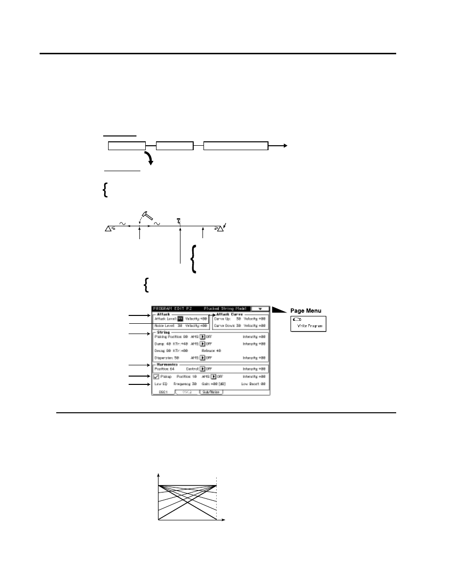
12: Plucked String Model
This oscillator is a physical model which simulates plucked string instruments such as a guitar or
bass guitar. You can specify aspects of the model such as the attack waveform that is produced when
the string is plucked by a pick or finger, the characteristics of the string, the location of the pickup, etc
.
2–1a: Attack
Attack Level
[0…99]
Specifies the force with which the string is plucked.
Velocity
[–99…+99]
Specifies the depth and direction of the effect that velocity will have on “Attack Level.” The effect will be as
shown in the following diagram.
2:1 OSC 1 (12: Plucked String Model)
Attack Level Specify the strength of playing (the level of the attack waveform).
Noise Specify the level and tone of the noise included in the attack waveform.
Attack Curve Specify the envelope of the attack waveform.
Parameters relating to the attack waveform
Delay/Release
Specify the ratio of the wave transmitted along the string
which is reflected back from the bridge (decay/release time).
Bridge
Bridge
String Position
Specify the location
at which the string is struck.
Parameters relating to the characteristics of the string
Damping Specify the high frequency attenuation of the
wave transmitted along the string. To simulate muted
playing techniques, control this parameter.
Dispersion Specify tonal change caused by
inharmonicity of the higher partials
Harmonics Position Specify the string location to be pressed to play harmonics
Harmonics Mod.Source / Mod.Int. Specify the controller which will control the
harmonics effect, and the depth of control.
String Model
String Model
Pickup
Low EQ & Low Boost
Signal Flow
2–1a
2–1b
2–1c
2–1d
2–1e
2–1f
Parameter value
Velocity value
1
127
Int= +
Int= –
Int=+99
Int=–99
Int= 0

Noise Level
[0…99]
Specifies the level of the noise component that is included in the attack waveform. As this value is increased, a
greater portion of noise will be included in the attack, and the sound will be brighter with more overtones. The
noise signal used here is taken from the output of the noise generator.
Velocity (Noise Level Velocity Control)
[–99…+99]
Specifies the depth and direction of the effect that velocity will have on “Noise Level.” For the way in which the
effect occurs, refer to “Velocity (☞page 36 of this manual).”
2–1b: Attack Curve
Curve Up
[0…99]
Specifies the steepness of the rising edge of the attack waveform.When the rising or falling edge is steep, the
tone will be harder.
Velocity (Curve Up Velocity Control)
[–99…+99]
Specifies the depth and direction of the effect that velocity will have on “Curve Up.” For the way in which the
effect occurs, refer to “Velocity (☞page 36 of this manual).”
Curve Down
[0…99]
Specifies the steepness of the falling edge of the attack waveform.
Velocity (Curve Doun Velocity Control)
[–99…+99]
Specifies the depth and direction of the effect that velocity will have on “Curve Down.” For the way in which
the effect occurs, refer to “Velocity (☞page 36 of this manual).”
2–1c: String
Picking Position
[0…99]
Specifies the location at which the string will be plucked. A setting of 0 is the end of the string, 50 is the middle
of the string, and 99 is the other end of the string.
AMS (Alternate Modulation Source)
[OFF…MIDI (CC#83)]
Selects a modulation source (☞page 64 of this manual) that will control “Picking Position.”
Intensity (Picking Position AMS Intensity)
[–99…+99]
Specifies the depth and direction of the effect of “AMS.”
Damp
[0…99]
Specifies the amount of high-frequency attenuation that will be produced by the characteristics of the string
and by how the string is pressed.
As this value is increased, the high-frequency components of the vibration in the string will be attenuated
(dampened) more strongly, producing a darker sound. In general, this parameter should be set to a higher
value to simulate instruments which use soft strings or which have no frets, and to a lower value to simulate
instruments which use hard strings or which have frets.
2:1 OSC 1 (12: Plucked String Model)
Parameters
Prog.
Edit
P2
Envelope of the attack waveform
Volume level
Attack Curve Up
Attack Curve Down
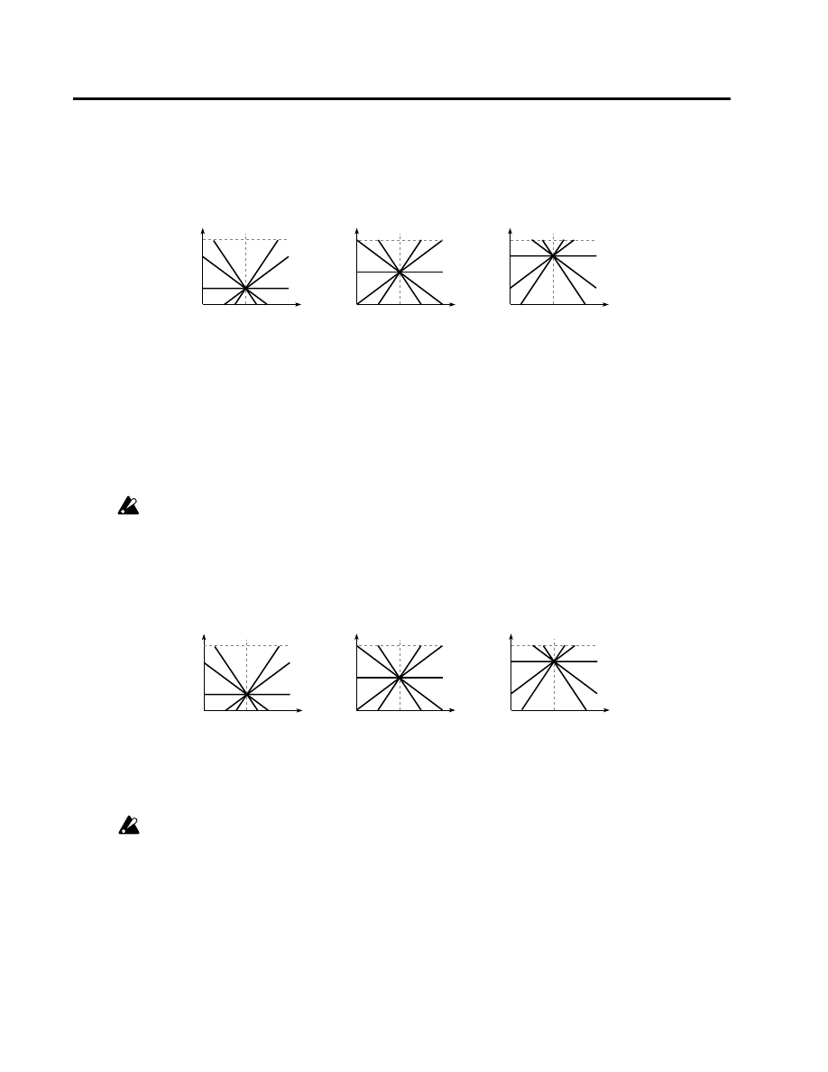
KTr (Damp Keyboard Track)
[–99…+99]
Specifies how the Damp amount will be affected by the keyboard location.
With positive (+) settings, the Damp value will increase as you play notes above C4. With negative (–) settings, the Damp
will decrease as you play notes above C4.
AMS (Alternate Modulation Source)
[OFF…MIDI (CC#83)]
Selects a modulation source (☞page 64 of this manual) that will control “Damp.”
Intensity (Damp AMS Intensity)
[–99…+99]
Specifies the depth and direction of the effect that “AMS” will have.
Decay
[0…99]
Specifies the decay time over which the sound will decay if you continue pressing a note. Higher settings of
this value
will produce a longer decay time.
Depending on the settings of “4-2: Amp EG”, the setting you make here may not have audible results. If you
raise the EG break level and sustain level, it will be easier to hear the result of this setting.
KTr (Decay Keyboard Track)
[–99…+99]
Specifies how the Decay amount will be affected by the keyboard location.
With positive (+) settings, the decay will become faster as you play notes above C4. With negative (–) settings, it will become
slower.
Release
[0…99]
Specifies the length of time over which the sound will decay after you release the note. Higher settings of this
value
will produce a longer release time.
Depending on the settings of “4-2: Amp EG”, the setting you make here may not have audible results. You
may need to raise the EG release level, it will be easier to hear the result of this setting.
2:1 OSC 1 (12: Plucked String Model)
when Damp=50
when Damp=75
when Damp=25
C-1
C4
C9
99
0
50
C-1
C4
C9
99
0
75
C-1
C4
C9
99
0
25
+99 +50
0
-99
-50
+99 +50
0
-50
-99
+99
+50
-50
-99
0
Damp
Damp
Damp
when Decay=50
when Decay=75
when Decay=25
C-1
C4
C9
99
0
50
C-1
C4
C9
99
0
75
C-1
C4
C9
99
0
25
+99 +50
0
-99
-50
+99 +50
0
-50
-99
+99
+50
-50
-99
0
Decay
Decay
Decay

2:1 OSC 1 (12: Plucked String Model)
Parameters
Prog.
Edit
P2
Dispersion
[0…99]
Specifies the inharmonicity of the higher partials relative to the fundamental. With a value of 0, the partials will
be located at integer (whole number) multiples of the fundamental. As this value is increased, the partials will
move further away from integer multiple locations. In general, thin and flexible strings can be simulated by a
low “Dispersion” value, and thick and stiff strings can be simulated by a high “Dispersion” value.
If this value is raised excessively, the pitch may become unstable.
AMS (Alternate Modulation Source)
[OFF…MIDI (CC#83)]
Selects a modulation source (☞page 64 of this manual) that will control “Dispersion.”
Intensity (Dispersion AMS Intensity)
[–99…+99]
Specifies the depth and direction of the effect of “AMS.”
2–1d: Harmonics
Position
[0…99]
Specifies the location at which the string will be pressed to play harmonics.
Control
[OFF…MIDI (CC#83)]
Selects a modulation source (☞page 64 of this manual) that will control the harmonics effect.
Intensity (Harmonics Control Intensity)
[–99…+99]
Specifies the depth and direction of the control that “AMS” will have on the harmonics effect.
When making the Position setting, you must assign Control to a controller other than OFF, and raise the
Intensity value. The decay time of the harmonics effect will differ depending on the keyboard location that
you play.
2–1e: Pickup
Pickup
If this is checked, the sound will be passed through a simulated pickup. If this is not checked, the sound will
remain unchanged.
Position, AMS, and Intensity can be set when Pickup has been checked.
Position
[0…99]
Adjusts the change in tone that results from differences in pickup location.
AMS (Alternate Modulation Source)
[OFF…MIDI (CC#83)]
Selects a modulation source (☞p64) that will control “Pickup.”
Intensity (Pickup Position AMS Intensity)
[–99…+99]
Specifies the depth and direction of the effect of “AMS.”
2–1f: Low EQ
Frequency
[0…49]
Specifies the cutoff frequency of the Low EQ.
Gain
[–18…+18]
Specifies the gain of the Low EQ.
Low Boost
[0…99]
Specifies how the low frequency range will be emphasized. Raising this value will cause the low frequency
range to be emphasized more strongly.
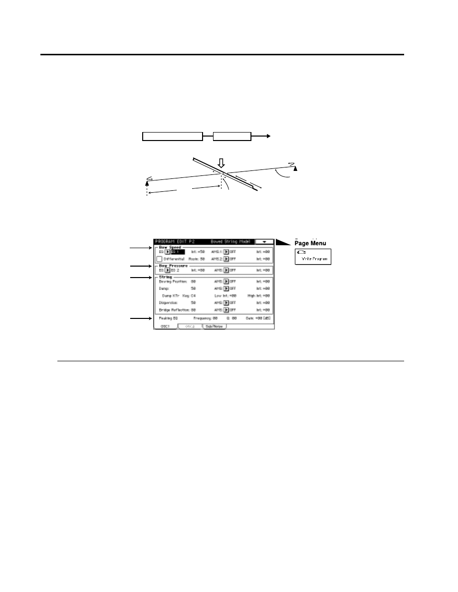
13: Bowed String Model
This oscillator is a physical model which simulates the sound of a bowed string instrument such as a
violin or cello. By controlling the bowing speed and the bowing pressure, you can create performance
expressions that are very close to those of an actual bowed string instrument.
2–1a: Bowing Speed
EG
[EG 1…EG 4, Amp EG]
Selects the EG which will control bowing speed (the speed at which the bow moves across the string).
Int. (Speed Modulation EG Intensity)
[–99…+99]
Specifies the depth and direction of the effect of “EG” With negative (–) settings, the direction of the bow speed
will be inverted.
AMS.1 (Alternate Modulation Source 1)
[OFF…MIDI (CC#83)]
Selects a modulation source 1 (☞page 64 of this manual) that will control bowing speed.
Instead of using an EG to modify the bowing speed, you can use the Ribbon Controller or Joy Stick to simulate bowing
without using an EG.
Int. (Speed AMS.1 Intensity)
[–99…+99]
Specifies the depth and direction of the effect of “AMS.1.”
AMS.2 (Alternate Modulation Source 2)
[OFF…MIDI (CC#83)]
Selects a modulation source 2 (☞page 64 of this manual) that will control bowing speed.
Int. (Speed AMS.2 Intensity)
[–99…+99]
Specifies the depth and direction of the effect of “AMS.2.”
2:1 OSC 1 (13: Bowed String Model)
Parameters related to the string
String Damp
Dispersion
String vibration
String
Bow
Position
Bow Speed
Pressure
Bridge Reflection
Bridge Reflection
Bowed String Model
Bowed String Model
Peaking EQ
2–1a
2–1b
2–1c
2–1d

2:1 OSC 1 (13: Bowed String Model)
Parameters
Prog.
Edit
P2
Differential
If this is not checked, the value produced by EG, AMS.1 and AMS.2 will be used as the bowing speed. If you wish
to use EG to control the bowing speed, leave this item un-checked.
If this is checked, the rate of change of EG, AMS.1 and AMS.2 will be used as the bowing speed.
• Using the ribbon controller to control bowing speed
As an example, we will assume that you have set AMS.1 to Ribbon (X). In order to control bowing speed using
the ribbon controller alone, raise the Int. (Speed AMS.1 Intensity) value, and set Int. (Speed Modulation EG
Intensity) to 0. Check Differential.
When you are pressing the ribbon controller, the bowing speed will be zero, so there will be no sound. As you
slide your finger toward the right over the ribbon controller, the speed at which your finger moves will be the
bowing speed, and sound will be produced. As you slide your finger to left and right, the bowing speed will
change from positive →zero→ negative→ zero→positive, allowing you to produce performance expressions
that are very similar to those of actually moving a bow back and forth.
Rosin
[0…99]
Specifies the coefficient of static friction between the bow and the string. (This corresponds to the amount of
rosin on the bow.)
Higher values will increase the friction between the bow and string. When this value is in the region of 0, it will
be difficult for playing strength to be transmitted to the string.
2–1b: Bow Pressure
EG
[EG 1…EG 4, Amp EG]
Selects the EG which will control the pressure of the bow on the string (bow pressure).
Int. (Press Modulation EG)
[–99…+99]
Specifies the depth and direction of the effect that the “EG” will have on bow pressure. If this value is low, the
bow will rest lightly on the string.
AMS (Alternate Modulation Source)
[OFF…MIDI (CC#83)]
Selects a modulation source (☞page 64 of this manual) that will control bow pressure.
Int.(Press AMS Intensity)
[–99…+99]
Specifies the depth of the effect produced by “AMS.”
2–1c: String
Bowing Position
[0…99]
Specifies the location at which the bow contacts the string. A setting of 0 is the end of the string, 50 is near the
middle, and 99 is at the other end.
AMS (Alternate Modulation Source)
[OFF…MIDI (CC#83)]
Selects a modulation source (☞page 64 of this manual) that will control “Bowing Position.”
Changing the location at which the string is bowed will also change the overtone structure.
Int. (Bowing Position AMS Intensity)
[–99…+99]
Specifies the depth and direction of the effect of “AMS.”
Damp
[0…99]
Specifies how the high frequency components will be attenuated by the characteristics of the string and by the
way in which the string is pressed onto the fingerboard of the violin or cello.
As this value is increased, the high frequency components of the wave transmitted along the string will be
attenuated more greatly, producing a darker sound. In general, you should use higher values to simulate
instruments which have flexible strings or unfretted instruments, and lower values to simulate instruments
with stiff strings or fretted instruments.
AMS (Alternate Modulation Source)
[OFF…MIDI (CC#83)]
Selects a modulation source (☞page 64 of this manual) that will control “Damp.”
Int. (Damp AMS Intensity)
[–99…+99]
Specifies the depth and direction of the effect of “Damping Mod.Source.”

Damp KTr Key
[C–1…G9]
Specifies the key above and below which keyboard tracking will begin to apply to the “Damp” effect.
Low Int
[–99…+99]
Specifies the depth and direction in which the “Damp” amount will change for notes below the “Damp KTr
Key.” Positive (+) settings will cause “Damp” to increase for notes below the “Damp KTr Key.” Negative (–)
settings will cause “Damp” to decrease for notes below the “Damp KTr Key.”
High Int
[–99…+99]
Specifies the depth and direction in which the “Damp” amount will change for notes above the “Damp KTr
Key.” Positive (+) settings will cause “Damp” to increase for notes above the “Damp KTr Key.” Negative (–)
settings will cause “Damping” to decrease for notes above the “Damping KTr Key.”
Dispersion
[0…99]
Specifies the inharmonicity of the higher partials relative to the fundamental. With a value of 0, the partials will
be located at integer (whole number)x multiples of the fundamental. As this value is increased, the partials will
move further away from integer multiple locations. In general, thin and flexible strings can be simulated by a
low “Dispersion” value, and thick and stiff strings can be simulated by a high “Dispersion” value.
If this value is raised excessively, the pitch may become unstable.
AMS (Alternate Modulation Source)
[OFF…MIDI (CC#83)]
Selects a modulation source (☞page 64 of this manual) that will control “Dispersion.”
Intensity (Dispersion AMS Intensity)
[–99…+99]
Specifies the depth and direction of the effect of “AMS.”
Bridge Reflection
[0…99]
Specifies the amount of the wave that will be reflected at the end of the string. Higher values will make the
notes sound more easily. With a setting of 0 there will be no reflection at all.
AMS (Alternate Modulation Source)
[OFF…MIDI (CC#83)]
Selects a modulation source (☞page 64 of this manual) that will control “Bridge Reflection.”
Int. (Bridge Reflection AMS Intensity)
[–99…+99]
Specifies the depth and direction of the effect of “AMS.”
2–1d: Peaking EQ
Frequency
[0…49]
Specifies the center frequency at which the peaking EQ will boost (attenuate) the sound.
Q
[0…29]
Specifies the width of the region that will be boosted (attenuated) by the peaking EQ. With a setting of 0, a wide
region will be affected. With a setting of 29, only a narrow region close to the center frequency will be boosted
(attenuated).
Gain
[–18…+18]
Specifies the gain by which the peaking EQ will boost or attenuate.
2–2: OSC 2
OSC2 parameters have the same structure as OSC1 parameters. Refer to “2-1: OSC 1.”
2:1 OSC 1 (13: Bowed String Model), 2-2: OSC 2
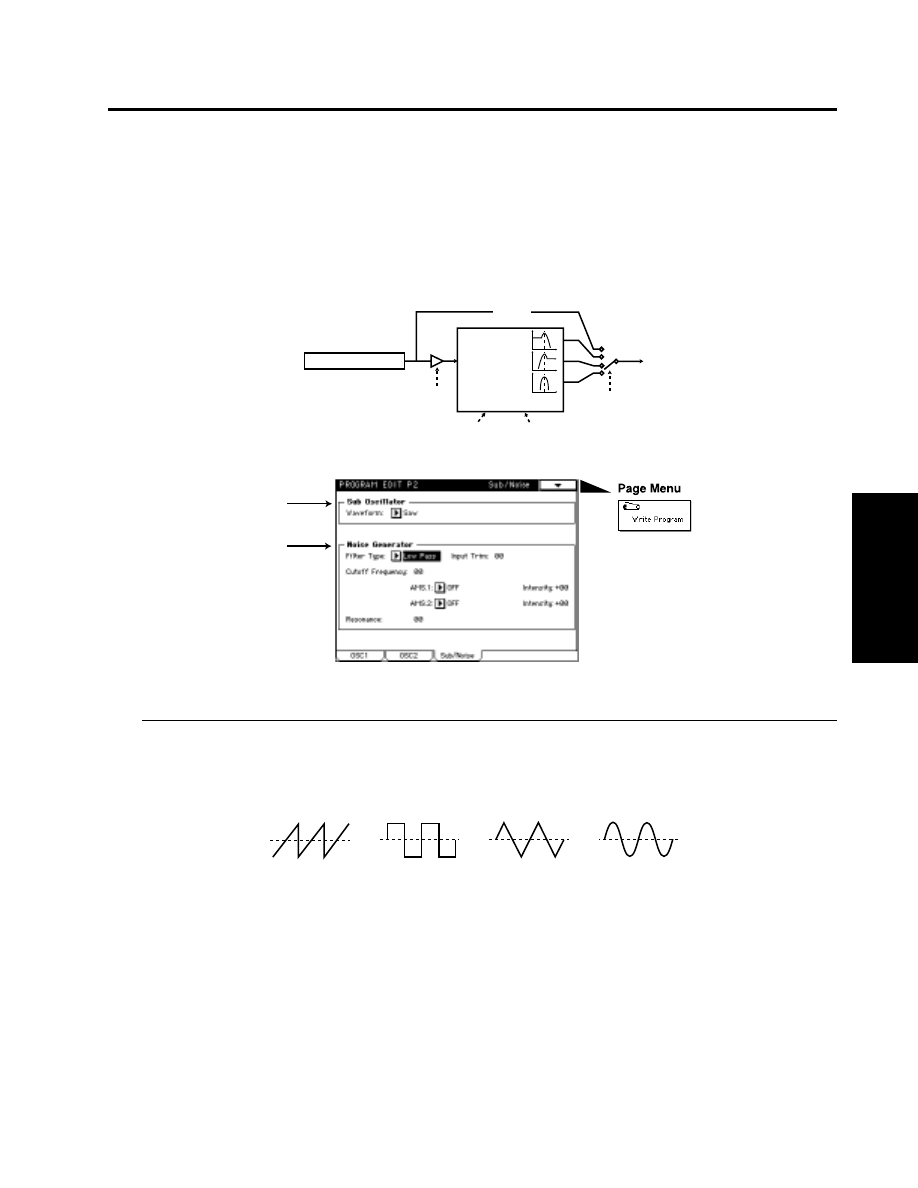
2–3: Sub/Noise
Here, you can make settings for the sub-oscillator and the noise generator.
The sub oscillator lets you select one of four basic waveforms. In the mixer section, the signal from
the sub oscillator is mixed with the signals of oscillators 1 and 2.
The noise generator produces white noise. The noise signal that is generated passes through a dedicated
filter, and is mixed by the mixer section with the signals from the sub oscillator and oscillators 1 and
2.
2–3a: Sub Oscillator
Wave Form
[Saw, Square, Triangle, Sine]
Specifies the type of filter that will be applied to the output from the noise generator.
2-3: Sub/Noise
Parameters
Prog.
Edit
P2
Noise Generator
Cutoff Frequency
Resonance
Low Pass
High Pass
Band Pass
Thru
Filter Type
Input Trim
Noise Filter
2–3a
2–3b
Saw
Square
Triangle
Sine

2-3: Sub/Noise
2–3b: Noise Generator
Here, you can make various settings for the noise generator.
Filter Type
[Thru, Low Pass, High Pass, Band Pass]
Selects the type of filter that will be applied to the output of the noise generator.
When Thru is selected, the Input Trim, Frequency, AMS.1, Intensity (Cutoff Frequency AMS.1 Intensity), AMS.2,
Intensity (Cutoff Frequency AMS.2 Intensity), and Resonance settings will be unavailable.
Input Trim
[0…99]
Specifies the input level to the dedicated noise filter.
Cutoff Frequency
[0…99]
Specifies the cutoff frequency of the noise signal filter. For the characteristics of each filter type, refer to “3-
2b:Filter1” (☞page 47 of this manual).
AMS.1 (Alternate Modulation Source 1)
[OFF…MIDI (CC#83)]
Selects a modulation source 1 (☞page 64 of this manual) that will control the “Cutoff Frequency.”
Intensity (Cutoff Frequency AMS.1 Intensity)
[–99…+99]
Specifies the depth and direction of the effect of “AMS.1.”
AMS.2 (Alternate Modulation Source 2)
[OFF…MIDI (CC#83)]
Selects a modulation source 2 (☞page 64 of this manual) that will control the “Cutoff Frequency.”
Intensity (Cutoff Frequency AMS.2 Intensity)
[–99…+99]
Specifies the depth and direction of the effect of “AMS.2.”
Resonance
[0…99]
This boosts the frequency region specified by the “Cutoff Frequency” to add character to the sound. Since the
filter characteristics differ from the filter type of the “3-2b: Filter 1 ,” “3-4b: Filter 2” the resulting effect will be
different even if “Type,” “Cutoff Frequency” and “Resonance” settings are identical.
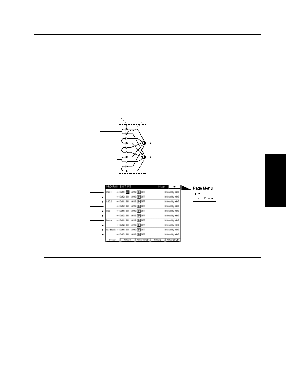
3-1: Mixer
Parameters
Prog.
Edit
P3
Program Edit P3
Here, you can make settings for the mixer and filter.
For the way in which the mixer, filter and amp sections are connected, refer to “3-2a: Filter Routing.”
3–1: Mixer
The mixer allows you to set the levels at which the five signals (OSC 1, OSC 2, Noise Generator,
Feedback, Sub OSC) will be combined into the two mixer outputs. You can also select a modulation
source to control each level, and specify its intensity.
3–1a: OSC 1 ➝ Out 1
These parameters adjust the level at which the oscillator 1 signal is output from mixer output 1, and
specify a modulation source that will control this level.
Output Level
[00...99]
Specifies the signal level that will be output to mixer output 1.
AMS (Alternate Modulation Source)
[OFF…MIDI (CC#83)]
Selects a modulation source (☞page 64 of this manual) that will control “output level.”
Intensity (Level AMS Intensity)
[–99...+99]
Specifies the depth and direction of the effect of “AMS.”
With positive (+) settings, higher values of the modulation source will increase the “output level.” With negative
(–) settings
, lower values of the modulation source will increase the “output level.” If EG or LFO has been
selected as the “AMS”, positive (+) settings will cause the original phase of the EG or LFO to be used, and
negative (–) settings
will invert the phase.
OSC1
OSC2
Sub OSC
Noise Generator
Feed back
Mixer Out1
Mixer Out2
OSC1 Mixer Out1 Level
OSC1 Mixer Out2 Level
3–1a
3–1b
3–1c
3–1d
3–1e
3–1f
3–1g
3–1h
3–1i
3–1j

3–1b: OSC 1 ➝ Out 2
These parameters adjust the level at which the oscillator 1 signal is output from mixer output 2, and
specify a modulation source that will control this level.
Refer to the above explanation of “3-1a: OSC1 ➝ OUT1.”
3–1c: OSC 2 ➝ Out 1
These parameters adjust the level at which the oscillator 2 signal is output from mixer output 1, and
specify a modulation source that will control this level.
Refer to the above explanation of “3-1a: OSC1 ➝ OUT1.”
3–1d: OSC 2 ➝ Out 2
These parameters adjust the level at which the oscillator 2 signal is output from mixer output 2, and
specify a modulation source that will control this level.
Refer to the above explanation of ”3-1a: OSC1 ➝ OUT1.”
3–1e: Sub ➝ Out 1
These parameters adjust the level at which the sub oscillator signal output is output from mixer
output 1, and specify a modulation source that will control this level.
Refer to the above explanation of “3-1a: OSC1 ➝ OUT1.”
3–1f: Sub ➝ Out 2
These parameters adjust the level at which the sub oscillator signal output is output from mixer
output 2, and specify a modulation source that will control this level.
Refer to the above explanation of “3-1a: OSC1 ➝ OUT1.”
3–1g: Noise ➝ Out 1
These parameters adjust the level at which the output of the noise generator is output from mixer
output 1, and specify a modulation source that will control this level.
Refer to the above explanation of “3-1a: OSC1 ➝ OUT1.”
3–1h: Noise ➝ Out 2
These parameters adjust the level at which the output of the noise generator is output from mixer
output 2, and specify a modulation source that will control this level.
Refer to the above explanation of “3-1a: OSC1 ➝ OUT1.”
3–1i: Feedback ➝ Out 1
These parameters adjust the level at which the feedback from the amp section is output from mixer
output 1, and specify a modulation source that will control this level.
Refer to the above explanation of “3-1a: OSC1 ➝ OUT1.”
Raising the Feedback level excessively may cause the sound to distort.
3–1j: Feedback ➝ Out 2
These parameters adjust the level at which the feedback from the amp section is output from mixer
output 2, and specify a modulation source that will control this level.
Refer to the above explanation of “3-1a: OSC1 ➝ OUT1.”
Raising the Feedback level excessively may cause the sound to distort.
3-1: Mixer
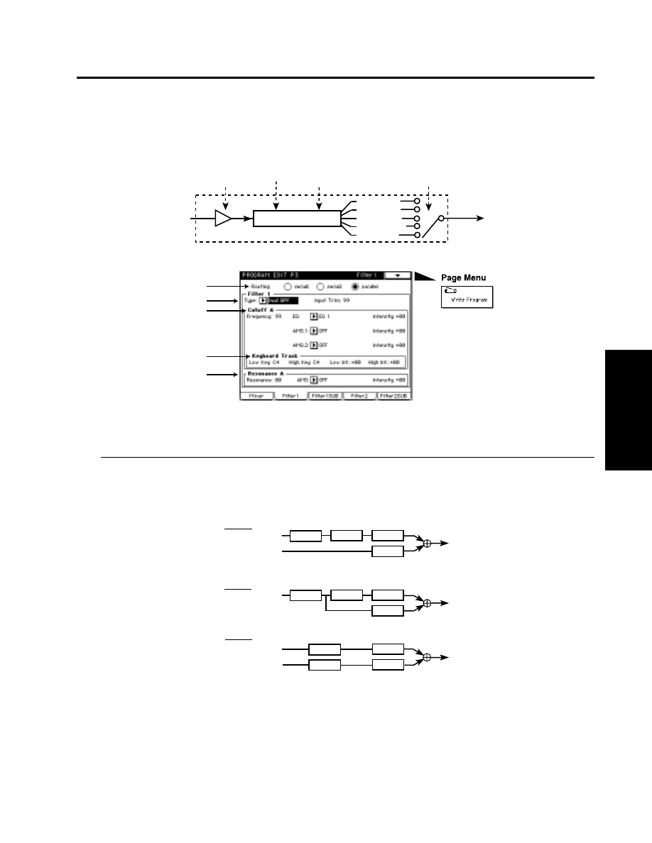
3-2: Filter 1
Parameters
Prog.
Edit
P3
3–2: Filter 1
Here, you can make settings for one of the two multi-mode filters. Each multi-mode filter can be set
to one of five filter types.
3–2a: Routing (Filter Routing)
[serial 1/serial 2/parallel]
Use the radio buttons to select the way in which filters 1 and 2 will be combined.
The connections from mixer output
→
filter
→
amp can be routed in the following three ways.
Multimode Filter
Low Pass
High Pass
Band Pass
Band Reject
Dual BPF
Filter Type
Input Trim
Cutoff Frequency
Resonance
3–2a
3–2b
3–2c
3–2d
3–2e
Serial1
Parallel
Mixer Output1
Mixer Output2
Filter1
Filter2
Amp1
Amp2
Mixer Output1
Mixer Output2
Filter1
Filter2
Amp1
Amp2
Mixer Output1
Mixer Output2
Filter1
Filter2
Amp1
Amp2
Serial2
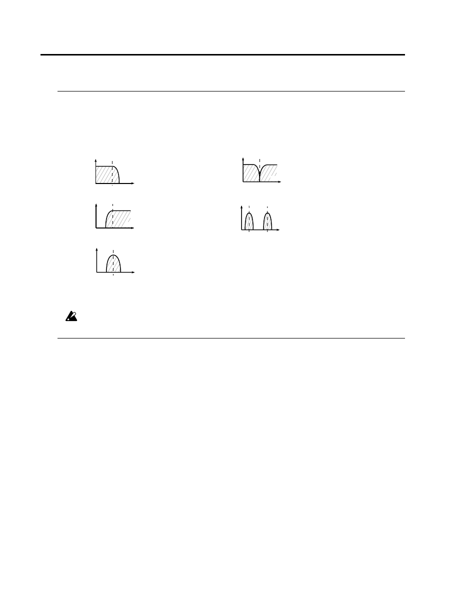
3–2b: Filter 1
Type
[Low Pass, High Pass, Band Pass, Band Reject, Dual BPF]
Selects the filter type.
When Dual BPF is selected, the “3-3: Filter 1 SUB” parameters can also be set. When you select Dual BPF, the “3-
2c: Cutoff” and “3-2e: Resonance” parameter names will change to Cutoff A and Resonance A respectively.
Input Trim
[0…99]
Specifies the level of the input to filter 1.
If this value is raised, the sound may become distorted if the resonance setting is high, etc.
3–2c: Cutoff/Cutoff A (Cutoff Frequency)
Frequency
[0…99]
Specifies the cutoff frequency of filter 1. As this value is increased, the cutoff frequency will rise.
Since the BPF and Dual BPF filter types use filters with differing characteristics, their actual cutoff frequency
may differ even if their settings are identical.
EG (Cutoff Frequency Modulation EG)
[EG1…EG4, Amp EG]
Selects the EG that will create time-varying change in the cutoff frequency of filter 1.
Intensity (Cutoff Frequency Mod. EG Intensity)
[–99…+99]
Specifies the depth and direction of the control that “EG (Cutoff Frequency Modulation EG)” will have on the
cutoff frequency. With positive (+) settings of this parameter, the tone will become brighter when the various EG
levels rise into the + area (the setting of the “Frequency” will be reached when the EG levels are at 0), and darker
when the EG levels fall into the – area. With negative (–) settings of this parameter, the tonal change will take
place in the opposite direction.
AMS.1 (Alternate Modulation Source 1)
[OFF…MIDI (CC#83)]
Selects a modulation source 1 (☞page 64 of this manual) that will control “Frequency.”
Intensity (Cutoff Frequency AMS.1 Intensity)
[–99…+99]
Specifies the depth and direction of the effect that “AMS.1” will have on the cutoff frequency.
AMS.2 (Alternate Modulation Source 2)
[OFF…MIDI (CC#83)]
Selects a modulation source 2 (☞page 64 of this manual) that will control “Frequency.”
Intensity (Cutoff Frequency AMS.2 Intensity)
[–99…+99]
Specifies the depth and direction of the effect that “AMS.2” will have on the cutoff frequency.
Filter Types and Cutoff Frequency
Low Pass Filter (LPF)
Dual Band Pass Filter (Dual BPF)
Cutoff
Frequency A
Cutoff
Frequency B
A low pass filter is the most
commonly-used type of filter, and
passes the range of frequencies that
lie below the cutoff frequency, and
cuts the high range. Cutting the higher
partials will cause a bright sound to
become darker (more mellow).
A high pass filter passes the range of
frequencies that lie above the cutoff
frequency, and cuts the low range.
This type of filter is used when you
wish to make the sound thinner.
However, raising the cutoff frequency
excessively will drastically reduce the
volume.
A band pass filter passes the range of
frequencies in the vicinity of the cutoff
frequency, and cuts the
ranges
above and below. This type of filter is
used when you wish to emphasize a
particular portion of the sound.
The dual band pass filter places
two band pass filters in parallel.
It allows you to simulate sounds
such as human voice and the
body resonances of a violin or
guitar.
Band Pass Filter (BPF)
High Pass Filter (HPF )
Cutoff
Frequency
A band reject filter cuts only the
range in the vicinity of the cutoff
frequency, and passes the rest
of the sound. This type of filter
gives a unique character to the
sound.
Band Reject Filter (BRF)
Cutoff Frequency
Cutoff Frequency
Cutoff Frequency
frequency
frequency
frequency
frequency
frequency
3-2: Filter 1
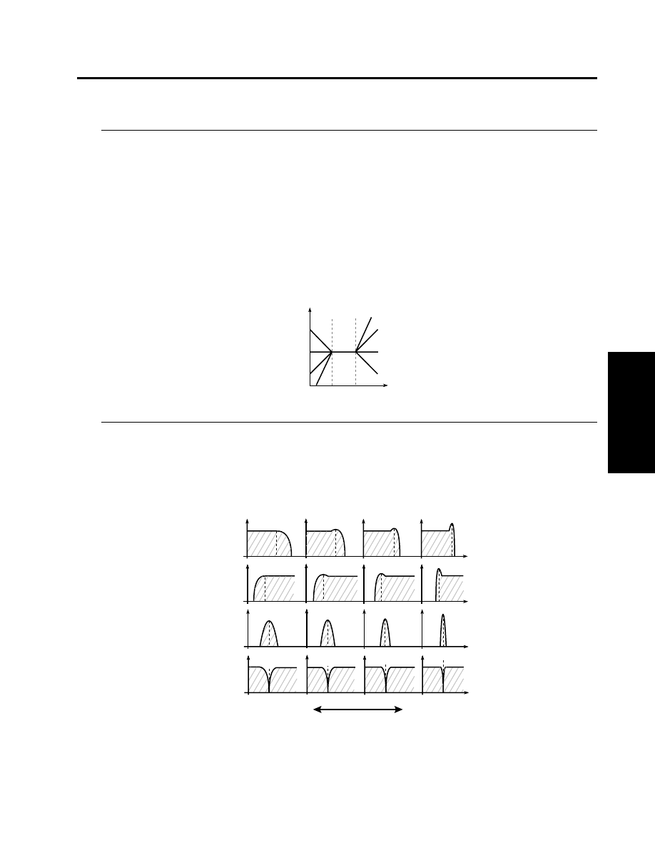
3–2d: Keyboard Track
Keyboard tracking settings specify how the cutoff frequency of filter 1 will be varied according to
keyboard position.
Low Key
[C-1…G9]
Specifies the key at which Lower keyboard tracking will begin.
High Key
[C-1…G9]
Specifies the key at which Higher keyboard tracking will begin.
Low Int.
[–99…+99]
Specifies the depth and direction of cutoff frequency change that will occur below the “Low Key.” With a
setting of –50, the change will match the change in pitch.
High Int.
[–99…+99]
Specifies the depth and direction of cutoff frequency change that will occur above the “High Key.” With a
setting of +50, the change will match the change in pitch.
3–2e: Resonance/Resonance A
Resonance
[0…99]
This setting emphasizes the overtones in the region of the “Frequency” to add character to the sound. Higher
values
will produce a stronger effect. With high settings of resonance, the output signal of the filter may distort.
If this occurs, reduce the “Input Trim” setting.
With the Dual BPF filter type, the overtones in the vicinity of each cutoff frequency will be affected in the same
way as by a BPF.
AMS (Alternate Modulation Source)
[OFF…MIDI (CC#83)]
Selects a modulation source (☞page 64 of this manual) that will control the amount of resonance.
Intensity (Resonance AMS Intensity)
[–99…+99]
Specifies the depth and direction of the effect that “AMS” will have on the amount of resonance.
3-2: Filter 1
Parameters
Prog.
Edit
P3
Cutoff
frequency
C-1
C4
C9
Int=-50
Int= 0
Int> 0
Low
Key
High
Key
Int=0
Int=+50
Int=+99
Int<0
Int=-99
Low resonance value
High resonance value
The effect of resonance
Low Pass
High Pass
Band Pass
Band Reject
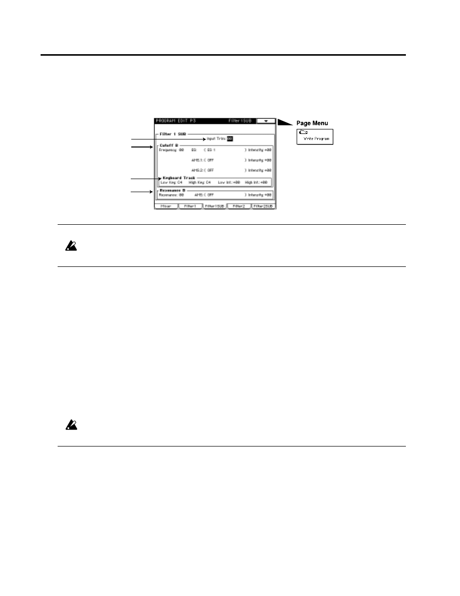
3–3: Filter 1SUB
If the “3-2b: Filter 1” Type parameter was set to Dual BPF, you can make settings for the “3-3: Filter
1 SUB” parameters.
3–3a: Input Trim
[0…99]
Specifies the level of the input to filter 1.
If this value is raised, the sound may become distorted if the resonance setting is high, etc.
3–3b: Cutoff B (Cutoff Frequency B)
Frequency
[0…99]
Specifies the cutoff frequency of filter 1. As this value is increased, the cutoff frequency will rise.
Since the BPF and Dual BPF filter types use filters with differing characteristics, their actual cutoff frequency
may differ even if their settings are identical.
EG Intensity (Cutoff Frequency Modulation EG Intensity)
[–99…+99]
Specifies the depth and direction of the effect that the EG specified by “3-2: Filter 1” will have on the cutoff
frequency. With positive (+) settings of this parameter, positive (+) EG levels will make the sound brighter
relative to the value specified by Frequency, and negative (–) EG levels will make the sound darker. (When an
EG level is 0, the value specified by Frequency will be used unchanged.) With negative (–) settings of this
parameter, the change will take place in the opposite direction of positive (+) settings.
AMS.1 Intensity
[–99…+99]
Specifies the depth and direction of the effect that the AMS.1 specified in “3-2c: Cutoff” will have on the cutoff
frequency.
AMS.2 Intensity
[–99…+99]
Specifies the depth and direction of the effect that the AMS.2 specified in “3-2c: Cutoff” will have on the cutoff
frequency.
It is not possible to change EG, AMS.1 or AMS.2 in the Filter 1 SUB page.
3–3c: Keyboard Track
Keyboard tracking settings specify how the cutoff frequency of filter 1 will be varied according to keyboard
position.
Low Key
[C-1…G9]
Specifies the key at which Lower keyboard tracking will begin.
High Key
[C-1…G9]
Specifies the key at which Higher keyboard tracking will begin.
3-3: Filter 1 SUB
3–3a
3–3b
3–3c
3–3d

Low Int.
[–99…+99]
Specifies the depth and direction of cutoff frequency change that will occur below the “Low Key.” With a
setting of –50, the change will match the change in pitch.
High Int.
[–99…+99]
Specifies the depth and direction of cutoff frequency change that will occur above the “High Key.” With a
setting of +50, the change will match the change in pitch.
3–3d: Resonance B
Resonance
[0…99]
This setting emphasizes the overtones in the region of the “Frequency” to add character to the sound. Higher
values will produce a stronger effect. With high settings of resonance, the output signal of the filter may distort.
If this occurs, reduce the “Input Trim” setting.
With the Dual BPF filter type, the overtones in the vicinity of each cutoff frequency will be affected in the same
way as by a BPF.
AMS Intensity
[–99…+99]
Specifies the depth and direction of the effect that the AMS specified in “3-2e: Resonance” will have on the
resonance.
3-3: Filter 1 SUB
Parameters
Prog.
Edit
P3
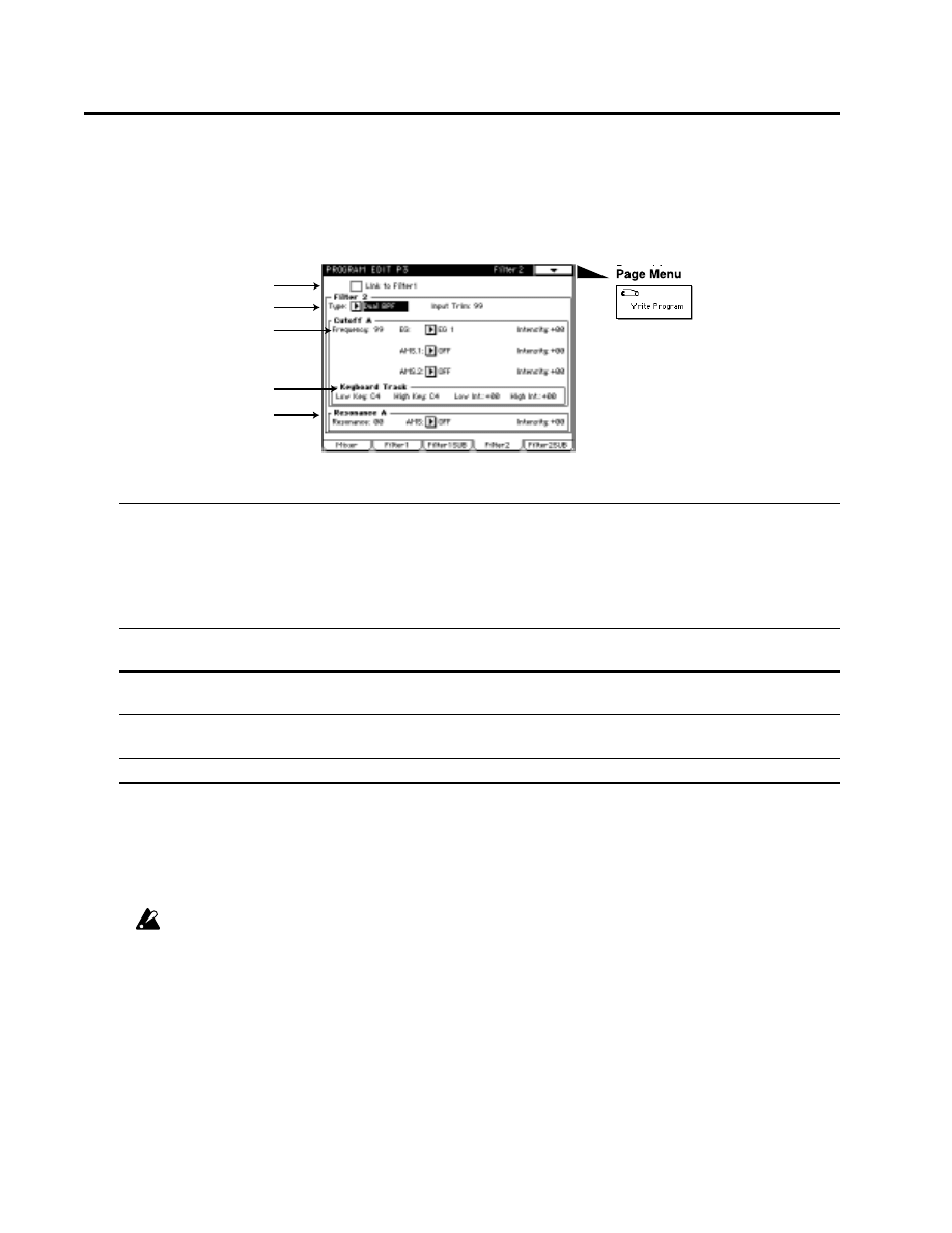
3–4: Filter 2
Here, you can make settings for one of the two multi-mode filters. Each multi-mode filter can be set
to one of five filter types.
3–4a: Link to Filter 1
If this is checked, Filter 2 will be linked to Filter 1, and the following settings will be the same as the
settings of Filter 1.
If this is not checked, the following parameters can be set for Filter 2.
For details on these parameters, refer to “3-2: Filter 1.”
3–4b: Filter 2
3–4c: Cutoff/Cutoff A (Cutoff Frequency)
3–4d: Keyboard Track
3–4e: Resonance/Resonance A
3–5: Filter 2 SUB
When “3-4b: Filter 2” Type parameter is set to Dual BPF, you will be able to set various parameters
for “3-5: Filter 2 SUB.”
For details on these parameters, refer to “3-3: Filter 1 SUB.”
If “3-4a: Link to Filter 1” is checked, it is not possible to make “3-5: Filter 2 SUB” settings.
3-4: Filter 2, 3-5: Filter 2 SUB
3–4a
3–4b
3–4c
3–4d
3–4e
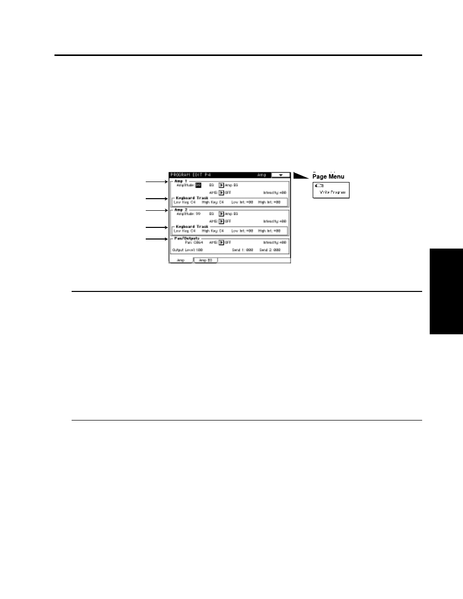
Program Edit P4
Here, you can make volume-related settings.
There are two independent amps, and the signals which are input to each amp are determined by the
setting of “3-2a: Routing” (☞page 47 of this manual).
4–1: Amp
4–1a: Amp 1
Amplitude
[0…99]
Specifies the volume level of amp 1. The input signal to amp 1 is determined by the “3-2a:Routing” setting
EG (Amplitude Modulation EG)
[EG1…EG4, Amp EG]
Selects the EG that will create time-variant change in the volume level of amp 1. For the settings of each EG,
refer to “Program Edit P5.”
AMS (Alternate Modulation Source)
[OFF…MIDI (CC#83)]
Selects a modulation source (☞page 64 of this manual) that will control the volume level of amp 1.
Intensity (Amplitude AMS Intensity)
[–99…+99]
Specifies the depth and direction of the effect of “AMS” on the volume level.
4–1b: Keyboard Track (Amplitude 1 Keyboard Track)
Low Key
[C-1…G9]
Specifies the key at which Lower keyboard tracking will begin.
High Key
[C-1…G9]
Specifies the key at which Higher keyboard tracking will begin.
Low Int.
[–99…+99]
Specifies the way in which keyboard tracking will affect the volume of notes below the Low Key.
4-1: Amp
Parameters
Prog.
Edit
P4
4–1a
4–1b
4–1c
4–1d
4–1e
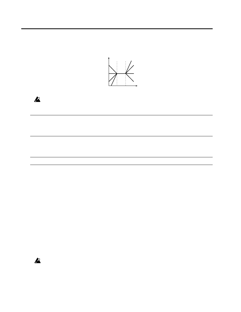
High Int.
[–99…+99]
Specifies the way in which keyboard tracking will affect the volume of notes below the High Key.
If Low Int. or High Int. are set to positive (+) settings, you will need to lower the “4-1a: Amp 1” Amplitude
value.
4–1c: Amp 2
Here you can adjust the settings for Amp 2. These parameters have the same structure as the “4-1a:
Amp 1” parameters.
4–1d: Keyboard Track (Amplitude 2 Keyboard Track)
Here you can adjust keyboard tracking settings for Amp 2. These parameters have the same structure
as the “4-1b: Keyboard Track” parameters.
4–1e: Pan/Outputs
Pan
[OFF, L000…C064…R127]
This sets the panning for input to the insert effect.
If you are not using an insert effect, this sets the panning to output jacks 1/L/MONO and 2/R.
With a setting of OFF, the sound will not be output to 1/L/MONO and 2/R.
L
is left, C is center, and R is right.
AMS (Alternate Modulation Source)
[OFF…MIDI (CC#83)]
Selects the modulation source (☞page 36 of this manual) that will move the panning of amp 1 relative to the
Pan setting.
Intensity (Panpot AMS Intensity)
[–99…+99]
Specifies the depth and direction of the effect of “AMS” on the panning.
Output Level
[0…127]
Specifies the output level following the amp.
Send 1
[0…127]
Send 2
[0…127]
Here, you can specify the input levels to the master effects when insertion effects are not used.
If you are using insertion effects, the input levels to the master effects are specified by the “7-1b: Pan/Width/
Send 1, 2” parameters Send 1 and 2 (☞page 41 in Parameter Guide).
In all modes, you must use an insertion effect when using bank M programs. If you do not use an insertion
effect, the output level will be decreased.
4-1: Amp
Volume level
C-1
C4
C9
Int=-50
Int= 0
Int> 0
Low
Key
High
Key
Int=0
Int=+50
Int=+99
Int<0
Int=-99
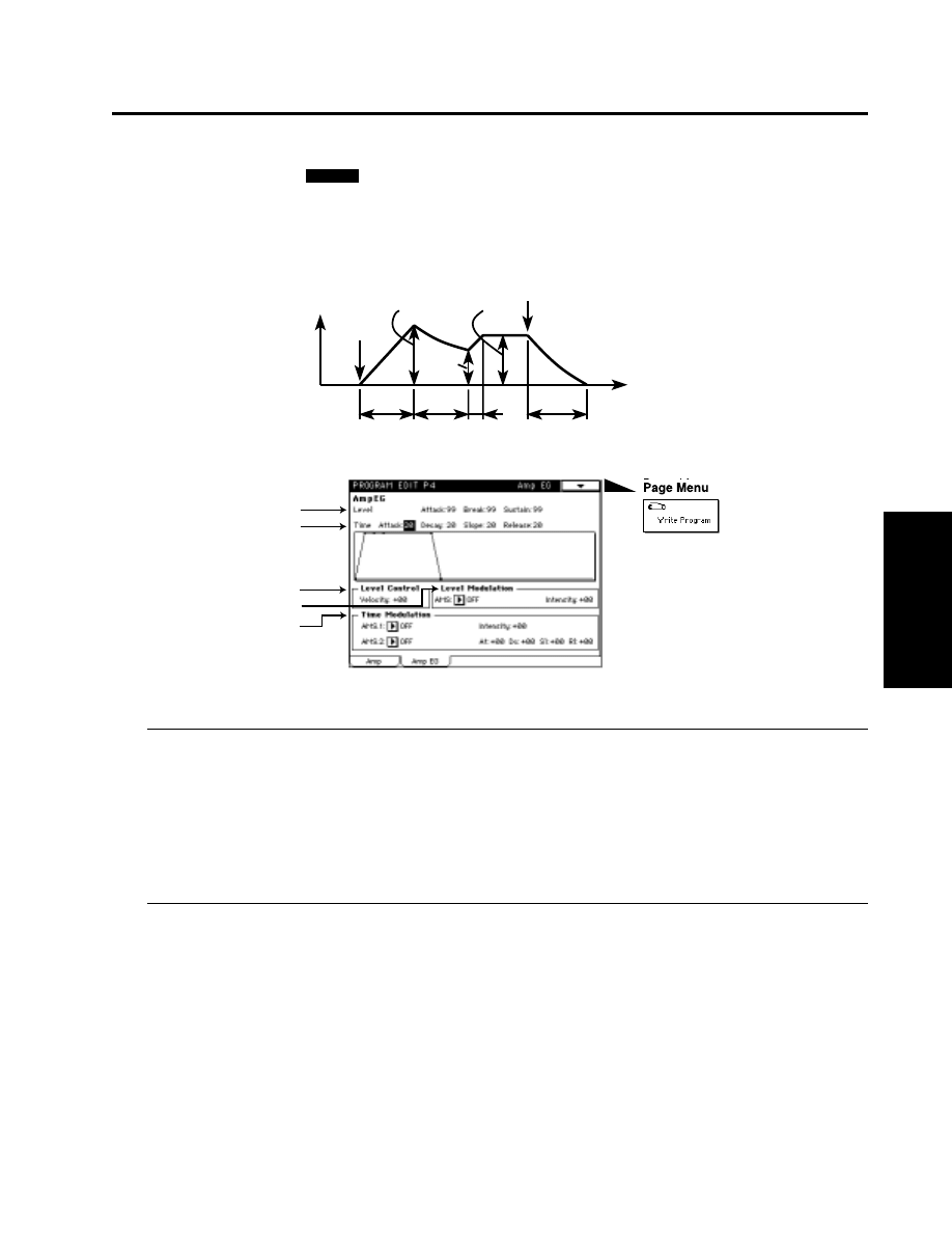
4-2: Amp EG
Here, you can make settings for the Amp EG. The Amp EG lets you specify how the sound will
change over time. Since the Amp EG can also be used as a general-purpose controller, it can create
time-variant change in parameters other than volume.
4–2a: Level (Amp EG Level)
[0…99]
Attack (Attack Level)
[0…99]
Specifies the volume that will be reached after the Attack Time has elapsed.
Break (Break Level)
[0…99]
Specifies the volume level that will be reached after the Decay Time has elapsed.
Sustain (Sustain Level)
[0…99]
Specifies the volume level that will be reached after the Slope Time has elapsed.
4–2b: Time (Amp EG Time)
Attack (Attack Time)
[0…99]
Specifies the time from note-on (when a note is played) until the volume reaches the attack level. With a value
of 0, the volume will change instantly. With a value of 99, the volume will change slowly.
Decay (Decay Time)
[0…99]
Specifies the time from when the attack time ends until the break level is reached.
Slope (Slope Time)
[0…99]
Specifies the time from when the decay time ends until the sustain level is reached.
Release (Release Time)
[0…99]
Specifies the time from note-off (when a note is released) until the volume falls to zero.
4-2: Amp EG
Parameters
Prog.
Edit
P4
AMSource
Note-off
Attack level
Sustain level
Note-on
Attack
time
Decay
time
Slope
time
Release
time
Time
Break
level
Volume
Time-variant change in volume created by the amp EG
4–2a
4–2b
4–2c
4–2d
4–2e
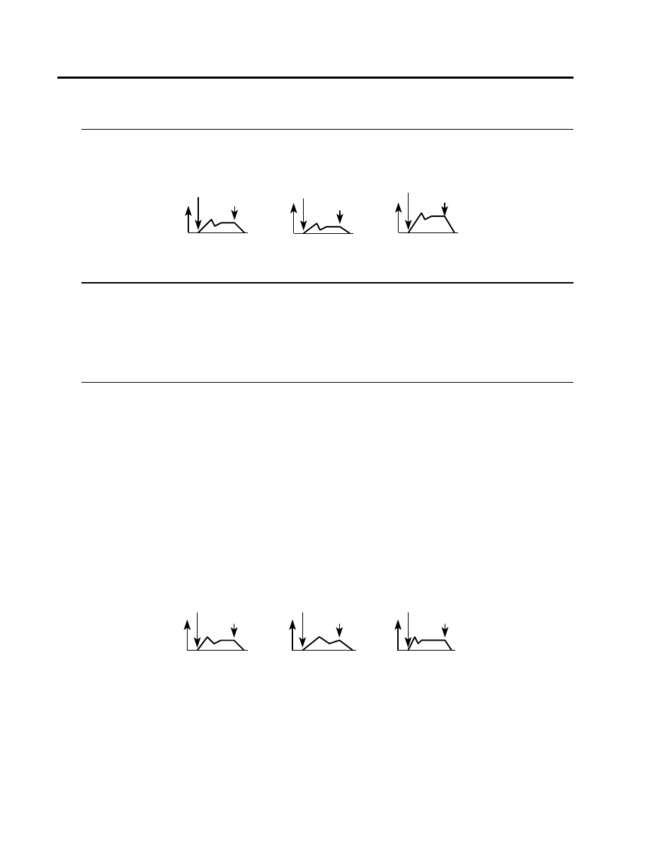
4–2c: Level Control
Velocity
[–99…+99]
Specifies the depth and direction of the effect that velocity will have on the level of the amp EG.
4–2d: Level Modulation
AMS (Alternate Modulation Source)
[OFF…MIDI (CC#83)]
Selects a modulation source (☞page 64 of this manual) that will control the level of the Amp EG.
Intensity (EG Level AMS Intensity)
[–99…+99]
Specifies the depth and direction of the effect that “AMS” will have on the level of the Amp EG.
4–2e: Time Modulation
AMS.1 (Alternate Modulation Source 1)
[OFF…MIDI (CC#83)]
Selects a modulation source 1 (☞page 64 of this manual) that will control the Amp EG times.
Intensity (EG Time AMS.1 Intensity)
[–99…+99]
Specifies the depth and direction of the effect that “AMS.1” will have on the Amp EG times.
AMS.2 (Alternate Modulation Source 2)
[OFF…MIDI (CC#83)]
Selects a modulation source 2 (☞page 64 of this manual) that will control the Amp EG times.
At (Attack Time AMS.2 Intensity)
[–99…+99]
Dc (Decay Time AMS.2 Intensity)
[–99…+99]
Sl (Slope Time AMS.2 Intensity)
[–99…+99]
Rl (Release Time AMS.2 Intensity)
[–99…+99]
Specifies the depth and direction of the effect that “AMS.2” will have on each EG time.
4-2: Amp EG
When " Velocity" is set to a positive (+) value
Note-on
Note-off
Note-on
Note-off
Note-on
Note-off
Settings of the Amp EG
Softly played notes
Strongly played notes
When the various EG times are set to negative (–) values
Note-on
Note-off
Note-on
Note-off
Note-on
Note-off
Settings of the Amp EG
Softly played notes
Strongly played notes
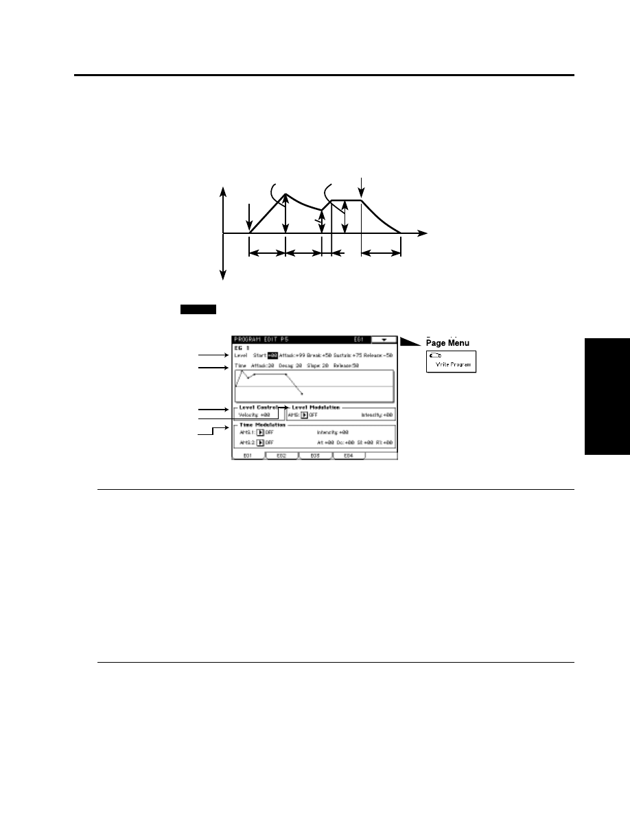
Program Edit P5
This section provides four general purpose EGs (envelope generators). The four EGs can be used as
modulation sources for the parameters of other sections to create time-variant change in the sound.
5–1: EG 1
5–1a: Level
Start (Start Level)
[–99…+99]
Specifies the value at the time of note-on.
Attack (Attack Level)
[–99…+99]
Specifies the value that will be reached after the Attack Time has elapsed.
Break (Break Level)
[–99…+99]
Specifies the value that will be reached after the Decay Time has elapsed.
Sustain (Sustain Level)
[–99…+99]
Specifies the value that will be reached after the Slope Time has elapsed.
Release (Release Level)
[–99…+99]
Specifies the value that will be reached after the Release Time has elapsed.
5–1b: Time (Amp EG Time)
Attack (Attack Time)
[0…99]
Specifies the time from note-on (when a note is played) until the value reaches the attack level. With a value of
0
, the value will change instantly. With a value of 99, the value will change slowly.
5-1: EG 1
Parameters
Prog.
Edit
P5
Note-off
Attack level
Sustain level
Note-on
Attack
time
Decay
time
Slope
time
Release
time
Time
Break
level
0
-99
+99
5–1a
5–1b
5–1c
5–1d
5–1e
AMSource
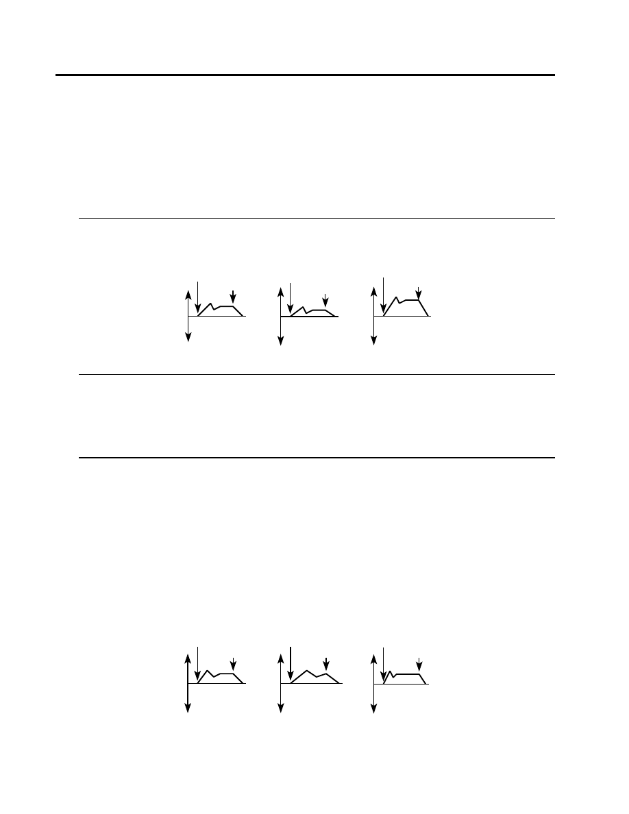
Decay (Decay Time)
[0…99]
Specifies the time from when the attack time ends until the Break Level is reached.
Slope (Slope Time)
[0…99]
Specifies the time from when the decay time ends until the Sustain Level is reached.
Release (Slope Time)
[0…99]
Specifies the time from note-off (when a note is released) until the Release Level is reached.
5–1c: Level Control
Velocity
[–99…+99]
Specifies the depth and direction of the effect that velocity will have on the EG levels.
5–1d:Level Modulation
AMS (Alternate Modulation Source)
[OFF…MIDI (CC#83)]
Selects a modulation source (☞page 64 of this manual) that will control the level of EG1.
Intensity (EG Level AMS Intensity)
[–99…+99]
Specifies the depth and direction of the effect that “AMS” will have on the EG levels.
5–1e: Time Modulation
AMS.1 (Alternate Modulation Source 1)
[OFF…MIDI (CC#83)]
Selects a modulation source 1 (☞page 64 of this manual) that will control the EG1 times.
Intensity (EG Time AMS.1 Intensity)
[–99…+99]
Specifies the depth and direction of the effect that “AMS.1” will have on the EG times.
AMS.2 (Alternate Modulation Source 2)
[OFF…MIDI (CC#83)]
Selects a modulation source 2 (☞page 64 of this manual) that will control the EG1 times.
At (Attack Time AMS.2 Intensity)
[–99…+99]
Dc (Decay Time AMS.2 Intensity)
[–99…+99]
Sl (Slope Time AMS.2 Intensity)
[–99…+99]
Rl (Release Time AMS.2 Intensity)
[–99…+99]
Specifies the depth and direction of the effect that “AMS.2” will have on each EG time.
5-1: EG 1
When "Velocity" is set to a positive (+) value
Note-on
Note-off
Note-on
Note-off
Note-on
Note-off
Settings of EG1
Softly played notes
Strongly played notes
When the various EG times are set to negative (–) values
Note-on
Note-off
Note-on
Note-off
Note-on
Note-off
Settings of EG1
Softly played notes
Strongly played notes

5-2: EG 2, 5-3: EG 3, 5-4: EG 4
Parameters
Prog.
Edit
P5
5–2: EG 2
5–3: EG 3
5–4: EG 4
EG 2, EG 3 and EG 4 have the same parameters as EG 1. Refer to “5-1: EG 1.”
AMSource
AMSource
AMSource
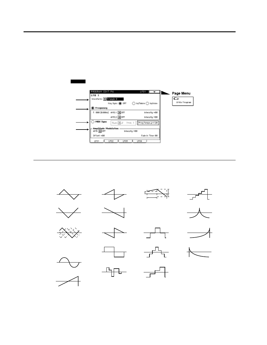
Program Edit P6
This section provides four LFOs (Low Frequency Oscillators). These LFOs can be used as modulation
sources for parameters of other sections, to create cyclic changes in the sound.
6–1: LFO 1
6–1a: Wave Form/Key Sync
Wave Form
[Triangle 0…ExpSawDown]
Settings for the general-purpose LFOs
6-1: LFO 1
AMSource
6–1a
6–1b
6–1c
6–1d
Random 2 changes in a
straight line toward a value
which is determined
randomly every 1/2 cycle.
Amplitude and the duration at
which each level is held will both
change randomly (sample & hold).
When Key Sync=ON, the
starting phase will vary
randomly.
16: Exp Saw Up
17: Exp Saw Down
15: Exp Tri
11: Step Tri 4
12: Step Tri 6
14: Step Saw 6
2: Tri Random
3: Sine
0: Triangle 0
4: Saw Up 0
5: Saw Up 180
6: Saw Down 0
7: Saw Down 180
8: Square
1/2 cycle
10: Random2 (Vector)
9: Random1(S/H)
1: Triangle 90
13: Step Saw 4
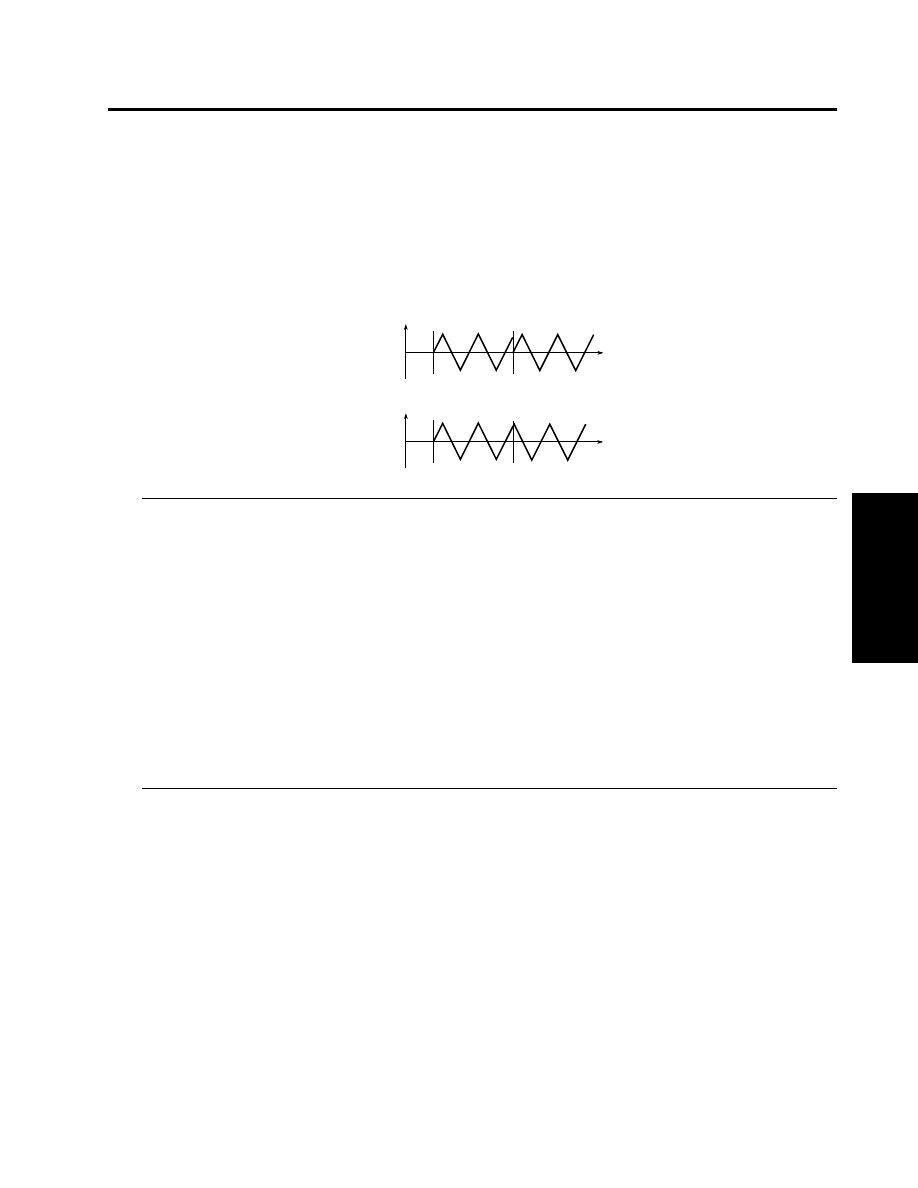
6-1: LFO 1
Parameters
Prog.
Edit
P6
Key Sync
[OFF/by TIMBRE/by VOICE]
Use the radio buttons to select the key sync setting (i.e., whether or not the phase of the LFO waveform will be
returned to its initial state when a note-on occurs).
OFF :
The LFO will operate (cycle) regardless of note-on.
by TIMBRE :
Key sync will occur for the LFOs of all voices at the time of the first note-on that
occurs in a state when no keys are on.
by VOICE :
Key sync will occur independently for the individual LFO of the voice for which
note-on occurred.
6–1b: Frequency
If you used the radio buttons to select Frequency, set the following parameters to specify the LFO
frequency.
F (Frequency)
[0(0Hz)…199(60Hz)]
Specifies the frequency of the LFO.
AMS.1 (Alternate Modulation Source 1)
[OFF…MIDI (CC#83)]
Select a modulation source 1 (☞page 64 of this manual) that will control the LFO frequency.
Intensity (Frequency AMS.1 Intensity)
[–99…+99]
Specifies the depth and direction of the effect that “AMS.1” will have on the “F (Frequency)” value.
AMS.2 (Alternate Modulation Source 2)
[OFF…MIDI (CC#83)]
Selects a modulation source 2 (☞page 64 of this manual) that will control the LFO frequency.
Intensity (Frequency AMS.2 Intensity)
[–99…+99]
Specifies the depth and direction of the effect that “AMS.2” will have on the “F (Frequency)” value.
6–1c: MIDI Sync
If you used the radio buttons to select MIDI Sync, set the following parameters to synchronize the
LFO frequency to MIDI Clock.
When the Global mode parameter “1-1d: MIDI Clock” (☞page 119 in Parameter Guide) is set to Internal the
LFO will synchronize to the tempo specified by Prog. Temp, and if it is set to External the LFO will synchronize
to the MIDI Clock messages received from an External MIDI device.
MIDI Sync Base
[
3 3 3 ]
MIDI Sync Time
[1…16]
This is relative to the tempo determined by the MIDI clock, these settings specify the note length (Base) and its
multiple (Time) that will set the period of the synchronized LFO. For example if “MIDI Sync Base” is
(quarter
note) and “MIDI Sync Time” is 4, the LFO period will be four beats.
Prog. Temp
[40…240]
Selects the tempo that will be used when MIDI Clock is set to Internal.
Note-On
Key Sync SW = Off
Key Sync SW = byTIMBRE / byVOICE
Note-On
Note-On
Note-On

6–1d: Amplitude Modulation
AMS (Alternate Modulation Source 1)
[OFF…MIDI (CC#83)]
Selects a modulation source (☞page 64 of this manual) that will control the amplitude of the LFO waveform.
Intensity (Amplitude AMS Intensity)
[–99…+99]
Specifies the depth and direction of the effect that “AMS” will have on the amplitude of the LFO waveform.
Offset
[–50…+50]
Specifies the center value of the LFO waveform.
Fade In Time
[0…99]
Specifies the time over which the amplitude of the LFO will increase from 0 until it reaches the maximum
value.
6–2: LFO 2
6–3: LFO 3
6–4: LFO 4
LFO 2, LFO 3, and LFO 4 have the same parameter as LFO 1. Refer to “6-1: LFO 1 ”
6-1: LFO 1, 6-2: LFO 2, 6-3: LFO 3, 6-4: LFO 4
The parameter value
being modulated
LFO movement determined
by Modulation Intensity
The parameter value
being modulated
LFO movement determined
by Modulation Intensity
The parameter value
being modulated
LFO movement determined
by Modulation Intensity
Offset = 0
Offset = 50
Offset = -50
AMSource
AMSource
AMSource

Program Edit P7
Here, you can make settings for the insertion effects.
For details on the parameters etc., refer to Parameter Guide page 44, “Program Edit P7.”
Program Edit P8
Here, you can make settings for the master effects.
For details on the parameters etc., refer to Parameter Guide page 44 “Program Edit P7.”
Program Edit P7, Program Edit P8
Parameters
Prog.
Edit
P7/8

Modulation Source List
00: OFF
01: EG 1
02: EG 2
03: EG 3
04: EG 4
05: Amp EG
06: LFO 1
07: LFO 2
08: LFO 3
09: LFO 4
10: Portamento
11: Velocity (Soft)
12: Velocity (Medium)
13: Velocity (Hard)
14: Note Number(Linear)
15: Note Number(Exp)
16: Note Split(Hi)
17: Note Split(Low)
18: After Touch
19: Joy Stick (X)
20: Joy Stick (+Y)
21: Joy Stick (-Y)
*22: AfterTouch+JS(+Y)
23: Ribbon (X)
24: Ribbon (+X)
25: Ribbon (-X)
26: Ribbon (Z)
27: Foot Pedal (CC#04)
28: Value Slider(CC#18)
29: MIDI (CC#19)
30: SW1 (CC#80)
31: SW2 (CC#81)
32: Foot SW (CC#82)
33: MIDI (CC#83)
* This After Touch is half of the effect of
18:AfterTouch.
Retrigger Controller List
00: OFF
01: Velocity (Soft)
02: Velocity (Medium)
03: Velocity (Hard)
04: Note Number(Linear)
05: Note Number(Exp)
06: After Touch
07: Joy Stick (X)
08: Joy Stick (+Y)
09: Joy Stick (-Y)
10: AfterTouch+JS(+Y)
11: Ribbon (X)
12: Ribbon (+X)
13: Ribbon (-X)
14: Ribbon (Z)
15: Foot Pedal (CC#04)
16: Value Slider(CC#18)
17: MIDI (CC#19)
18: SW1 (CC#80)
19: SW2 (CC#81)
20: Foot SW (CC#82)
21: MIDI (CC#83)
Data
4. Data

Data
Precautions
Regarding program change (MIDI) reception
Depending on the oscillator type used by a program, some time may be required after a program change is
received until a bank M program is actually selected. When selecting programs, please leave ample time between
the program change and the following note-on.
Regarding noise
The effect settings and the parameter settings of the oscillator used by the program may affect each
other so as to cause noise to appear in the sound. Also, if a program is played immediately (less than
one second) after it is selected, noise may appear in the output sound.
Data dump compatibility
The bank M programs created using MOSS are not compatible with the Prophecy or Z1.
Please use an insertion effect with the program
In all modes (Program, Combination, Sequencer), be sure to use an insertion effect when using a bank M program.
If you do not use an insertion effect, the output of the bank M program will diminish.
When MIDI Clock Source is set to Internal
If a bank M program is selected for any timbre in a combination, the D-mod Src “Tempo” for the AMS or effect
of the timbre program will use the Prog. Tempo setting (☞page 61 of this manual).
SOLO-TRI convert sounds (SOLO_TRI.PCG)
The SOLO_TRI.PCG sounds in the included disk are data which was created to allow the SOLO-TRI
preset sounds (☞page 14 of this manual) to be simulated on the MOSS-TRI. For some sounds, the
audible result may not be precisely identical.
Additional message
Bank S was skipped
Situation:
Bank S data was skipped while loading data. Bank S programs cannot be used.
Document Outline
- TOC
- 1. Introduction
- 2. Bank M program structure
- 3. Parameters
- Program Play P1
- Program Edit P1
- Program Edit P2
- Program Edit P3
- Program Edit P4
- Program Edit P5
- Program Edit P6
- Program Edit P7
- Program Edit P8
- 4. Data
Wyszukiwarka
Podobne podstrony:
Korg Trinity Manual Expansion Option HDR TRI
Korg Trinity Manual Expansion Option SCSI TRI
Korg Trinity Manual Expansion Option PBS TRI
Korg Trinity Manual Expansion Option DI TRI
Korg Trinity Manual Effects 1 EffectGuideTOC
Korg Trinity Manual Effects 4 Size 2
Korg Trinity Manual Operating System version 2
2 Korg Trinity Manual Basic Guide Book
Korg Trinity Manual Effects 6 Master Effects
Korg Trinity Manual Effects 2 Overview
Korg Trinity Manual Effects 5 Size 4
1b Korg Trinity Manual Parameter Guide addendum
Korg Trinity Manual Effects 3 Size 1
Korg Trinity Options Handguide by Howard Massey
Korg Trinity Audio output Masterclass (with pics)
Korg Trinity MIDI Implementation
Korg SQ 10 Service Manual
OptionScope, Finanse, Metastock, Manual Metastock 7.2 PL
Korg MS 03 Service Manual
więcej podobnych podstron