00: Piano Body/Damper
(Piano Body/Damper Simulation)
119
00: Piano Body/Damper
(Piano Body/Damper Simulation)
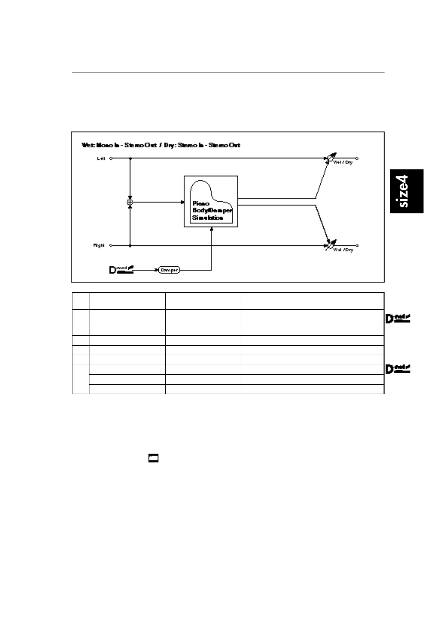
This effect simulates the resonance of the piano sound board caused by the string vibration, and also sim-
ulates the resonance of other strings that are not being played when you press the damper pedal. It will
create a very realistic sound when applied to acoustic piano sounds.
a
Sound Board Depth
0…100
Sets the intensity of resonance of the sound board.
☞
P.119
b
Damper Depth
0…100
Sets the intensity of the string resonance created when
the damper pedal is pressed.
☞
P.119
Src
None…Tempo
Modulation source of damper effect
c
Tone
1…100
Adjusts tonal quality of effect sound.
☞
P.119
d
Mid Shape
0…36
Adjusts the mid range of tonal quality.
☞
P.119
e
Tune
–50…+50
Fine tuning
☞
P.119
f
Wet/Dry
Dry, 1:99…99:1, Wet
Sets the balance between the effect and dry sounds.
Src
None…Tempo
Modulation source of effect balance
Amt
–100…+100
Modulation amount of effect balance
a: Sound Board Depth
This parameter sets the intensity of resonance of the piano sound board.
b: Damper Depth
b: Src
This parameter sets the resonance intensity of the other strings created when the
damper pedal is pressed. The Src parameter selects the modulation source from
which the damper effect is applied. Usually, select Sustain Pdl (Sustain pedal).
The effect is off when a value for the modulation source specified for the
Src parameter is 63 or smaller, and the effect is on when the value is 64 or
higher.
c: Tone
d: Mid Shape
These parameters control the tonal quality of the effect sound.
e: Tune
Since this effect simulates the resonance of the strings, the sound varies depend-
ing on the pitch. If you have changed tuning using the Master Tune, adjust this
parameter value.
01: St. Mlt.band Limiter
(Stereo Multiband Limiter)
120
01: St. Mlt.band Limiter
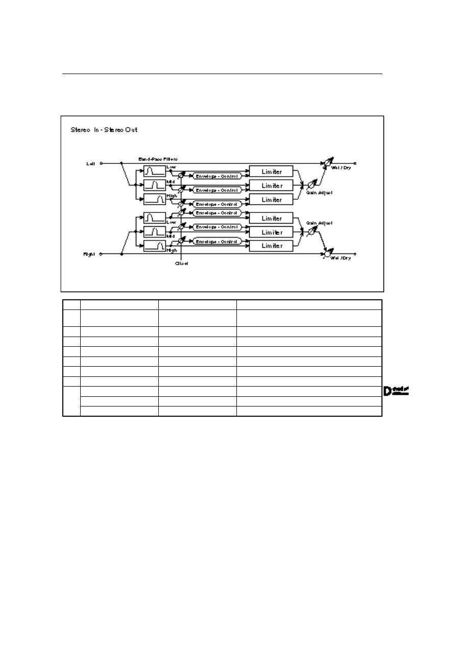
(Stereo Multiband Limiter)
This is a stereo multiband limiter.
a
Ratio
1.0:1…50.0:1, Inf:1
Sets the signal compression ratio.
☞
P.15
b
Threshold [dB]
–40…0dB
Sets the signal level above which compression is applied.
☞
P.15
c
Attack
1…100
Sets the attack time.
☞
P.16
d
Release
1…100
Sets the release time.
☞
P.16
e
Low Offset [dB]
–40…0dB
Low range gain of trigger signal
☞
P.52
f
Mid Offset [dB]
–40…0dB
Mid range gain of trigger signal
☞
P.52
g
High Offset [dB]
–40…0dB
High range gain of trigger signal
☞
P.52
h
Gain Adjust [dB]
–16…+24dB
Sets the output gain.
☞
P.15
i
Wet/Dry
Dry, 1:99…99:1, Wet
Sets the balance between the effect and dry sounds.
Src
None…Tempo
Modulation source of effect balance
Amt
–100…+100
Modulation amount of effect balance
02: OD/Hyper-Gain Wah
(Overdrive/Hyper-Gain Wah)
121
02: OD/Hyper-Gain Wah
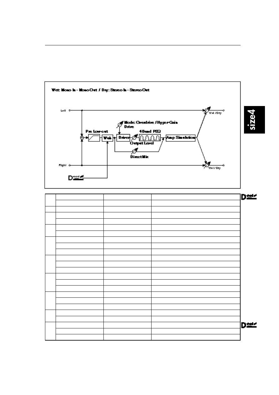
(Overdrive/Hyper-Gain Wah)
This distortion effect has two modes: overdrive and hyper-gain that produces a strong distortion. The
effect also has wah, 4-band EQ, and amp simulator. Compared to the same effect of size 1 and 2, you can
set a higher gain for this effect.
a
Wah
Off, On
Switches Wah on/off.
☞
P.56
Src
None…Tempo
Modulation source that controls wah
b
Wah Sweep Range
–10…+10
Sets the sweep range of wah.
☞
P.56
c
Drive Mode
Overdrive, Hyper-Gain
Switches between overdrive and hyper-gain distortion.
Pre Low-cut
0…10
Low range cut amount at the distortion input
☞
P.20
d
Drive
1…120
Sets the degree of distortion.
☞
P.20
Output Level
0…50
Sets the output level.
e
Band1 Cutoff [Hz]
20…1.0kHz
EQ - Band1 center frequency
Q
0.5…10.0
Band1 bandwidth
☞
P.20
Gain [dB]
–18…+18dB
Band1 gain
f
Band2 Cutoff [Hz]
50…5.00kHz
Band2 center frequency
Q
0.5…10.0
Band2 bandwidth
☞
P.20
Gain [dB]
–18…+18dB
Band2 gain
g
Band3 Cutoff [Hz]
300…10.00kHz
Band3 center frequency
Q
0.5…10.0
Band3 bandwidth
☞
P.20
Gain [dB]
–18…+18dB
Band3 gain
h
Band4 Cutoff [Hz]
500…20.00kHz
Band4 center frequency
Q
0.5…10.0
Band4 bandwidth
☞
P.20
Gain [dB]
–18…+18dB
Band4 gain
i
Direct Mix
0…50
Mixing amount of dry sound to the distortion
Speaker Simulation
Off, On
Speaker simulation on/off
j
Wet/Dry
Dry, 1:99…99:1, Wet
Sets the balance between the effect and dry sounds.
Src
None…Tempo
Modulation source of effect balance
Amt
–100…+100
Modulation amount of effect balance
03: St. Graphic 13EQ
(Stereo Graphic 13-Band EQ
)
122
03: St. Graphic 13EQ
(Stereo Graphic 13-Band EQ
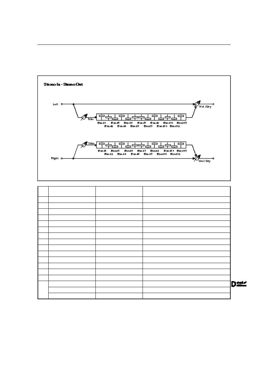
)
This is a stereo 13-band graphic equalizer that allows for finer equalization. You can select one of two set-
tings for the center frequency for each band.
a
Type
A, B
Selects a combination of center frequencies for each
band.
☞
P.59
b
Trim
0…100
Sets the input level.
c
Band1 [dB]
–18.0…+18.0dB
Sets the Band1 gain.
d
Band2 [dB]
–18.0…+18.0dB
Sets the Band2 gain.
e
Band3 [dB]
–18.0…+18.0dB
Sets the Band3 gain.
f
Band4 [dB]
–18.0…+18.0dB
Sets the Band4 gain.
g
Band5 [dB]
–18.0…+18.0dB
Sets the Band5 gain.
h
Band6 [dB]
–18.0…+18.0dB
Sets the Band6 gain.
i
Band7 [dB]
–18.0…+18.0dB
Sets the Band7 gain.
j
Band8 [dB]
–18.0…+18.0dB
Sets the Band8 gain.
k
Band9 [dB]
–18.0…+18.0dB
Sets the Band9 gain.
l
Band10 [dB]
–18.0…+18.0dB
Sets the Band10 gain.
m
Band11 [dB]
–18.0…+18.0dB
Sets the Band11 gain.
n
Band12 [dB]
–18.0…+18.0dB
Sets the Band12 gain.
o
Band13 [dB]
–18.0…+18.0dB
Sets the Band13 gain.
p
Wet/Dry
Dry, 1:99…99:1, Wet
Sets the balance between the effect and dry sounds.
Src
None…Tempo
Modulation source of effect balance
Amt
–100…+100
Modulation amount of effect balance
04: Vocoder
123
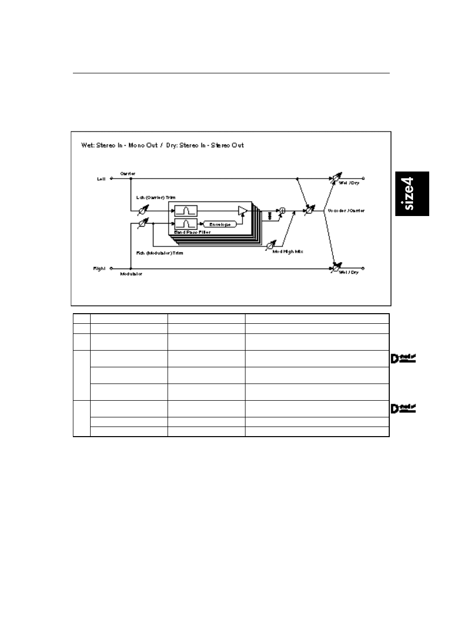
04: Vocoder
This effect adds characteristics of other signals (Modulator) to the input signal (Carrier). The Carrier is
input to the left channel, and the Modulator is input to the right channel. A sound with a lot of harmonics
is suitable for a carrier, while a unique effect sound is suitable for a modulator.
a
Lch (Carrier) Trim
0…100
Input level of left channel (Carrier)
b
Rch (Modulator) Trim
0…100
Input level of right channel (Modulator)
c
Mod High Mix
0…100
Output level of high-range component of right channel
(Modulator)
☞
P.123
d
Vocoder/Carrier
0…100
Balance between vocoder output and left channel (Car-
rier)
☞
P.123
Src
None…Tempo
Modulation source of the balance between vocoder out-
put and left channel (Carrier)
Amt
–100…+100
Modulation amount of the balance between vocoder out-
put and left channel (Carrier)
e
Wet/Dry
Dry, 1:99…99:1, Wet
Sets the balance between the effect and dry sounds.
☞
P.123
Src
None…Tempo
Modulation source of effect balance
Amt
–100…+100
Modulation amount of effect balance
c: Mod High Mix
This parameter sets the high-range output level of the right channel sound
(Modulator). Raise this value to enhance the characteristics of the modulator.
d: Vocoder/Carrier
e: Wet/Dry
The Vocoder/Carrier parameter sets the balance between the vocoder sound
and the left channel sound (Carrier). The Wet/Dry parameter sets the balance
between the effect and dry sound.
If you wish to change the intensity of the vocoder effect, select “Wet” for Wet/
Dry, and adjust the balance using the Vocoder/Carrier parameter.
05: St. Harmonic Chorus
(Stereo Harmonic Chorus)
124
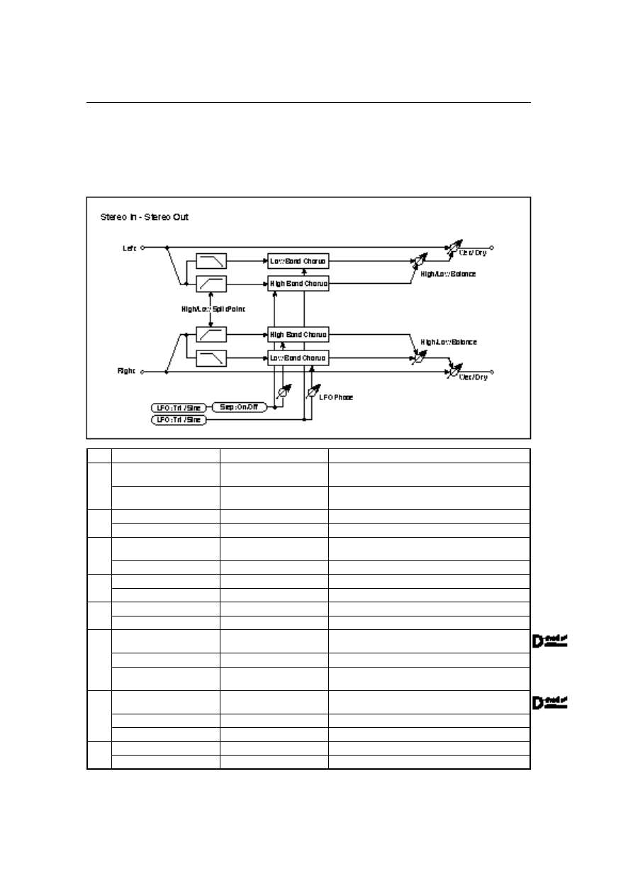
05: St. Harmonic Chorus
(Stereo Harmonic Chorus)
This is a stereo harmonic chorus effect that applies chorus separately to the high and low ranges of the
input signal. You can set the parameters for the low and high range chorus individually. You can also use
the high-range chorus as a step chorus employing a step-shape LFO waveform. Thick, fine chorus effects
can be created when it is applied to strings or ensemble sounds.
a
LFO Waveform
Triangle, Sine
Selects LFO waveform.
b
LFO Phase [degree]: Low
–180…+180
The difference between low-range left and right LFO
phase.
☞
P.67
High
–180…+180
The difference between high-range left and right LFO
phase.
c
LFO Frequency [Hz]: Low
0.02…20.00Hz
Low-range LFO speed
High
0.02…20.00Hz
High-range LFO speed
d
LFO Step Freq [Hz]
(LFO Step Frequency)
Off, On
Determines whether or not the high-range LFO is step-
shaped.
☞
P.125
High
0.05…50.00Hz
Speed at which the LFO waveform becomes step-shaped
e
Pre Delay [msec]: Low
0.0…50.0msec
Low range delay time
High
0.0…50.0msec
High range delay time
f
Depth: Low
0…100
Depth of low range LFO modulation
High
0…100
Depth of high range LFO modulation
g
LFO Freq D-mod
(LFO Frequency D-mod)
Low, High, Both
Selects only low-range, high-range, or both ranges for
LFO speed modulation.
☞
P.125
Src
None…Tempo
Modulation source of LFO speed
Amt
–20.00 (–80.00) …+20.00Hz
(+80.00)
Modulation amount of LFO speed
h
Depth D-mod
Low, High, Both
Selects only low-range, high-range, or both ranges for
LFO modulation depth.
☞
P.125
Src
None…Tempo
Modulation source of LFO modulation depth
Amt
–100…+100
Modulation amount of LFO modulation depth
i
High/Low Split Point
1…100
Splits frequencies into low and high ranges
☞
P.125
High/Low Balance
Low, 1…99, High
Sets output balance between low and high ranges.
05: St. Harmonic Chorus
(Stereo Harmonic Chorus)
125
j
Wet/Dry
Dry, 1:99…99:1, Wet
Sets the balance between the effect and dry sounds.
Src
None…Tempo
Modulation source of effect balance
Amt
–100…+100
Modulation amount of effect balance
d: LFO Step Freq [Hz]
d: High
This parameter determines whether or not the waveform of the high-range LFO
should be step-shaped. Changing the d: High value will allow you to adjust the
width of the steps.
g: LFO Freq D-mod
This parameter determines whether the LFO speed dynamic modulation is
applied to the low range, high range, or both ranges. When d: LFO Step Freq is
On, the waveform of the high-range LFO will be step-shaped, and dynamic
modulation will be applied to the speed of this step-shaped LFO (width of
steps).
h: Depth D-mod
This parameter determines whether the dynamic modulation of LFO modula-
tion depth is applied to the low range, high range, or both ranges.
i: High/Low Split Point
This parameter sets the split point (frequency) between high and low ranges.
Split signals are input to the respective chorus block.
06: Multitap Chorus/Dly
(Multitap Chorus/Delay)
126
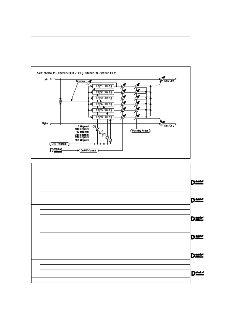
06: Multitap Chorus/Dly
(Multitap Chorus/Delay)
This effect has six chorus blocks with different LFO phases. You can produce a complex stereo image by
setting a different delay time and depth for each block. You can control the delay output level via a mod-
ulation source.
a
LFO Frequency [Hz]
0.02…13.00Hz
LFO speed
b
Tap1(000) [msec]
0…570msec
Tap1 (LFO phase = 0) delay time
Depth
0…30
Depth of Tap1 chorus
Status
Always On, Always Off,
On
→
Off(dm), Off
→
On(dm)
Selects on, off, or modulation source for the control of
Tap1 output.
☞
P.127
c
Tap2(180) [msec]
0…570msec
Tap2 (LFO phase = 180) delay time
Depth
0…30
Depth of Tap2 chorus
Status
Always On, Always Off,
On
→
Off(dm), Off
→
On(dm)
Selects on, off, or modulation source for the control of
Tap2 output.
☞
P.127
d
Tap3(060) [msec]
0…570msec
Tap3 (LFO phase = 60) delay time
Depth
0…30
Depth of Tap3 chorus
Status
Always On, Always Off,
On
→
Off(dm), Off
→
On(dm)
Selects on, off, or modulation source for the control of
Tap3 output.
☞
P.127
e
Tap4(240) [msec]
0…570msec
Tap4 (LFO phase = 240) delay time
Depth
0…30
Depth of Tap4 chorus
Status
Always On, Always Off,
On
→
Off(dm), Off
→
On(dm)
Selects on, off, or modulation source for the control of
Tap4 output.
☞
P.127
f
Tap5(120) [msec]
0…570msec
Tap5 (LFO phase = 120) delay time
Depth
0…30
Depth of Tap5 chorus
Status
Always On, Always Off,
On
→
Off(dm), Off
→
On(dm)
Selects on, off, or modulation source for the control of
Tap5 output.
☞
P.127
g
Tap6(300) [msec]
0…570msec
Tap6 (LFO phase = 300) delay time
Depth
0…30
Depth of Tap6 chorus
Status
Always On, Always Off,
On
→
Off(dm), Off
→
On(dm)
Selects on, off, or modulation source for the control of
Tap6 output.
☞
P.127
h
Panning Preset
1, 2, 3, 4
Specifies the stereo image of each Tap.
☞
P.127
06: Multitap Chorus/Dly
(Multitap Chorus/Delay)
127
i
Tap1 Feedback
–100…+100
Tap1 feedback amount
Src
None…Tempo
Modulation source for the Tap output level, feedback
amount, and effect balance
☞
P.127
Amt
–100…+100
Modulation amount of Tap1 feedback amount
☞
P.127
j
Wet/Dry
Dry, 1:99…99:1, Wet
Balance between effect sound and dry sound
Amt
–100…+100
Modulation amount of effect balance
☞
P.127
b: Status
c: Status
d: Status
e: Status
f: Status
g: Status
These parameters set the output status of each Tap.
Always On: Output is always on. (No modulation)
Always Off: Output is always off. (No modulation)
On
→
Off (dm): Output level is switched from on to off depending on the modu-
lation source.
Off
→
On (dm): Output level is switched from off to on depending on the modu-
lation source.
Combining these parameters, you can change from 4-phase chorus to two-tap
delay by crossfading them gradually via the modulation source during a perfor-
mance.
h: Panning Preset
This parameter selects combinations of stereo images of the tap outputs.
i: Src
i: Amt
j: Amt
Tap output level, feedback amount and effect balance are controlled simulta-
neously via a modulation source.
07: Stereo Ensemble
128
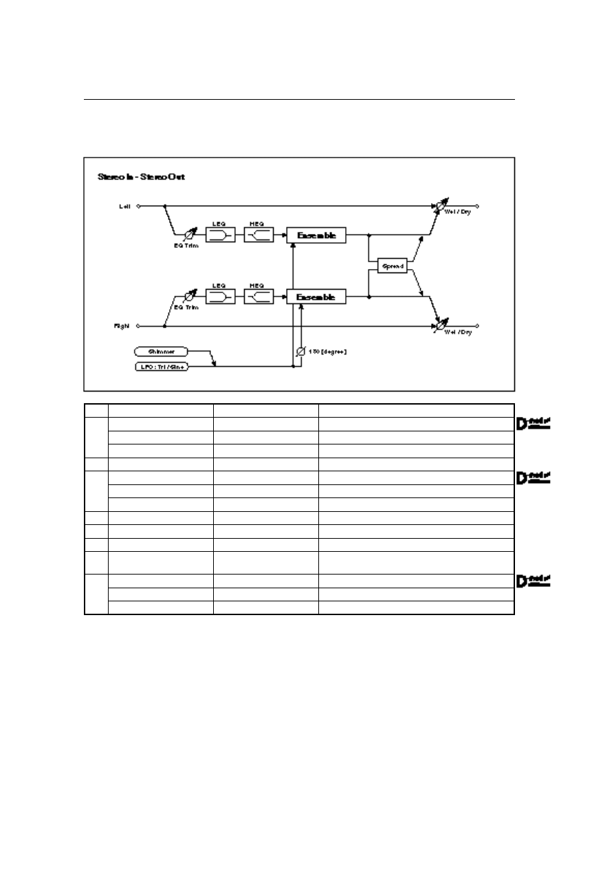
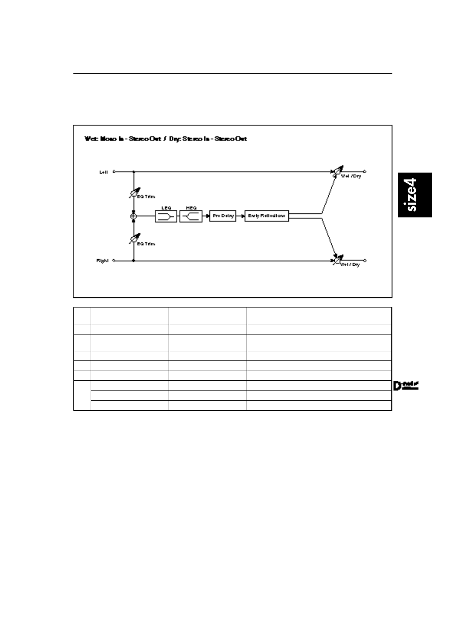
07: Stereo Ensemble
This is a stereo ensemble effect that has three chorus blocks each for the left and right channels.
a
LFO Waveform
Triangle, Sine
Selects LFO waveform.
b
Speed
1…100
LFO speed
Src
None…Tempo
Modulation source of LFO speed
Amt
–100…+100
Modulation amount of LFO speed
c
Shimmer
0…100
Amount of shimmering of LFO waveform
☞
P.32
d
Depth
0…100
Depth of LFO modulation
Src
None…Tempo
Modulation source of LFO modulation depth
Amt
–100…+100
Modulation amount of LFO modulation depth
e
EQ Trim
0…100
EQ input level
f
Pre LEQ Gain [dB]
–15.0…+15.0dB
Low EQ gain
g
Pre HEQ Gain [dB]
–15.0…+15.0dB
High EQ gain
h
Spread
–100…+100
Sets the width of the stereo image of the effect sound.
☞
P.67
i
Wet/Dry
Dry, 1:99…99:1, Wet
Sets the balance between the effect and dry sounds.
Src
None…Tempo
Modulation source of effect balance
Amt
–100…+100
Modulation amount of effect balance
08: St. Tempo Flanger
(Stereo Tempo Flanger)
129
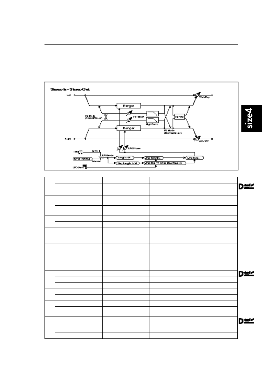
08: St. Tempo Flanger
(Stereo Tempo Flanger)
This is a stereo tempo flanger. You can select random or step waveforms for the LFO, and synchronize the
speed of the random/step waveform with tempo. Also, synchronizing the LFO to note-on messages will
produce a flanging effect with a fixed timing.
a
LFO Sync
Off, On
LFO reset on/off
☞
P.111
Src
None…Tempo
Modulation source that resets LFO
b
Delay Time [msec]
0.0…50.0msec
Delay time from the original sound
c
LFO Waveform
Triangle, Sine, Step-Tri,
Step-Sin, Random
Selects LFO waveform.
☞
P.72
LFO Shape
–100…+100
Determines how much the LFO waveform is changed.
☞
P.33
d
LFO Lch Phase [deg]
–180…+180
Left LFO phase after reset
☞
P.111
Rch Phase [deg]
–180…+180
Right LFO phase after reset
e
LFO Mode
Manual, D-mod
Switches between the specified tempo and clock sync.
☞
P.34
Src(fixed)
Tempo
Source when LFO Mode = D-mod (fixed to Tempo)
f
Tempo [beat/min]
30…250 beat/min
Tempo when LFO Mode = Manual
☞
P.34
Length
1…16 / 1…16
Sets the LFO cycle. LFO Cycle = Length x Whole Note.
☞
P.34
Step
1…16 / 1…32
Sets the LFO step cycle. LFO step Cycle = Length x
Whole Note.
g
Depth
0…100
Depth of LFO modulation
Src
None…Tempo
Modulation source of LFO modulation depth
Amt
–100…+100
Modulation amount of LFO modulation depth
h
Feedback
–100…+100
Feedback amount
☞
P.33
FB Mode
Normal, Cross
Sets feedback routing.
☞
P.71
i
High Damp [%]
0…100%
Feedback damping amount in the high range
☞
P.33
Spread
–100…+100
Sets the width of the stereo image of effect sound.
☞
P.67
j
Wet/Dry
–Wet…–1:99, Dry,
1:99…Wet
Sets the balance between the effect and dry sounds.
☞
P.26, 33
Src
None…Tempo
Modulation source of effect balance
Amt
–100…+100
Modulation amount of effect balance
09: St. Tempo Phaser
(Stereo Tempo Phaser)
130
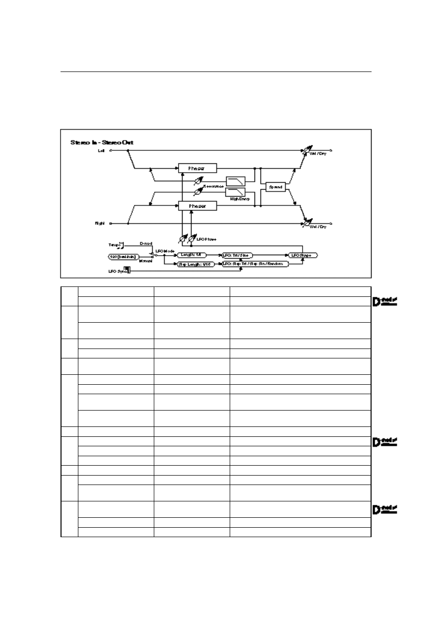
09: St. Tempo Phaser
(Stereo Tempo Phaser)
This is a stereo tempo phaser. You can select random or step waveforms for the LFO, and synchronize the
speed of the random/step waveform with tempo. Also, synchronizing the LFO to note-on messages will
produce a phasing effect with a fixed timing.
a
LFO Sync
Off, On
LFO reset on/off
☞
P.111
Src
None…Tempo
Modulation source that resets LFO
b
LFO Waveform
Triangle, Sine, Step-Tri,
Step-Sin, Random
Selects LFO waveform.
☞
P.72
LFO Shape
–100…+100
Determines how much the LFO waveform is changed.
☞
P.33
c
LFO Lch Phase [deg]
–180…+180
Left LFO phase after reset
☞
P.111
Rch Phase [deg]
–180…+180
Right LFO phase after reset
d
LFO Mode
Manual, D-mod
Switches between the specified tempo and clock sync.
☞
P.34
e
Src(fixed)
Tempo
Source when LFO Mode = D-mod (fixed to Tempo)
Tempo [beat/min]
30…250 beat/min
Tempo when LFO Mode = Manual
☞
P.34
Length
1…16 / 1…16
Sets the LFO cycle. LFO Cycle = Length x Whole Note.
☞
P.34
Step
1…16 / 1…32
Sets the LFO step cycle. LFO step Cycle = Length x
Whole Note.
f
Manual
0…100
Sets the center frequency to which the effect is applied.
g
Depth
0…100
Depth of LFO modulation
Src
None…Tempo
Modulation source of LFO modulation depth
Amt
–100…+100
Modulation amount of LFO modulation depth
h
Resonance
–100…+100
Sets resonance amount.
☞
P.36
i
High Damp [%]
0…100%
Resonance damping amount in the high range
☞
P.36
Spread
–100…+100
Sets the width of the stereo image of the effect sound.
☞
P.67
j
Wet/Dry
–Wet…–1:99, Dry,
1:99…Wet
Sets the balance between the effect and dry sounds.
☞
P.36
Src
None…Tempo
Modulation source of effect balance
Amt
–100…+100
Modulation amount of effect balance
10: St. Pitch Shifter
(Stereo Pitch Shifter)
131
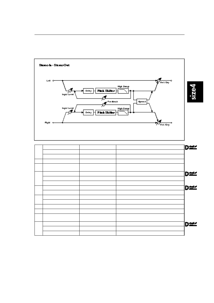
10: St. Pitch Shifter
(Stereo Pitch Shifter)
This is a stereo pitch shifter. The pitch shift amount for the left and right channels can be reversed from
each other.
a
Input Level
0…100
Sets input level to the effect.
Src
None…Tempo
Selects the modulation source of input level.
Amt
–100…+100
Modulation amount of input level
b
Mode
Slow, Medium, Fast
Switches Pitch Shifter mode.
☞
P.98
c
L/R Pitch
Normal, Up/Down
Determines whether or not the L/R pitch shift amount is
inverted.
d
Pitch Shift [1/2tone]
–24…+24
Sets the pitch shift amount in steps of a semitone.
☞
P.99
Src
None…Tempo
Modulation source of pitch shift amount
Amt
–24…+24
Modulation amount of pitch shift amount
e
Fine [cent]
–100…+100cent
Sets the pitch shift amount in steps of one cent.
☞
P.99
Amt
–100…+100cent
Modulation amount of pitch shift amount
f
Lch Delay [msec]
0…1000msec
Sets the delay time for the left channel.
☞
P.99
Rch Delay [msec]
0…1000msec
Sets the delay time for the right channel.
g
Feedback
–100…+100
Sets the feedback amount.
☞
P.99
h
High Damp [%]
0…100%
Damping amount in the high range
i
Spread
–100…+100
Sets the width of the stereo image of the effect sound.
☞
P.67
j
Wet/Dry
Dry, 1:99…99:1, Wet
Sets the balance between the effect and dry sounds.
Src
None…Tempo
Modulation source of effect balance
Amt
–100…+100
Modulation amount of effect balance
c: L/R Pitch
When you select Up/Down for this parameter, the pitch shift amount for the left
channel will be reversed. If the pitch shift amount is positive, the pitch of the left
channel is raised, and the pitch of the right channel is lowered.
11: 2Band Pitch Shifter
132
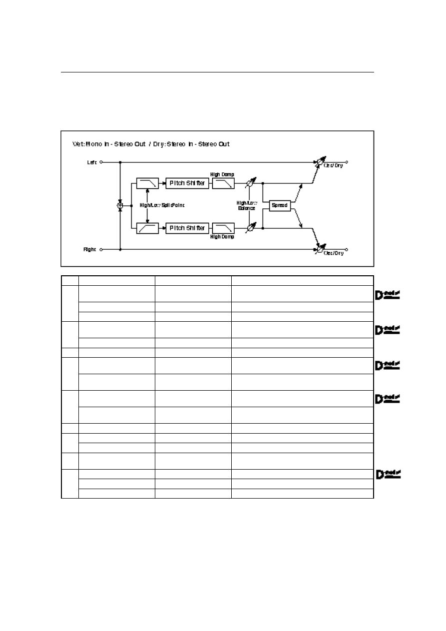
11: 2Band Pitch Shifter
This pitch shifter sets an individual shift amount for the high and low input signal ranges. If you apply a
detune effect to the high range of a string sound, and add the lower octave to the low range, a large
ensemble sound is produced.
a
Mode
Slow, Medium, Fast
Switches pitch shifter mode.
☞
P.98
b
Low Pitch [1/2tone]
–24…+24
Sets pitch shift amount for the low range in steps of a
semitone.
☞
P.99
Src
None…Tempo
Modulation source of pitch shift amount
Amt
–24…+24
Modulation amount of pitch shift amount for the low range
c
Low Fine [cent]
–100…+100cent
Sets pitch shift amount for the low range in steps of one
cent.
☞
P.99
Amt
–100…+100cent
Modulation amount of pitch shift amount for the low range
d
Low High Damp [%]
0…100%
High component damping amount in the low range
e
High Pitch [1/2tone]
–24…+24
Sets pitch shift amount for the high range in steps of a
semitone.
☞
P.99
Amt
–24…+24
Modulation amount of pitch shift amount for the high
range
f
High Fine [cent]
–100…+100cent
Sets pitch shift amount for the low range in steps of one
cent.
☞
P.99
Amt
–100…+100cent
Modulation amount of pitch shift amount for the high
range
g
High High Damp [%]
0…100%
High component damping amount in the high range
h
High/Low Split Point
1…100
Splits frequencies between low and high ranges
High/Low Balance
Low, 1:99…99:1, High
Output balance between low and high ranges
i
Spread
–100…+100
Sets the width of the stereo image of the effect sound.
☞
P.132
j
Wet/Dry
Dry, 1:99…99:1, Wet
Sets the balance between the effect and dry sounds.
Src
None…Tempo
Modulation source of effect balance
Amt
–100…+100
Modulation amount of effect balance
i: Spread
This parameter specifies the width of the stereo image of the effect sound. With
a value of +100, the low range signal is output from the left channel and the high
range signal from the right channel. With a value of 0, both channels will output
a mix signal of low and high-range signals. With a negative value, the output
channel of the low and high-range signals will be reversed.
12: Rotary Speaker OD
(Rotary Speaker Overdrive)
133
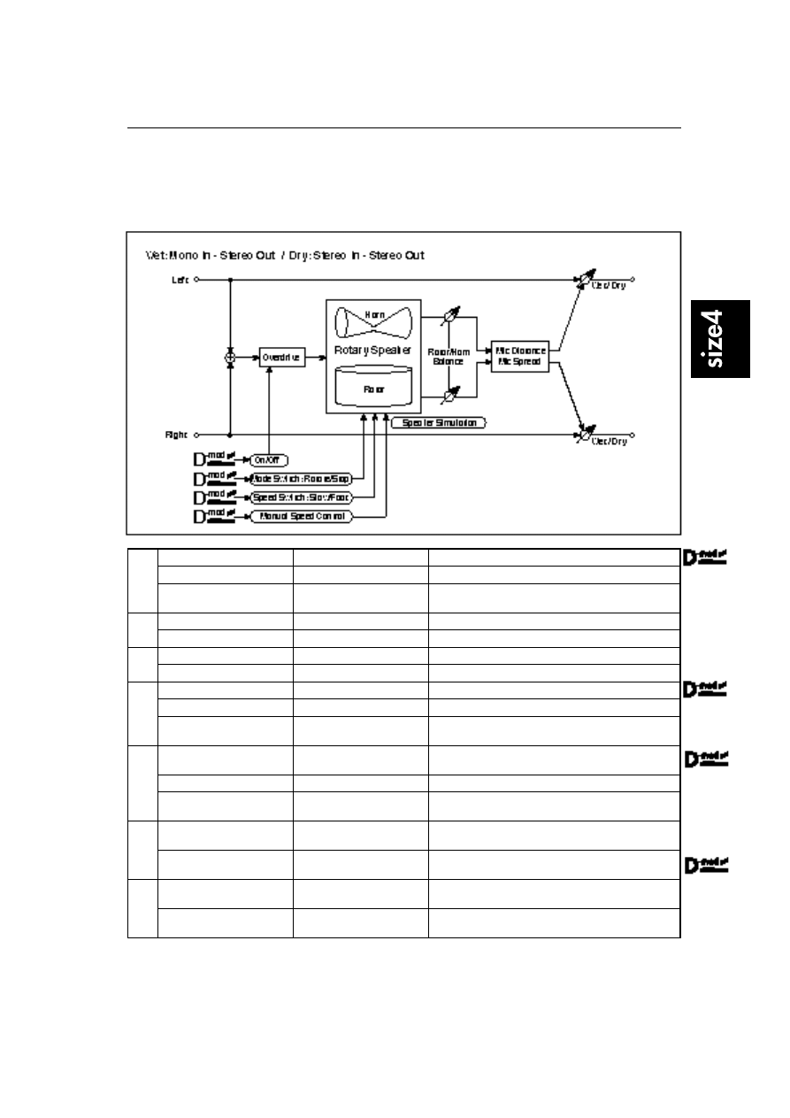
12: Rotary Speaker OD
(Rotary Speaker Overdrive)
This is a stereo rotary speaker effect. It has an internal speaker simulator that simulates overdrive (recre-
ating the amp distortion) and characteristics of the rotary speaker, producing a very realistic rotary
speaker sound.
a
Overdrive
Off, On
Switches overdrive on/off.
Src
None…Tempo
Modulation source that switches overdrive on/off.
Sw
Momentary, Toggle
Selects the switching mode of the modulation source that
switches overdrive on/off.
☞
P.134
b
Overdrive Gain
0…50
Determines the degree of distortion.
Overdrive Level
0…50
Overdrive output level
c
Overdrive Tone
0…15
Tonal quality of overdrive
Speaker Simulator
Off, On
Switches speaker simulation on/off.
d
Mode Switch
Rotate, Stop
Switches between speaker rotation and stop.
Src
None…Tempo
Modulation source that toggles between rotation and stop
Sw
Momentary, Toggle
Selects the switching mode of the modulation source that
toggles between rotation and stop.
☞
P.103
e
Speed Switch
Slow, Fast
Switches the speaker rotation speed between slow and
fast.
Src
None…Tempo
Modulation source that toggles between slow and fast.
Sw
Momentary, Toggle
Selects the switching mode of the modulation source that
toggles between slow and fast.
☞
P.44
f
Rotor/Horn Balance
Rotor, 1…99, Horn
Sets the volume level balance between the low-range
rotor and high-range horn.
ManualSpeedControl
None…Tempo
Sets the modulation source in case the rotation speed is
changed directly.
☞
P.103
g
Rotor Acceleration
0…100
How quickly the rotor rotation speed in the low range is
switched.
☞
P.44
Rotor Ratio
Stop, 0.50…2.00
Adjusts the (low-range side) rotor rotation speed. Stan-
dard value is 1.0. Selecting “Stop” will stop the rotation.
12: Rotary Speaker OD
(Rotary Speaker Overdrive)
134
h
Horn Acceleration
0…100
How quickly the horn rotation speed in the high range is
switched.
☞
P.44
Horn Ratio
Stop, 0.50…2.00
Adjusts the (high-range side) horn rotation speed. Stan-
dard value is 1.0. Selecting “Stop” will stop the rotation.
i
Mic Distance
0…50
Distance between the microphone and rotary speaker.
☞
P.103
Mic Spread
0…50
Angle of left and right microphones
j
Wet/Dry
Dry, 1:99…99:1, Wet
Sets the balance between the effect and dry sounds.
Src
None…Tempo
Modulation source of effect balance
Amt
–100…+100
Modulation amount of effect balance
a: Sw
This parameter determines how to switch on/off the overdrive via a modula-
tion source.
When Sw = Momentary, overdrive is applied only when a pedal or joystick is
held in position.
Only when the value for the modulation source is 64 or higher, the over-
drive effect is applied.
When Sw = Toggle, overdrive is turned on/off each time the pedal or joystick is
operated.
Each time when the value for the modulation source exceeds 64, the over-
drive effect is switched on/off.
13: Early Reflections
135
13: Early Reflections
This is a stereo early reflection effect. Compared to the Early Reflections of size 2, this effect has twice the
number of reflections, thus creating a smooth, dense sound.
a
Type
Sharp, Loose, Modulated,
Reverse
Selects the decay curve for the early reflection.
☞
P.47
b
ER Time [msec]
10…1600msec
Time length of early reflection
c
Pre Delay [msec]
0…200msec
Time taken from the original sound to the first early reflec-
tion
d
EQ Trim
0…100
Input level of EQ applied to the effect sound
e
Pre LEQ Gain [dB]
–15.0…+15.0dB
Low range EQ gain
f
Pre HEQ Gain [dB]
–15.0…+15.0dB
High range EQ gain
g
Wet/Dry
Dry, 1:99…99:1, Wet
Sets the balance between the effect and dry sounds.
Src
None…Tempo
Modulation source of effect balance
Amt
–100…+100
Modulation amount of effect balance
14: L/C/R Long Delay
136
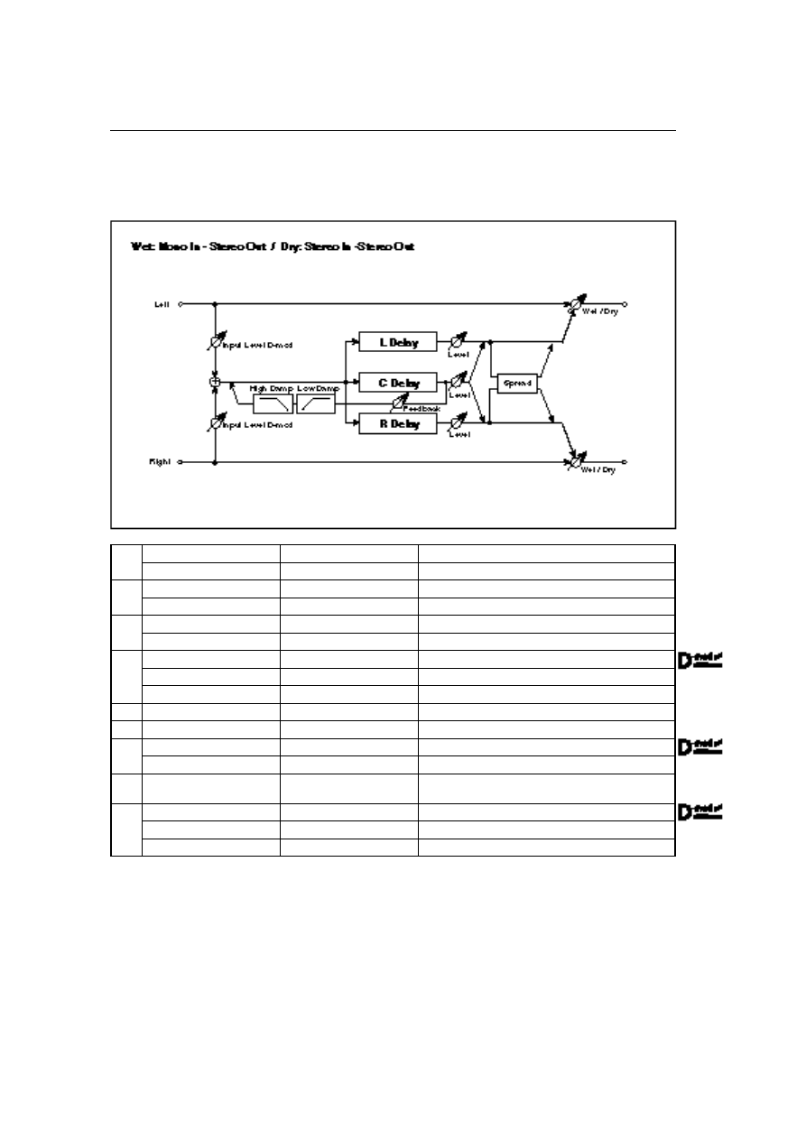
14: L/C/R Long Delay
This multitap delay outputs three Tap signals to left, right and center respectively. You can set a maxi-
mum of 2,730msec for the delay time.
a
L Delay Time [msec]
0…2730msec
Sets the TapL delay time.
Level
0…50
TapL output level
b
C Delay Time [msec]
0…2730msec
Sets the TapC delay time.
Level
0…50
TapC output level
c
R Delay Time [msec]
0…2730msec
Sets the TapR delay time.
Level
0…50
TapR output level
d
Feedback
–100…+100
Sets the Tap2 feedback amount.
Src
None…Tempo
Modulation source of the Tap2 feedback amount
Amt
–100…+100
Modulation amount of the Tap2 feedback amount
e
High Damp [%]
0…100%
Damping amount in the high range
☞
P.45
f
Low Damp [%]
0…100%
Damping amount in the low range
☞
P.45
g
Input Level D-mod: Src
None…Tempo
Modulation source of the input level
☞
P.45
Amt
–100…+100
Modulation amount of the input level
h
Spread
0…50
Sets the width of the stereo image of the effect sound.
☞
P.67
i
Wet/Dry
Dry, 1:99…99:1, Wet
Sets the balance between the effect and dry sounds.
Src
None…Tempo
Modulation source of effect balance
Amt
–100…+100
Modulation amount of effect balance

15: Stereo Long Delay
137
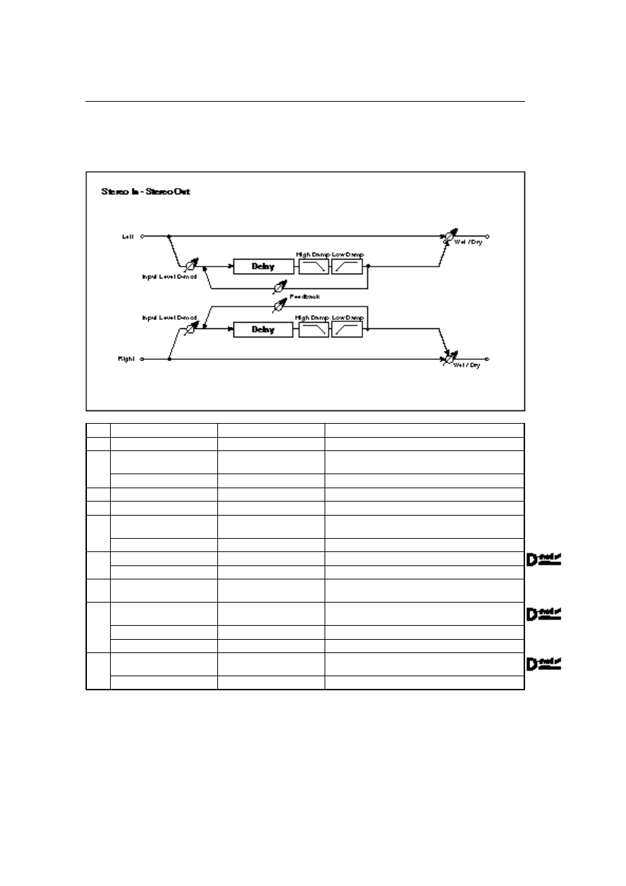
15: Stereo Long Delay
This is a stereo delay, and can by used as a cross-feedback delay effect in which the delay sounds cross
over between left and right by changing the feedback routing. You can set a maximum of 1,360msec for
the delay time.
a
Stereo/Cross
Stereo, Cross
Switches between stereo delay and cross-feedback delay.
b
L Delay Time [msec]
0.0…1360.0msec
Sets the delay time for the left channel.
c
R Delay Time [msec]
0.0…1360.0msec
Sets the delay time for the right channel.
d
Feedback
–100…+100
Sets feedback amount.
Src
None…Tempo
Modulation source of feedback amount
Amt
–100…+100
Modulation amount of feedback amount
e
High Damp [%]
0…100%
Damping amount in the high range
☞
P.45
f
Low Damp [%]
0…100%
Damping amount in the low range
☞
P.45
g
Input Level D-mod: Src
None…Tempo
Modulation source of the input level
☞
P.45
Amt
–100…+100
Modulation amount of the input level
h
Spread
–100…+100
Sets the width of the stereo image of the effect sound.
☞
P.67
Src
None…Tempo
Modulation source of stereo image width of the effect
sound
Amt
–100…+100
Modulation amount of stereo image width of the effect
sound
i
Wet/Dry
Dry, 1:99…99:1, Wet
Sets the balance between the effect and dry sounds.
Src
None…Tempo
Modulation source of effect balance
Amt
–100…+100
Modulation amount of effect balance
16: Dual Long Delay
138
16: Dual Long Delay
This 2-channel delay allows you to set the delay time for left and right channels independently. You can
set a maximum of 1,360msec for the delay time.
a
L Delay Time [msec]
0.0…1360.0msec
Sets the delay time for the left channel.
b
L Feedback
–100…+100
Sets the feedback amount for the left channel.
c
L High Damp [%]
0…100%
Damping amount in the high range for the left channel
☞
P.45
L Low Damp [%]
0…100%
Damping amount in the low range for the left channel
d
R Delay Time [msec]
0.0…1360.0msec
Sets the delay time for the right channel.
e
R Feedback
–100…+100
Sets the feedback amount for the right channel.
f
R High Damp [%]
0…100%
Damping amount in the high range for the right channel
☞
P.45
R Low Damp [%]
0…100%
Damping amount in the low range for the right channel
g
Input Level D-mod: Src
None…Tempo
Modulation source of the left and right input level
☞
P.45
Amt L
–100…+100
Modulation amount of the input level for the left channel
h
Amt R
–100…+100
Modulation amount of the input level for the right channel
☞
P.45
i
L Wet/Dry
Dry, 1:99…99:1, Wet
Sets the balance between the effect and dry sounds for
the left channel.
Src
None…Tempo
Modulation source of left/right effect balance
Amt
–100…+100
Modulation amount of effect balance for the left channel
j
R Wet/Dry
Dry, 1:99…99:1, Wet
Sets the balance between the effect and dry sounds for
the right channel.
Amt
–100…+100
Modulation amount of effect balance for the right channel
17: St. Tempo Delay
(Stereo Tempo Delay)
139
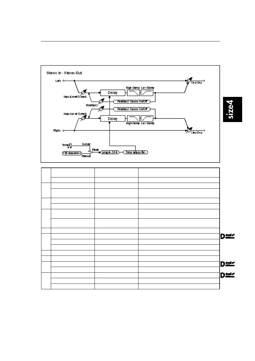
17: St. Tempo Delay
(Stereo Tempo Delay)
This is a stereo tempo delay.
a
Mode
Manual, D-mod
Switches between the specified tempo and clock sync.
☞
P.109
Src (fixed)
Tempo
Source when LFO Mode = D-mod (fixed to Tempo)
b
Tempo [beat/min]
30…250 beat/min
Tempo when LFO Mode = Manual
☞
P.109
Length
1…96 / 1…96
Sets the delay time. Delay time = Length x Whole Note.
☞
P.109
c
Time Adjust [%]
–10.00…+10.00%
Fine adjustment of delay time
Delay 1362ms
OVER!!
Delay time upper limit/error indication
☞
P.109
d
Feedback Count
Off, On
Selects whether the number of feedback times is counted
or not.
☞
P.109
Src (fixed)
Gate1
Source that triggers the counting of the feedback time
(fixed to Gate1)
e
Count [times]
0…96
Number of feedback times
☞
P.109
f
Feedback
–100…+100
Sets the feedback amount.
Src
None…Tempo
Modulation source of feedback amount
Amt
–100…+100
Modulation amount of feedback amount
g
High Damp [%]
0…100%
Damping amount in the high range
☞
P.45
h
Low Damp [%]
0…100%
Damping amount in the low range
☞
P.45
i
Input Level D-mod: Src
None…Tempo
Modulation source of the input level
☞
P.45
Amt
–100…+100
Modulation amount of the input level
j
Wet/Dry
Dry, 1:99…99:1, Wet
Sets the balance between the effect and dry sounds.
Src
None…Tempo
Modulation source of effect balance
Amt
–100…+100
Modulation amount of effect balance
18: Hold Delay
140
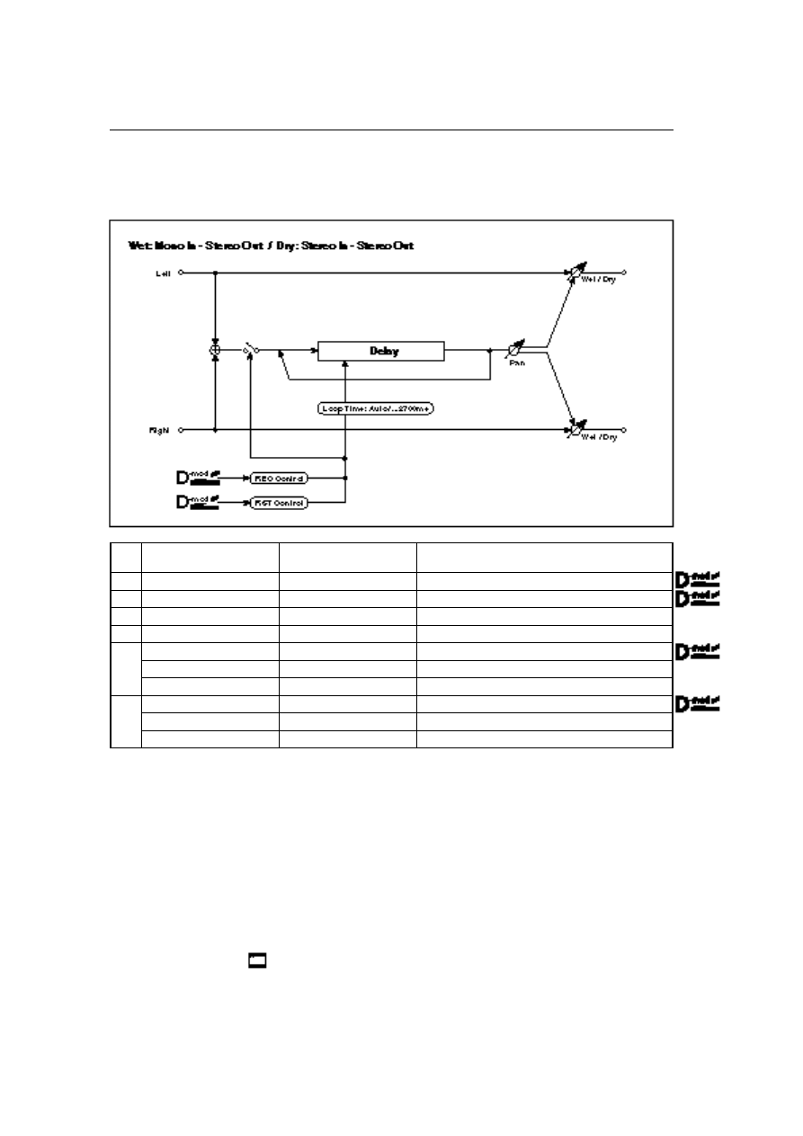
18: Hold Delay
This effect records the input signal and plays it back repeatedly. You can control the start of recording and
reset via a modulation source. Easy to use for real-time performances.
a
Loop Time [msec]
Auto, 1…2700msec
Sets Automatic loop time setup mode or specifies loop
time.
☞
P.140
b
REC Control Src
None…Tempo
Selects control source for recording.
☞
P.140
c
RST Control Src
None…Tempo
Selects control source for reset.
☞
P.141
d
Manual REC Control
REC Off, REC On
Recording switch
☞
P.140
e
Manual RST Control
Off, RESET
Reset switch
☞
P.141
f
Pan
L100…L1, C, R1…R100
Sets the stereo image of the effect.
Src
None…Tempo
Modulation source of stereo image of the effect
Amt
–100…+100
Modulation amount of stereo image of the effect
g
Wet/Dry
Dry, 1:99…99:1, Wet
Sets the balance between the effect and dry sounds.
Src
None…Tempo
Modulation source of effect balance
Amt
–100…+100
Modulation amount of effect balance
a: Loop Time [msec]
With Auto, the loop time is automatically set. Otherwise, you can specify the
loop time.
When Auto is selected, the Loop Time is automatically set to the time it takes for
a performance recorded while the Modulation Source or Manual Rec Control is
on. However, if the time length exceeds 2,700msec, the loop time will be auto-
matically set to 2,700msec.
b: REC Control Src
d: Manual REC Control
REC Control Src selects the modulation source that controls recording. If this
modulation is on, or if Manual REC Control is set to REC On, you can record the
input signal. If a recording has already been carried out, additional signals will
be overdubbed.
The effect is off when a value for the modulation source specified for the
REC Control Src parameter is 63 or smaller, and the effect is on when the
value is 64 or higher.
18: Hold Delay
141
c: RST Control Src
e: Manual RST Control
The RST Control Src parameter specifies the modulation source that controls the
reset operation. When you set this modulatoin source to On, or Manual RST
Control to RST On, you can erase what you recorded. If the Loop Time parame-
ter has been set to Auto, the loop time is also reset.
The effect is off when a value for the modulation source specified for the
RST Control Src parameter is 63 or smaller, and the effect is on when the
value is 64 or higher.
“Hold” procedure (when Loop Time = Auto)
Select the following options for each parameter:
1
a: Loop Time [msec] = Auto
b: REC Control Src = JS(+Y)
c: RST Control Src = JS(–Y)
d: Manual REC Control = REC Off
e: Manual RST Control = RST On
It should be noted that all recordings will be deleted while Reset is On.
2
e: Manual RST Control = RST Off
Reset is cancelled and the unit enters Rec ready mode.
3
Push the joystick in the +Y direction (forward) and play a phrase you wish to
hold. When you pull the joystick to its original position, the recording will
be finished and the phrase you just played will be held.
Loop Time is automatically set only for the first recording after resetting. If
the time length exceeds 2,700msec, Loop Time will be automatically set to
2,700msec. (If you have set a: Loop Time to 1–2,700msec, the specified loop
time will be used regardless of the time taken from pushing the joystick for-
ward until it is pulled back. However, the recording method remains the
same. The phrase being played while the joystick is pushed forward will be
held.)
4
If you made a mistake during recording, pull the joystick in the –Y direction
(back) to reset. In this way, the recording will be erased. Repeat step 3 again.
5
The recorded phrase will be repeated again and again. You can use this to
create an accompaniment.
6
By pushing the joystick in the +Y direction (forward), you can also overdub
performances over the phrase that is being held.
Wyszukiwarka
Podobne podstrony:
Korg Trinity Manual Effects 4 Size 2
Korg Trinity Manual Effects 3 Size 1
Korg Trinity Manual Effects 1 EffectGuideTOC
Korg Trinity Manual Effects 6 Master Effects
Korg Trinity Manual Effects 2 Overview
Korg Trinity Manual Expansion Option MOSS TRI
Korg Trinity Manual Expansion Option HDR TRI
Korg Trinity Manual Expansion Option SCSI TRI
Korg Trinity Manual Operating System version 2
2 Korg Trinity Manual Basic Guide Book
Korg Trinity Manual Expansion Option PBS TRI
1b Korg Trinity Manual Parameter Guide addendum
Korg Trinity Manual Expansion Option DI TRI
Baofeng UV5R Manual Legal Size
Korg Trinity Audio output Masterclass (with pics)
Korg Trinity Options Handguide by Howard Massey
Korg Trinity MIDI Implementation
Korg SQ 10 Service Manual
Korg MS 03 Service Manual
więcej podobnych podstron