
ETSI TS 101 952-1-2
V1.1.1
(2002-05)
Technical Specification
Access network xDSL transmission filters;
Part 1: ADSL splitters for European deployment;
Sub-part 2: Specification of the high pass part of
ADSL/POTS splitters

ETSI
ETSI TS 101 952-1-2 V1.1.1 (2002-05)
2
Reference
DTS/TM-06028-1-2
Keywords
splitter, POTS, ADSL
ETSI
650 Route des Lucioles
F-06921 Sophia Antipolis Cedex - FRANCE
Tel.: +33 4 92 94 42 00 Fax: +33 4 93 65 47 16
Siret N° 348 623 562 00017 - NAF 742 C
Association à but non lucratif enregistrée à la
Sous-Préfecture de Grasse (06) N° 7803/88
Important notice
Individual copies of the present document can be downloaded from:
The present document may be made available in more than one electronic version or in print. In any case of existing or
perceived difference in contents between such versions, the reference version is the Portable Document Format (PDF).
In case of dispute, the reference shall be the printing on ETSI printers of the PDF version kept on a specific network drive
within ETSI Secretariat.
Users of the present document should be aware that the document may be subject to revision or change of status.
Information on the current status of this and other ETSI documents is available at
http://portal.etsi.org/tb/status/status.asp
If you find errors in the present document, send your comment to:
Copyright Notification
No part may be reproduced except as authorized by written permission.
The copyright and the foregoing restriction extend to reproduction in all media.
© European Telecommunications Standards Institute 2002.
All rights reserved.
DECT
TM
, PLUGTESTS
TM
and UMTS
TM
are Trade Marks of ETSI registered for the benefit of its Members.
TIPHON
TM
and the TIPHON logo are Trade Marks currently being registered by ETSI for the benefit of its Members.
3GPP
TM
is a Trade Mark of ETSI registered for the benefit of its Members and of the 3GPP Organizational Partners.

ETSI
ETSI TS 101 952-1-2 V1.1.1 (2002-05)
3
Contents
Intellectual Property Rights ................................................................................................................................4
Foreword.............................................................................................................................................................4
1
Scope ........................................................................................................................................................5
2
References ................................................................................................................................................5
3
Abbreviations ...........................................................................................................................................5
4
General functional description of ADSL/POTS splitters .........................................................................5
4.1
Functional diagram.............................................................................................................................................6
5
High pass filter options.............................................................................................................................7
6
High Pass filter implementation ...............................................................................................................7
6.1
Option B: 1st order filter ....................................................................................................................................7
6.2
Option C: Higher order filter..............................................................................................................................8
7
High Pass filter requirements ...................................................................................................................8
7.1
Insertion loss requirements.................................................................................................................................9
7.1.1
Insertion Loss requirements for options A and B .........................................................................................9
7.1.2
Insertion Loss requirements for option C .....................................................................................................9
7.2
Unbalance about earth requirements for options B and C ................................................................................10
History ..............................................................................................................................................................12

ETSI
ETSI TS 101 952-1-2 V1.1.1 (2002-05)
4
Intellectual Property Rights
IPRs essential or potentially essential to the present document may have been declared to ETSI. The information
pertaining to these essential IPRs, if any, is publicly available for ETSI members and non-members, and can be found
in ETSI SR 000 314: "Intellectual Property Rights (IPRs); Essential, or potentially Essential, IPRs notified to ETSI in
respect of ETSI standards", which is available from the ETSI Secretariat. Latest updates are available on the ETSI Web
server (
http://webapp.etsi.org/IPR/home.asp
Pursuant to the ETSI IPR Policy, no investigation, including IPR searches, has been carried out by ETSI. No guarantee
can be given as to the existence of other IPRs not referenced in ETSI SR 000 314 (or the updates on the ETSI Web
server) which are, or may be, or may become, essential to the present document.
Foreword
This Technical Specification (TS) has been produced by ETSI Technical Committee Transmission and Multiplexing
(TM) and in co-operation with ETSI Technical Committee Access and Terminals (AT).
The present document is part 1, sub-part 2 of a multi-part deliverable covering Access network xDSL transmission
filters, as identified below:
Part 1:
"ADSL splitters for European deployment";
Sub-part 1:
"Specification of the low pass part of ADSL/POTS splitters";
Sub-part 2: "Specification of the high pass part of ADSL/POTS splitters";
Sub-part 3:
"Specification of ADSL/ISDN splitters";
Sub-part 4:
"Specification for ADSL/"ISDN or POTS" universal splitters";
Sub-part 5:
"Specification for ADSL/POTS distributed splitters";
Part 2:
"VDSL splitters for European deployment".
NOTE:
The choice of a multi-part format for the present document is to facilitate maintenance and future
enhancements.
The present document is fully in line with initiative "eEurope 2002 - An Information Society For All", under "The
contribution of European standardization to the eEurope Initiative, A rolling Action Plan" especially under the key
objective of a cheaper, faster and secure Internet.

ETSI
ETSI TS 101 952-1-2 V1.1.1 (2002-05)
5
1
Scope
The present document specifies requirements and test methods for DSL splitters. These splitters are intended to be
installed at the Local Exchange side of the local loop and at the user side near the NTP. In the case of splitters at the
user side, the present document specifies the master splitter that is intended for use at the demarcation point of the
customer premises. Distributed filters are not within the scope of the present document.
The present document specifies requirements and test methods for the high pass part of ADSL/POTS splitters.
2
References
The following documents contain provisions which, through reference in this text, constitute provisions of the present
document.
•
References are either specific (identified by date of publication and/or edition number or version number) or
non-specific.
•
For a specific reference, subsequent revisions do not apply.
•
For a non-specific reference, the latest version applies.
[1]
ETSI EN 300 001: "Attachments to the Public Switched Telephone Network (PSTN); General
technical requirements for equipment connected to an analogue subscriber interface in the PSTN".
[2]
ITU-T Recommendation O.9: "Measuring arrangements to assess the degree of unbalance about
earth".
3
Abbreviations
For the purposes of the present document, the following abbreviations apply:
ADSL
Asymmetric Digital Subscriber Line
CPE
Customer Premise Equipment
DSL
Digital Subscriber Line
ITU
International Telecommunication Union
LE
Local Exchange (Central Office)
NTP
Network Termination Point
POTS
Plain Old Telephone Service
TE
Terminal Equipment (e.g. telephone, fax, voice band modem etc.)
4
General functional description of ADSL/POTS
splitters
The main purpose of the ADSL/POTS splitter filter is to separate the transmission of POTS signals, and ADSL band
signals, enabling the simultaneous transmission of both services on the same twisted pair. The splitter also serves to
protect POTS from interference due to egress (and ingress) from ADSL signals. Equally it protects the ADSL
transmission from transients generated primarily during POTS signalling (dialling, ringing, ring trip, etc.), and it must
also prevent interference to the ADSL service due to fluctuations in impedance and linearity that occur when telephones
change operational state (e.g. from off-hook to on-hook).
The splitter filter may be implemented as an independent unit, separately from the ADSL transceiver, or may be
integrated with the ADSL termination unit.
ETSI
ETSI TS 101 952-1-2 V1.1.1 (2002-05)
6
4.1
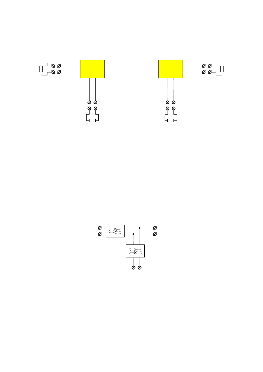
Functional diagram
The functional diagram for the splitter combination is given in figure 1.
(Central Office) or
TE-side
ADSL transceiver
ADSL transceiver
POTS
POTS
LE-side
(Optical network unit)
(Customer Premises)
"A"
"B"
POTS
LINE
ADSL
LINE
POTS
ADSL
Figure 1: Functional diagram of the DSL splitter configuration
The transfer functions between the different ports of the splitter can be understood as follows:
•
The transfer function from the POTS port to the LINE port and vice-versa is that of a low-pass filter.
•
A very high level isolation is required from the ADSL port to the POTS port and vice-versa to prevent
undesirable interaction between ADSL and any existing narrowband services.
•
The transfer function from the ADSL port to the LINE port and vice-versa is either that of a high-pass filter, or it
may be all pass in nature, in the case where the full high pass filter function is implemented in the DSL
transceiver.
POTS
PORT
ADSL
PORT
LINE
PORT
(Optional
High Pass)
Figure 2: Structure of the ADSL splitter filter
ETSI
ETSI TS 101 952-1-2 V1.1.1 (2002-05)
7
5
High pass filter options
The high pass filter, as referred to in the present document, is the series high pass filter that is located in the splitter unit.
It is distinct from the input high pass filter of the ADSL modem, which is located in the ADSL transceiver.
Reasons for including a series high pass filter in the LE splitter unit include the following:
•
safety to uncouple the POTS line from damage due to the ADSL service;
•
DC decoupling, to avoid "stealing" POTS service from the premises of an alternative operator;
•
POTS privacy, when ADSL is supplied by an alternative operator, to avoid "listening".
In the case of a CPE filter, the role of the series high pass filter is less important. It provides DC de-coupling between
the POTS and ADSL, and presents a more controlled impedance to the low pass filter at the ADSL port (e.g. it
potentially enables the POTS service to continue functioning in the case of a user short circuiting the ADSL port of the
splitter).
The high pass filter shall be one of the following options:
•
Option A: 0th order filter, i.e. no series high pass filter in the splitter unit;
•
Option B: 1st order filter made up of two blocking capacitors;
•
Option C: Higher order filter.
Implementation requirements for options B and C are given in clause 6.
Electrical requirements for each option are given in clause 7.
6
High Pass filter implementation
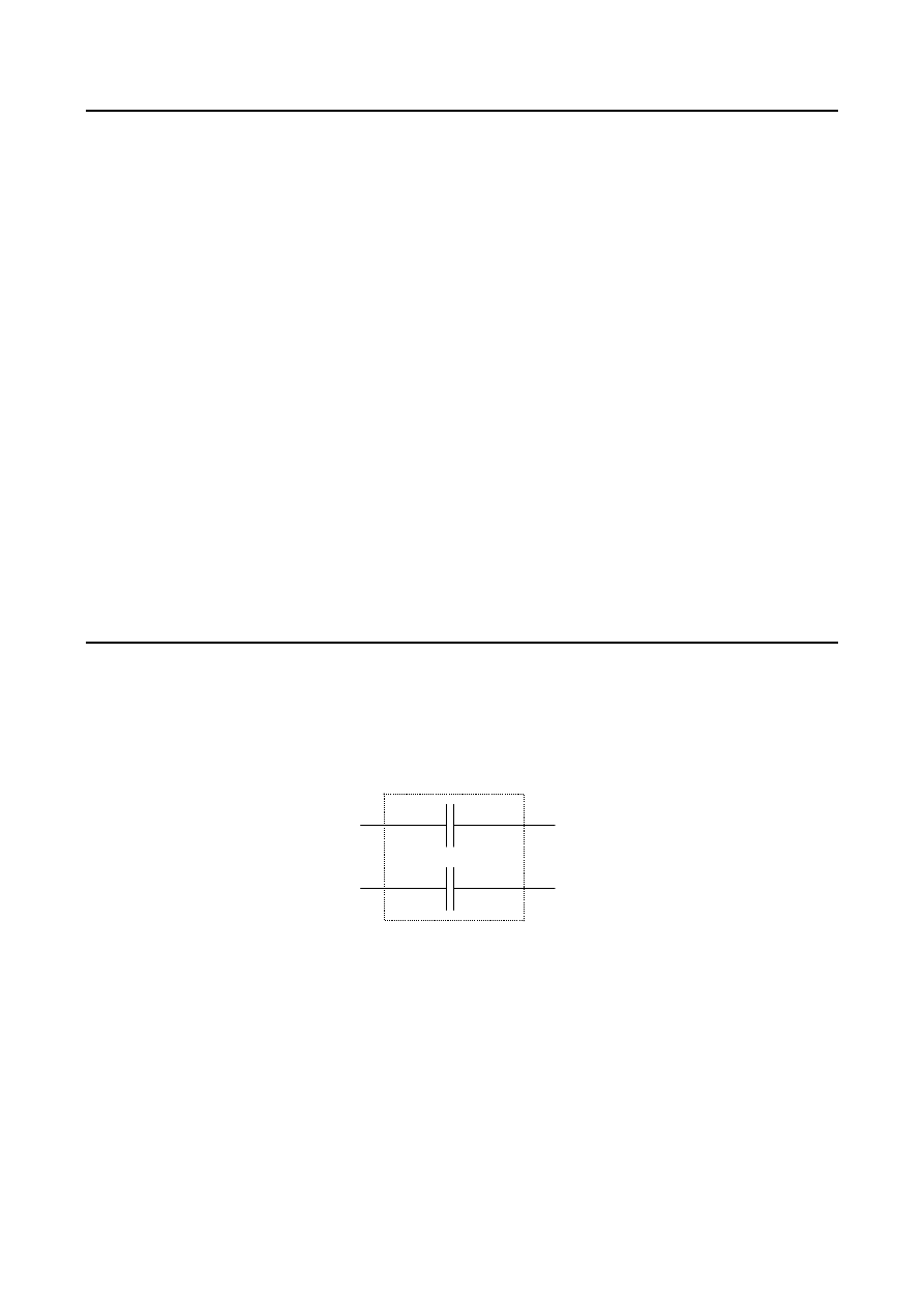
6.1
Option B: 1st order filter
Blocking capacitors C
B
= 120 nF, with C
B
as defined by figure 3, shall make up the 1
st
order high pass filter.
C
B
C
B
LINE
PORT
ADSL
PORT
Figure 3: Implementation of 1
st
order high pass filter
A tolerance of 5 % shall be allowed for the practical implementation of these capacitors. Each of these capacitors shall
retain their nominal value for DC voltages up to those present in the telephony network as defined in EN 300 001 [1].
ETSI
ETSI TS 101 952-1-2 V1.1.1 (2002-05)
8
6.2
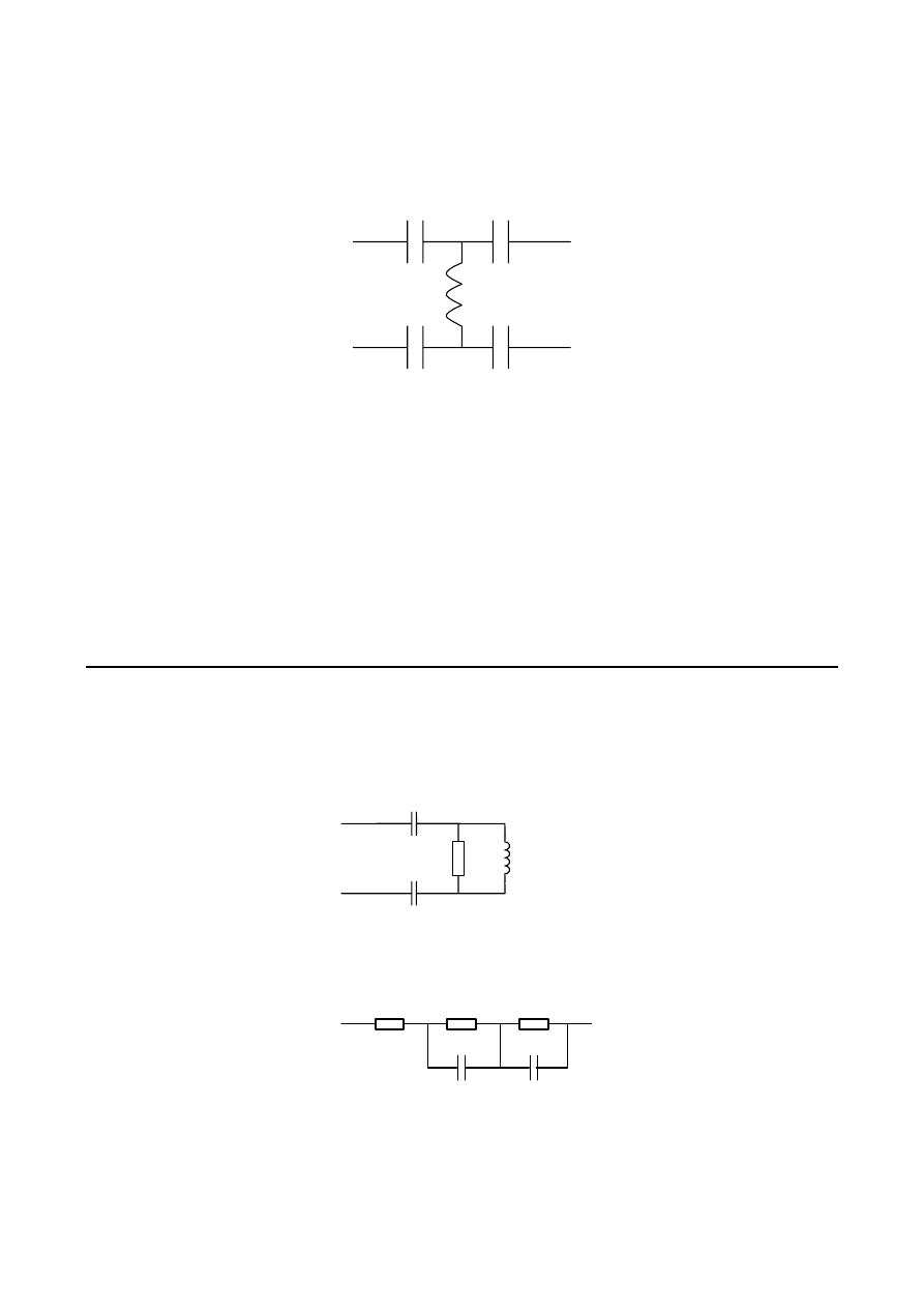
Option C: Higher order filter
The third order high pass filter as defined by figure 4 shall make up the Option C high pass filter.
LINE
PORT
ADSL
PORT
C
L
C
L
C
A
C
A
L
M
Figure 4: Implementation of 3
rd
order high pass filter
The following values for the electrical representation could be used: C
L
= 54 nF, C
A
= 90 nF, L
M
= 0,38 mH.
A tolerance of 5 % shall be allowed for the practical implementation of the capacitors. A tolerance of 7 % shall be
allowed for the inductor.
The impedance network presented in figure 4 is an electrical representation, rather than a circuit diagram. The
implementation shall present an equivalent impedance to that shown in figure 4, however derived.
NOTE:
The electrical representation given in figure 4 is considered to be a satisfactory implementation of the
higher order filter. Alternative implementation methods are for further study.
7
High Pass filter requirements
In the case where either option B or option C as described in clause 6 of the current document is present in the splitter
unit, the requirements of clause 7 shall be met. The impedances networks shown in figures 5 and 6 are used in some of
the test setups for these requirements.
100
Ω
100 nF
0,47 mH
100 nF
Figure 5: Schematic diagram of the Z
ADSL-M
150 nF
150
ohms
47 nF
750 ohms
120 ohms
Figure 6: Impedance Z
RHF
ETSI
ETSI TS 101 952-1-2 V1.1.1 (2002-05)
9
7.1
Insertion loss requirements
7.1.1
Insertion Loss requirements for options A and B
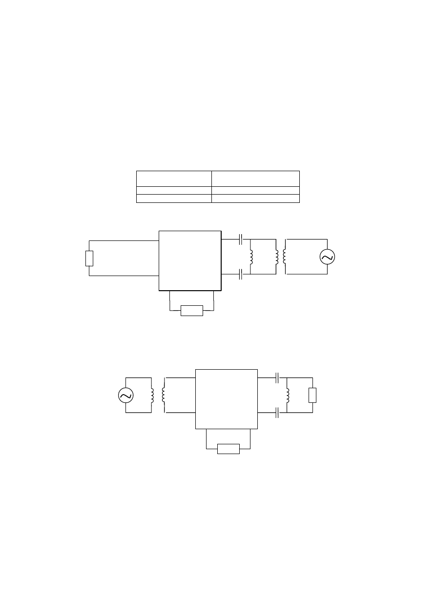
The insertion loss due to the insertion of the splitter (i.e. both the blocking capacitors and low pass filter in the case of
option B) between the LINE port and the ADSL port shall be as specified in table 1. Examples of valid test setups are
given in figures 7 and 8.
The insertion loss requirements of table 1 are to be met in the case where Z
POTS
of figure 7 is a short circuit, an open
circuit, and the nominal Z
RHF
impedance of figure 6.
Table 1: Insertion loss between LINE and ADSL port for ADSL/POTS splitters
Frequency range
Insertion loss between
LINE and ADSL port
32 kHz to 50 kHz
< 3 dB
50 kHz to 1 104 kHz
< 1 dB
100 nF
100 nF
0,47 mH
Signal
Source
(50
Ω
)
Balun
100
Ω
:50
Ω
100
Ω
Z
POTS
LINE
port
ADSL
port
POTS
port
Splitter Unit
Figure 7: Example ADSL to LINE insertion loss test setup
100 nF
100 nF
0,47 mH
LINE
port
ADSL
port
POTS
port
Splitter Unit
100
Ω
Signal
Source
(50
Ω
)
Balun
50
Ω
:100
Ω
Z
POTS
Figure 8: Example LINE to ADSL insertion loss test setup
7.1.2
Insertion Loss requirements for option C
The insertion loss due to the insertion of the splitter (i.e. both the high pass filter and low pass filter) between LINE port
and ADSL port shall be as specified in table 2. Examples of valid test setups are given in figures 7 and 8.
The insertion loss requirements of table 2 are to be met in the case where Z
POTS
of figures 7 and 8 is a short circuit, an
open circuit, and the nominal Z
RHF
impedance of figure 6.
ETSI
ETSI TS 101 952-1-2 V1.1.1 (2002-05)
10
Table 2: Insertion loss between LINE and ADSL port for ADSL/POTS splitters
Frequency range
Insertion loss between
LINE and ADSL port
50 kHz to 100 kHz
(for further study)
100 kHz to 1 104 kHz
(for further study)
7.2
Unbalance about earth requirements for options B and C
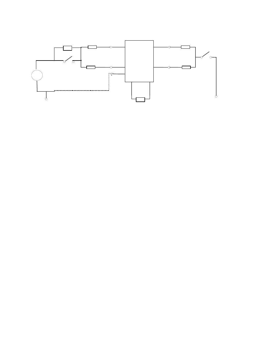
The basic test setup for measuring unbalance at the ADSL port is shown in figure 9. In the case of measuring at the
LINE port, the test setup of figure 9 is used, however with the ADSL and LINE terminations reversed. The test shall be
carried out for the combinations described in table 3. It should be noted that the source and measurement points are
always at the same port.
Table 3: Unbalance about earth, test setups
#Test setup
Source and
Measurement
S2
1
ADSL port
closed
2
ADSL port
open
3
LINE port
closed
The POTS port shall be terminated by a 600
Ω resistor for all unbalance tests described in the present document.
For each of the three test setups described above, the splitter shall meet the unbalance about earth requirements as
specified in table 4.
In the case of performing measurements at frequencies above 4 kHz, for reasons of practical testing a 150
Ω impedance
should be used in series with the longitudinal source (i.e. S1 in figure 9 should be open).
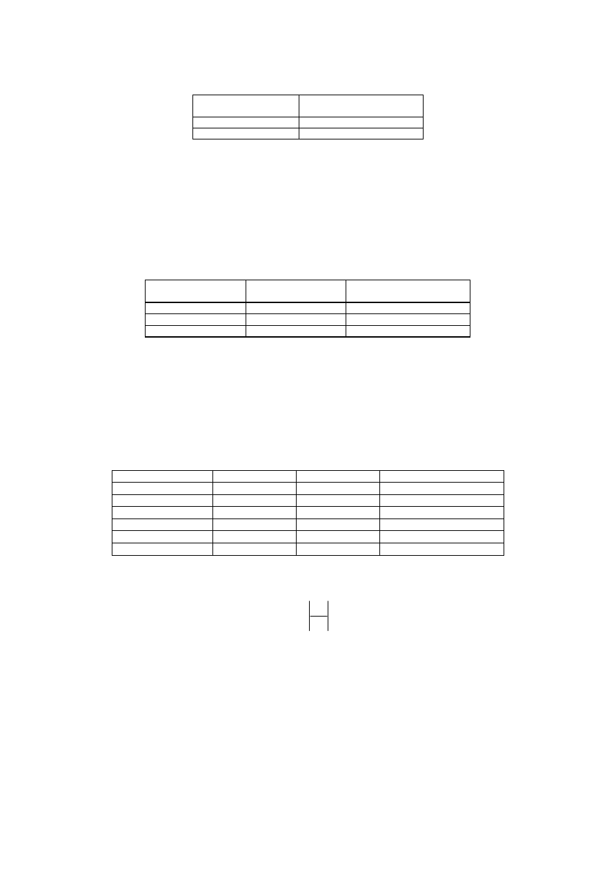
Table 4: Unbalance about earth, minimum values
Frequency range
State of S1
Value of R
Minimum Unbalance value
50 Hz to 600 Hz
closed
300
Ω
40 dB
600 Hz to 3 400 Hz
closed
300
Ω
46 dB
3 400 Hz to 4 000 Hz
closed
300
Ω
40 dB
4 kHz to 30 kHz
open
50
Ω
40 dB
30 kHz to 1 104 kHz
open
50
Ω
50 dB
1 104 kHz to 5 MHz
open
50
Ω
30 dB
The unbalance about earth is calculated by using the following equation:
( )
dB
U
U
20log
Unbalance
T
0
10
=
ETSI
ETSI TS 101 952-1-2 V1.1.1 (2002-05)
11
Earth point
R
R
S2
Line
port
ADSL
port
POTS
port
U
0
R
R
Splitter
Earth point
~
Earth
terminal
S1
150
Ω
600
Ω
U
T
+
_
NOTE 1: The dotted circuit is only used if the splitter has an earth terminal.
NOTE 2: The DC current feeding circuitry is not shown. Care should be taken that this circuitry is implemented in
such a way as not to have significant influence on the accuracy of the measurement.
NOTE 3: For resistances R an equivalent circuit according to ITU-T Recommendation O.9 [2] can be used.
Figure 9: Unbalance about earth test set-up
If the splitter has no earth terminal, the test should be performed while the splitter is placed on an earthed metal plate of
a sufficiently large size.

ETSI
ETSI TS 101 952-1-2 V1.1.1 (2002-05)
12
History
Document history
V1.1.1
May 2002
Publication
Document Outline
- Intellectual Property Rights
- Foreword
- 1 Scope
- 2 References
- 3 Abbreviations
- 4 General functional description of ADSL/POTS splitters
- 5 High pass filter options
- 6 High Pass filter implementation
- 7 High Pass filter requirements
- History
Wyszukiwarka
Podobne podstrony:
ADSL High Speed Internetzugang
filtr górnoprzepustowy
Filtr górnoprzepustowy i dolnoprzepustowy RC , prostowniki i przetworniki oraz stabilizator
FILTR gornoprzepustowy
Cwiczenie 4 Filtr dolno i gornoprzepustowy, Ćwiczenie 4
Filtr górnoprzepustowy 1
filtr gornoprzepustowy (2)
filtr górnoprzepustowy
Filtr górnoprzepustowy 2
Filtr (elektronika)
high key
CEREBRAL VENTICULAR ASYMMETRY IN SCHIZOPHRENIA A HIGH RESOLUTION 3D MR IMAGING STUDY
1 high and popular culture
Hello Kitty, Monster High itd
Filtr paliwa seria K
23 299 318 Optimizing Microstructure for High Toughness Cold Work Steels
Castles & Crusades Wilderlands of High Adventure
więcej podobnych podstron