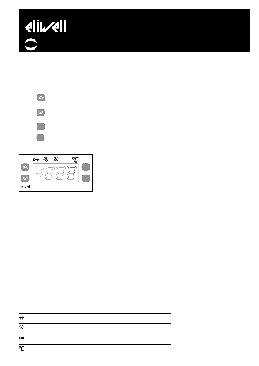
USER INTERFACE
The user has a display and four keys for
controlling status and programming of the
instrument.
KEYS AND MENUS
UP key
Scrolls through the menu items
Increases the values
Activates manual defrost
DOWN key
Scrolls through the menu items
Decreases the values
Programmable by parameter
fnc key
ESC function (exit)
Programmable by parameter
set key
Accesses the setpoint
Accesses the menus
Confirms the commands
Displaying the alarms (if present)
At start-up the instrument performs a
Lamp Test; for few seconds the display and
the leds blink, in order to verify their
integrity and correct operation. The instru-
ment has two main menus: the “Machine
Status” and “Programming” menu.
ACCESSING AND USING MENUS
Resources are arranged in a menu, which
can be accessed by pressing and quickly
releasing the “set” key (“Machine Status”
menu) or by holding down the “set” key
for more than 5 seconds (“Programming”
menu).
To access the contents of each folder, indi-
cated by the relevant label, just press the
“set” key once.
You can now scroll through the contents
of each folder, modify it or use its func-
tions.
If you do not use the keyboard for over
15 seconds (time-out) or if you press the
“fnc” key once, the last value shown on
the display is confirmed and you return to
the previous screen mask.
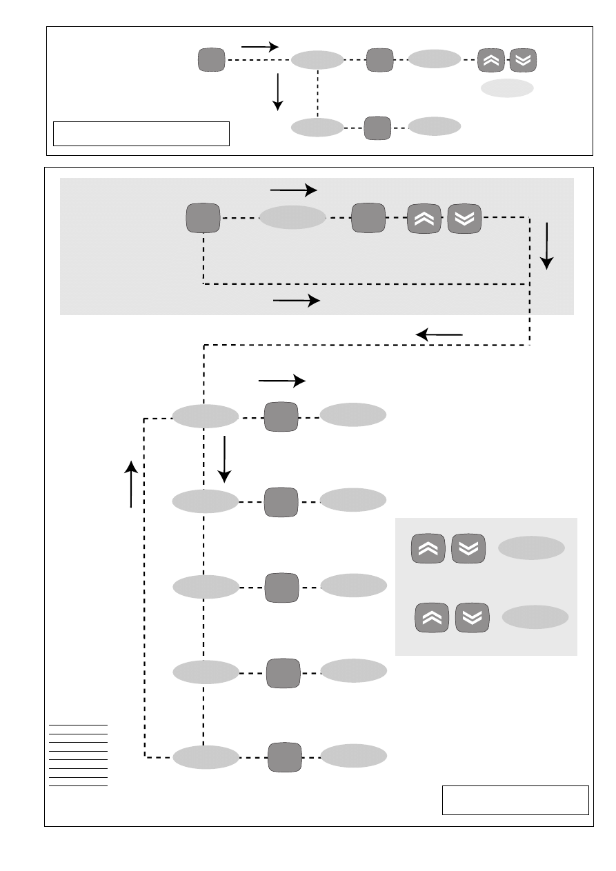
MACHINE STATUS MENU
(See Machine Status Menu)
To access the “Machine Status” menu
Press and quickly release the “set” key.
If alarms are not present, the label “SEt”
appears. By using the “UP” and “DOWN”
keys you can scroll through the other fold-
ers in the menu:
-Pb1: probe 1 value folder;
-SEt: Setpoint setting folder.
Set Setting
Access the “Machine Status” menu by
pressing and quickly releasing the “set”
key. The label of the “Set” folder appears.
To display the Setpoint value press the
“set” key again.
The value appears on the display.
To change the Setpoint value, use the “UP”
and “DOWN” keys within 15 seconds.
If the parameter is LOC = y the Setpoint
cannot be changed.
Displaying Probes
By pressing the “set” key when the appro-
priate label appears, the value of the
probe associated to it is displayed.
PROGRAMMING MENU
(See Programming Menu)
To enter the “Programming” menu, press
the “set” key for more than 5 seconds.
If specified, the access PASSWORD will be
requested, (parameter “PA1”), and (if the
password is correct) the label of the first
folder will follow.
To scroll through the other folders, use
the “UP” and “DOWN” keys.
If the password is wrong, the display will
show the PA1 label again.
To enter the folder, press “set”. The label
of the first visible parameter appears. To
scroll through the other parameters, use
the “UP” and “DOWN” keys; to change the
parameter, press and release “set”, then
set the desired value using the “UP” and
“DOWN” keys, and confirm with the “set”
key to move to the next parameter.
PLEASE NOTE: It is suggested to switch-
off and switch-on again the instrument
everytime it is changed the configuration
of the parameters: this prevents malfunc-
tioning on regulation and delay time
occuring.
PASSWORD
The password “PA1” allows access to pro-
gramming parameters. In the standard
configuration password is not present.
To enable (value≠0) and assign it the
desired value, access the “Programming”
menu, within the folder with the “diS”
label. If password is enabled, you will see
it at the entrance of the “Programming”
menu (see the “Programming Menu“ sec-
tion).
MANUAL ACTIVATION OF THE
DEFROSTING CYCLE
To manually activate the defrosting cycle,
press the “UP” key for 5 seconds.
COPY CARD
The Copy Card is an accessory connected
to the TTL serial port which allows pro-
gramming quickly the instrument parame-
ters. The operation is performed as fol-
lows:
Format
This command allows copy card format-
ting, an operation recommended in case
of first use.
Warning: if the copy card has been pro-
grammed, using the “Fr” the data entered
are erased. This operation cannot be can-
celled.
Upload
This operation loads the programming
parameters from the instrument.
Download
This operation downloads to the instru-
ment the programming parameters.
The operations are performed accessing
the folder identified by the “FPr” label and
selecting, according to the case, “UL”, “dL”
or “Fr” commands; the operation is con-
firmed by pressing the “set” key. If the
operation is successful an “y” is displayed,
on the contrary, if it fails a “n” will be dis-
played.
NOTE:
• UPLOAD: instrument --> Copy Card
• DOWNLOAD: Copy Card --> instru-
ment.
ID 961
electronic controllers for refrigerating units
fnc
set
LED
Position
Related Function
Status
Compressor or relay 1
ON when the compressor is started up; blinking in case of delay,
protection or blocked enabling
Defrost
ON when defrosting; blinking in case of manual
enabling
Alarm
ON when the alarm is enabled; blinking when the alarm is silenced
Setpoint
On for setting Setpoint
set
f nc
ID961
cod. 9IS42060
rel. 1/05
GB

KEYBOARD LOCKING
The instrument includes a facility for dis-
abling the keyboard, by programming the
“Loc” parameter (see folder with “diS”
label). If the keyboard is locked, you can
still access the programming menu by
pressing the “set” key.
The Setpoint can also be viewed.
DIAGNOSTICS
The alarm condition is always signalled by
the buzzer (if present) and by the led of
the alarm icon
The alarm signal produced by a faulty
thermostat probe (probe 1) is shown as E1
on the instrument display.
When the sensor detects an error condi-
tion:
• the code E1 is displayed
• the compressor is activated as indicated
by the "On" and "Off" parameters if pro-
grammed for the duty cycle or:
INSTALLATION
The instrument is designed for panel
mounting. Make a hole of 29x71 mm,
insert the instrument and fix it using the
brackets provided. Do not mount the
instrument in humid and/or dirty places; it
is suitable for use in ordinary polluted
places. Ventilate the place in proximity to
the instrument colling slits.
ELECTRICAL
WIRING
Attention! Never work on electrical
connections when the machine is
switched on.
The instrument is equipped with screw ter-
minal boards for connection of electrical
cables with a diameter of 2.5 mm
2
(one
conductor only per terminal for power
connections).
For the capacity of the terminals, see the
label on the instrument.
The relay contacts are voltage free. Do not
exceed the maximum current allowed; in
case of higher loads, use an appropriate
contactor. Make sure the power supply
voltage complies with the one required by
the instrument.
In 12V versions the power supply must be
provided by a security transformer with
the protection of a delayed 250 mA fuse.
Probes have no connection polarity and
can be extended using a regular bipolar
cable (note that the extension of the
probes affects the EMC electromagnetic
compatibility of the instrument: pay
extreme attention to wiring).
Probe cables, power supply cables and the
TTL serial cables should be distant from
power cables.
CONDITIONS OF USE
PERMITTED USE
For safety reasons the instrument must be
installed and used according to the
instruction provided and in particular,
under normal conditions, parts bearing
dangerous voltage levels must not be
accessible.
The device must be adequately protected
from water and dust as per the application
and must also only be accessible via the
use of tools (with the exception of the
frontlet).
The device is ideally suited for use on
household appliances and/or similar refrig-
eration equipment and has been tested
with regard to the aspects concerning
European reference standards on safety. It
is classified as follows:
• according to its manufacture: as an auto-
matic electronic control device to be
incorporated by independent mounting;
• according to its automatic operating fea-
tures: as a 1 B-type operated control type;
• as a Class A device in relation to the cat-
egory and structure of the software
UNPERMITTED USE
Any other use other than that permitted is
de facto prohibited. It should be noted
that the relay contacts provided are of a
practical type and therefore subject to
fault. Any protection devices required by
product standards or dictated by common
sense due to obvious safety reasons should
be applied externally.
LIABILITY AND RESIDUAL
RISKS
Eliwell & Controlli s.r.l. shall not be liable
for any damages deriving from:
- installation/use other than that pre-
scribed and, in particular, that which does
not comply with safety standards anticipat-
ed by regulations and/or those given here-
in;
- use on boards which do not guarantee
adequate protection against electric shock,
water or dust under the conditions of
assembly applied;
- use on boards which allow access to dan-
gerous parts without the use of tools;
- tampering with and/or alteration of the
products;
- installation/use on boards that do not
comply with the standards and regulations
in force.
TECHNICAL DATA
Frontal panel protection: IP65.
Casing: plastic body in resin type
PC+ABS UL94 V-0, inspection window in
polycarbonate, buttons in thermoplastic
resin.
Dimensions: frontal panel 74x32 mm,
depth 60 mm.
Installation: on panel, with drilling tem-
plate 71x29 mm (+0.2/–0.1 mm).
Use temperature: –5…55 °C.
Storage temperature.: –30…85 °C.
Use environment humidity: 10…90 % RH
(not condensing).
Storage environment humidity: 10…90% RH
(not condensing).
Viewing range: –50…99 without decimal
point on 2 digit + mark display.
Analog inputs: one PTC or NTC input
(selectable through parameter H00*).
Serial: TTL for connection to Copy Card.
Digital outputs: 1 relay contact
SPDT 8(3)A 250V
a.
Measuring range: from –50 to 99 °C.
Accuracy: 0.5% better than end scale + 1
digit.
Resolution: 1°C.
Consumption:
• model 230V: 3 VA max.
• model 12V: 1,5 VA max.
Power supply: 12 V
a/c ±10% or 230Va
±10% 50/60 Hz.
MODEL 16A 2hp
Digital output: 1 N.O. relay SPST 16A 2hp
250V
A.
Consumption: 3 VA max.
Power supply: 230 V
a ±10% 50/60 Hz.
*NOTE 1: Switch off and switch on
again the instrument after changing
the input type NTC/PTC (par. H00)
NOTE 2: check the power supply speci-
fied on the instrument label; for relay
and power supply capacities, contact
the Sales Office).
ID 961
2/5
DISPLAY
E1
ERROR
Thermostat probe fault
Error table
Ont
0
0
>0
>0
Oft
0
>0
0
>0
Compressor output
OFF
OFF
ON
dc
PLEASE NOTE: The technical data
included in this document, related to
measurement (range, accuracy, resolu-
tion, etc.) refer to the instrument
itself, and not to its equipment such as,
for example, sensors.
This means, for example, that sensor(s)
error(s) shall be added to the instru-
ment’s one.

ID 961
3/5
Tab. 1
Parameter Table
PAR.
diF
HSE
LSE
Ont (1)
OFt (1)
dOn
dOF
dbi
OdO
dit
dCt
dOH
dEt
dPO
LOC
PA1
CA1
ddL
dro
H00 (*)
reL
tAb
UL
dL
Fr
(1) see Duty Cycle Diagram
* DEFAULT column: for H00 parameter default is depending on model
* NOTE 1: Switch off and switch on again the instrument after changing the input type NTC/PTC (par. H00)
** VALUE column: to be filled manually, with customized settings (if different from the default value).
*** LEVEL column: indicates the level of visibility of parameters accessible by PASSWORD (see the related paragraph)
DESCRIPTION
COMPRESSOR REGULATOR (folder with “CP” label)
diFferential. Relay compressor tripping differential. The compressor stops on reaching the
Setpoint value (as indicated by the adjustment probe), and restarts at temperature value
equal to the Setpoint plus the value of the differential.
Note: the value 0 cannot be assumed.
Higher SEt. Maximum possible setpoint value.
Lower SEt. Minimum possible setpoint value.
COMPRESSOR PROTECTIVE DEVICE (folder with “CP” label)
On time (compressor). Compressor activation time in the event of faulty probe. If set to
“1” with Oft at “0” the compressor is always on, while at Oft >0 it functions always
in duty cycle mode.
OFF time (compressor). Compressor in disabled state time in the event of a faulty probe.
If set to “1” with Ont at “0” the compressor is always off, while at Ont >0
it functions always in duty cycle mode.
delay (at) On compressor. Delay time in activating the compressor relay after switch-on
of instrument
delay (after power) OFF. Delay after switch off; the indicated time must elapse between
switch-off of the compressor relay and the successive switch-on.
delay between power-on. Delay between switch-ons; the indicated time must elapse
between two successive switch-ons of the compressor.
delay Output (from power) On. Delay time in activating the outputs after switch-on of
the instrument or after a power failure.
DEFROSTING REGULATOR (folder with “dEF” label
defrost interval time. Interval between the start of two successive defrosting operations.
defrost Counting type. Selection of count mode for the defrosting interval.
0 = compressor operating hours (DIGIFROST® method);
1 = Real Time – appliance operating time;
2 = compressor stop.
defrost Offset Hour. Start-of-defrosting delay time from start up
of instrument.
defrost Endurance time. Defrosting time-out; determines duration of
defrosting.
defrost (at) Power On. Determines if at the start-up the instrument must enter defrosting
(if the temperature measured allows this operation).
y = yes; n = no.
DISPLAY (folder with “diS” label)
(keyboard) LOCk. Keyboard locking. However, you can enter parameter programming
modify them along with the status of this parameter in order to allow keyboard locking.
y = yes; n = no
PAssword 1. When enabled (value other than 0) it constitutes the access key for
level 1 parameters.
CAlibration 1. Positive or negative temperature value added to the value read by probe 1.
defrost display Lock. Viewing mode during defrosting.
0 = shows the temperature read by the thermostat probe;
1 = locks the reading on the temperature value read by thermostat probe when
defrosting starts, and until the next time the Setpoint value is reached;
2 = displays the label “deF” during defrosting, and until the next time the
Setpoint value is reached.
display read-out. Select °C or °F for displaying the temperature read by the thermostat
probe. 0 = °C, 1 = °F.
CONFIGURATION (folder with “CnF” label)
Probe type selection, PTC or NTC. 0 = PTC; 1 = NTC.
reLease firmware. Device version: read only parameter.
tAble of parameters. Reserved: read only parameter.
COPY CARD (folder with “Fpr”label)
Up load. Programming parameter transfer from instrument to Copy Card.
Down load. Programming parameter transfer from Copy Card to instrument
Format. Erasing all data in the copy card.
PLEASE NOTE: using “Fr” parameter (copy card formatting) the data within the
copy card will be lost permenently. The operation cannot be cancelled.
DEFAULT*
2
99
-50
0
1
0
0
0
0
6h
1
0
30min
n
n
0
0
1
0
0/1
/
/
/
/
/
RANGE
1...30
LSE..302
-55...HSE
0...250
0...250
0...250
0...250
0...250
0...250
0...250
0/1/2
0...59
1...250
n/y
n/y
0...250
-12...12
0/1/2
0/1
0/1
/
/
/
/
/
VALUE**
LEVEL***
1
1
1
1
1
1
1
1
1
1
1
1
1
1
1
1
1
1
1
1
1
1
1
1
1
U.M.
°C/°F
°C/°F
°C/°F
min
min
sec
min
min
min
hours
flag
min
min
flag
flag
num
°C/°F
flag
flag
flag
/
/
/
/
/
ID 961
4/5
CP
dEF
set
level 1 par
level 1 par
set
set
PA1≠0
set
set PA1 value
diS
CnF
Fpr
level 1 par
level 1 par
level 1 par
set
set
set
level 1
change
par value
scroll
parameters
press for 5 sec
Programming Menu Diagram
PARAMETERS
folders level 1
CP
dEF
diS
CnF
FPr
Pb1
SEt
Pb1 value
SEt value
set
set
set
change
SEt value
press and release
(single press)
Machine Status Menu Diagram
ID 961
5/5
Eliwell & Controlli s.r.l.
Via dell'Industria, 15 Zona Industriale Paludi
32010 Pieve d'Alpago (BL) ITALY
Telephone +39 0437 986111
Facsimile +39 0437 989066
Internet http://www.eliwell.it
Technical Customer Support:
Email: techsuppeliwell@invensys.com
Telephone +39 0437 986300
Invensys Controls Europe
Part of the Invensys Group
1/2005 eng
cod. 9IS42060
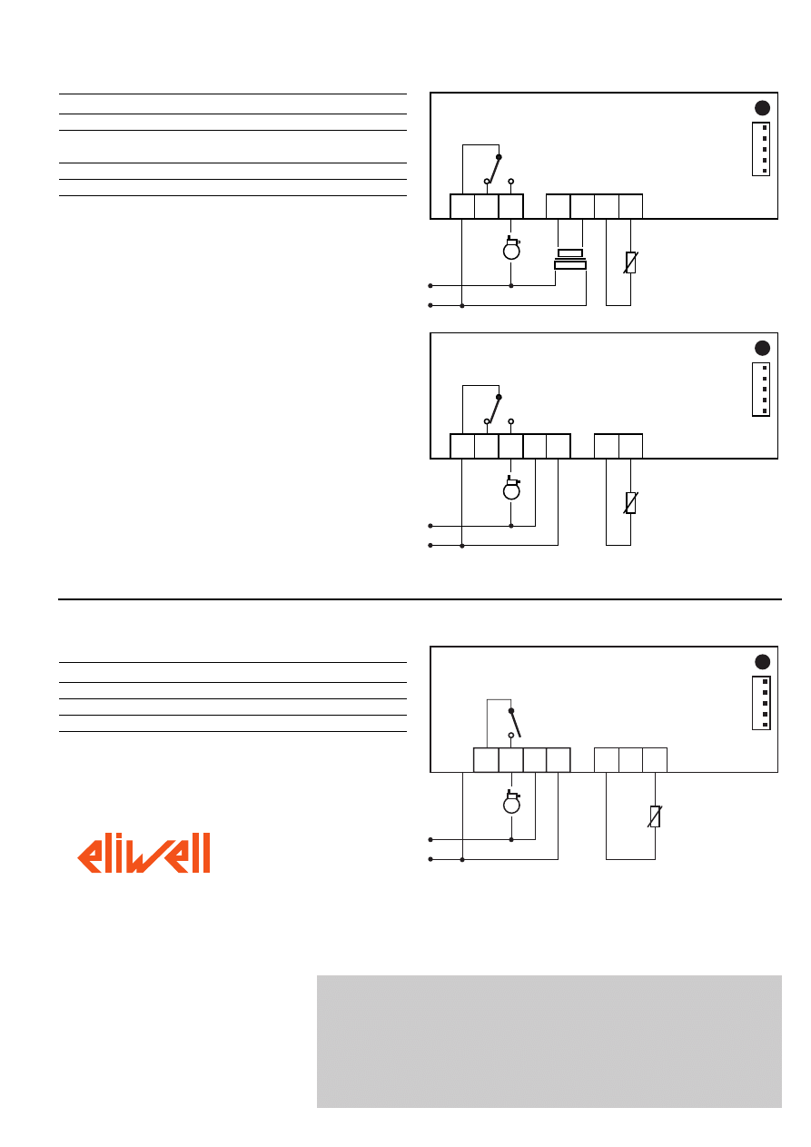
Wiring diagram
1 2 3
6 7 8 9
ID 961 - 12 V
A
TERMINALS (12 and 230V)
1 - 2
N.C. compressor relay
1 - 3
N.O. compressor relay
6 - 7
Power supply • model 230V: 3 VA max.
• model 12V: 1,5 VA max.
8 - 10
Probe 1 input (thermostat)
A
TTL input for Copy Card
NOTE:
• User Default Settings
• For relay capacities check on the instrument label.
In the diagram it is shown relays with 8(3) 1/2 hp 250V
capability and 12/230V supply
1 2 3 6 7
8 9
ID 961 - 230 V
A
DISCLAIMER
This manual and its contents remain the sole property of Eliwell & Controlli s.r.l., and
shall not be reproduced or distributed without authorization. Although great care has
been exercised in the preparation of this document, Eliwell & Controlli s.r.l., its
employees or its vendors, cannot accept any liability whatsoever connected with its
use. Eliwell & Controlli s.r.l. reserves the right to make any changes or improvements
without prior notice.
MODEL 16A 2hp
TERMINALS
4 - 5
N.O. compressor relay output
6 - 7
Power supply
8 - 10
Probe 1 input (thermostat)
A
TTL input for Copy Card
4 5 6 7
8 9
ID 961 - 230 V
A
10
16A 2hp
Wyszukiwarka
Podobne podstrony:
ID 961
961 367 id 48732 Nieznany (2)
13 ZMIANY WSTECZNE (2)id 14517 ppt
!!! ETAPY CYKLU PROJEKTU !!!id 455 ppt
2 Podstawowe definicje (2)id 19609 ppt
2 Realizacja pracy licencjackiej rozdziałmetodologiczny (1)id 19659 ppt
02 MAKROEKONOMIA(2)id 3669 ppt
WSPÓŁCZESNE ID ED
11b Azotowanie i nawęglanie (PPTminimizer)id 13076 ppt
1 Wprowadzenie do psychologii pracy (14)id 10045 ppt
12a Równowaga ciecz para w układach dwuskładnikowych (a)id 14224 ppt
2 Urazy zębów u pacjentów dorosłych klasyfikacje (2)id 19701 ppt
1 Choroby układu pokarmowego(1)id 9116 ppt
Abolicja podatkowa id 50334 Nieznany (2)
więcej podobnych podstron