2Channel + Microphone Stereo Mixer
A lot of friends me asked to draw a more shrunk circuit 2-ch mixer, which will contain also, operation CROSSFADER. The circuits can be modified and
added also other channels, repeating basic that I give. It can are added channels stereo PHONO/line or even channels microphone with proportional
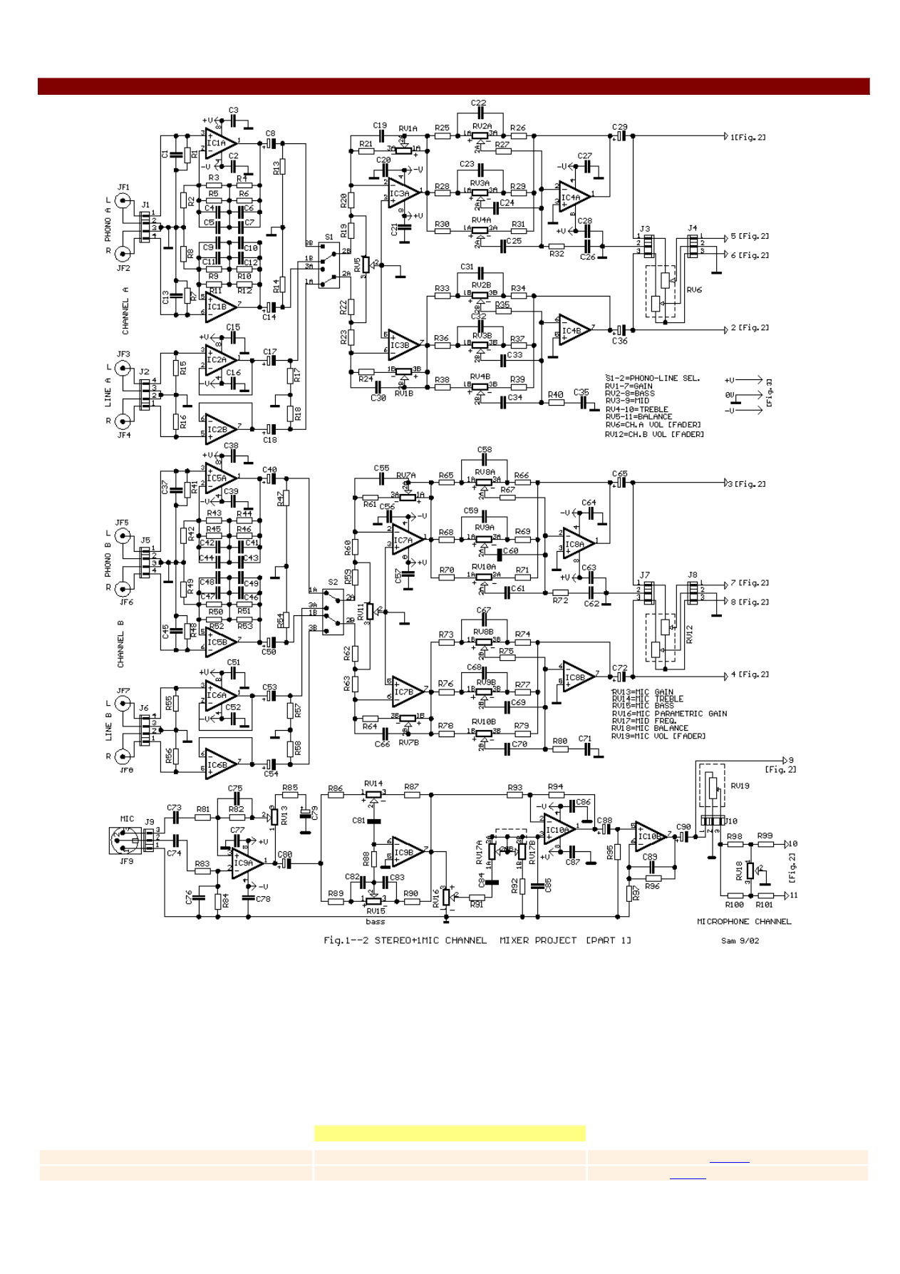
modification of next stages. In the Fig.1 exist the input circuits of two channels and input of microphone channel. The two basic channels she is same
between them. Thus that its go for a channel, the he is also go for the other. In each stereo channel exist two inputs, classic stereo input PHONO that
is practical a correction filter RIAA and concerns the signal amplification of sound that emanates from the classic reproduction heads of classic disks LP.
Exist also a stereo input of LINE
high level
for signals that emanate from CD players, Tuners, DVD, etc. The exits of this two stages are selected
with switch S1 or S2 and they are applied in the next stage which is constituted from adder IC3. Here is regulated the BALANCE with the RV5 and GAIN
with the RV1. In the next stage round the IC4 exist a classic 3-band regulation of tone circuit, the regulation of which becomes with the RV2-3-4. The
exit of IC4 drive the RV6 that is at preference pontesometer [FADER]. By points 1-2-5-6 the signals connected to next stage [Fig.2]. In the Fig.1 exist
also the microphone input, which is in electronic Balance connection, round the IC9A. Here exist the regulation of GAIN with the RV13. It follows a stage
of tone two-band regulation, round the IC9B and a stage of parametric regulation of mid band with RV16 [Gain] and RV17 [Frequency Band]. With the
RV19 we regulate VOLUME [FADER] and with the RV18 we regulate the BALANCE. By points 9-10-11 the signal is connected to the corresponding points
that are found in the Fig. 2.
Part List
[Fig.1]
R1-7-15-16-41-48-55-56=47 Kohms
C1-13-37-45=150pF mylar-ceramic
IC1-5-9-10=NE5532-
LM833
R2-8-42-49=150 ohms
C2-3-15-16-20-21-27-28-38-39=47nF
IC2-3-4-67-8=
TL072
R3-5-9-11-43-45-50-52=180 Kohms
C4-5-9-11-42-44-47-48=18nF
RV1-7= 22 Kohms Log. pot.*
R4-6-10-12-44-46-51-53=15 Kohms
C6-10-41-46=3.9nF
RV2-3-8-9=2X100 Kohms Lin. pot.*
R13-14-17-18-47-54-57-58-95=100 Kohms
C7-12-43-49-82-83=5.6nF
RV4-10=2X470 Kohms Lin. pot.*
R19-22-59-62-98-100=4.7 Kohms
C8-14-17-18-40-50-53-54-88=10uF 16V
RV5-11-18=10 Kohms Lin. pot.*
R20-23-60-63-21-24-61-64=10 Kohms
C19-30-55-66-89=22pF
RV6-12=2X22 Kohms Log. pot. 45mm Slider
[FADER]
R25-26-33-34-65-66-70-71=10 Kohms
C22-31-58-67=47nF
RV13=10 Kohms Log. pot.*
R27-35-67-73-74-75-78-79-96=10 Kohms
C23-32-59-68-25-34-61-70-85=4.7nF
RV14-15-16=47 Kohms Lin. pot.*
R28-29-36-37-68-69-76-77=3.3 Kohms
C24-33-60-69=22nF
RV17=2X100 Kohms Log.pot.*
R30-31-38-39-70-71-78-79=1.8 Kohms
C26-35-62-71=1.2nF
RV19=10 Kohms Log. pot. 45mm Slider [FADER]
R32-40-72-80=330 ohms
C29-36-65-72-80-90=10uF 16V
J1-2-5-6=4pin conn. 2.54mm pin step
R81-83=2.2 Kohms
C56-57-63-64=47nF
J3-4-7-8-9-10=3pin conn. 2.54mm pin step
R82-97=6.8 Kohms
C73-74=1uF 100V MKT
Jf1....8=RCA female Jack
R84-88-93-94=22 Kohms
C75-76=68pF ceramic or mylar
JF9=3pin XLR male
R85=100 ohms
C77-78-86-87=47nF
R86-87=2.7 Kohms
C79=47uF 16V
R89-90=5.6 Kohms
C81=2.2nF
*ALPS or PIHER type Potentiometer
R91-92=3.9 Kohms
C84=10nF
All the Resistors is 1/4W 1% metal film
R99-101=10 Kohms
S1-2=2X2 0N/ON SW
All the [nF] capacitors is 63-100v 5% MKT
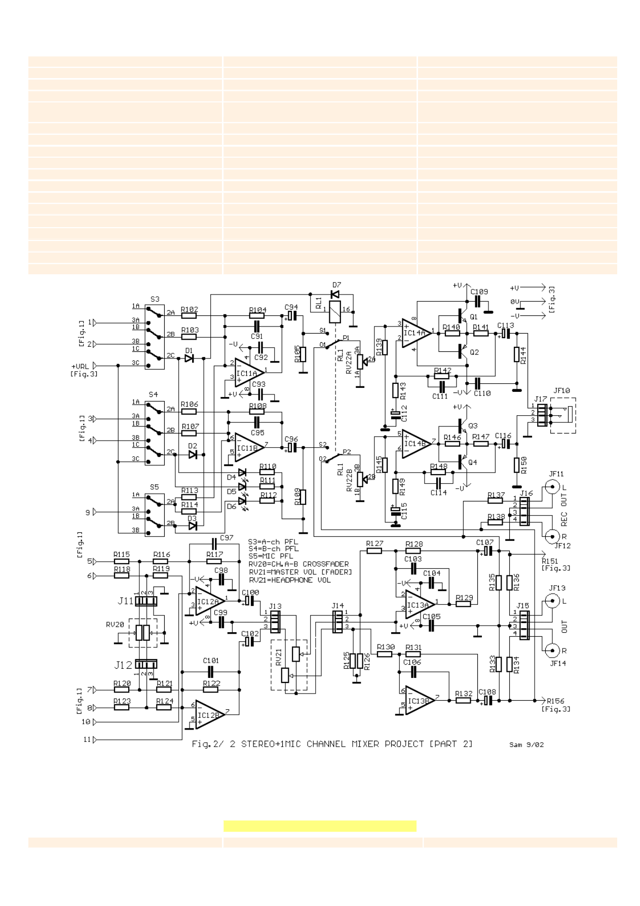
In the Fig.2 abut the various signals that emanate from the Fig.1. Switches S3-4-5 execute the operation of pre-Fader-listen [PFL] of proportional
channels. If some switch functions then turns on corresponding diode led D4-5-6. Simultaneous turn-on the relay RL1 disconnect the program in the
headphone and supply with the PFL signal. Round the IC14 exist the amplifier circuits of headphone drive. Round the IC12 exist the addition circuit of the
signals from the two channels and the mic channel, as well the RV20 which function as CROSSFADER between the two stereo channels. The RV21 is final
MASTER VOLUME [FADER] and adjust the final percentage of signal to the output. This role undertake the IC13 that has the leading possibility via the
outputs Jf13-14 a power amplifier, simultaneously from the exits Jf11-12 we can take signal for recording.
Part List
[Fig.2]
R102-103-106-107-113-114=10 Kohms
RV20=2X22 Kohms Log. pot. 45mm Slider
Q2-4=BD140
[FADER]
R104-108-117-122-125-126=22 Kohms
RV21=2X10 Kohms Log. pot. 45mm Slider
[FADER]
S3-4=3X2 PDT 0N/ON SW
R105-109=1 Mohms
RV22=2X10 Kohms Log. pot.*
S5=2X2 PDT ON/ON SW
R110-111-112=1 Kohms
C91-95-97-101-103-106-111-114=22pF
RL1=12V Relay 2X2 SW
R115-118-120-123-127=10 Kohms
C92-93-98-99-104-105-109-110=47nF
JF10=Jack female stereo 6.3mm
R116-119-121-124-130=10 Kohms
C94-96-100-102=10uF 16V
JF11....14=RCA female Jack
R128-131=27 Kohms
C107-108-113-116=470uF 25V
J11....14-17=3pin conn. 2.54mm pin ste
R129-132-137-138-140-146=100 ohms
C112-115=47uF 16V
J16-17=4pin conn. 2.54mm pin step
R133-135-139-145=100 Kohms
IC11-12=TL072
RV20=2X47 Kohms Lin. Slider [FADER]*
R134-136=47 ohms
IC13-14=NE5532 - LM833
RV21=2X10 Kohms Log. Slider [FADER]*
R141-147=10 ohms
D1-2-3=1N4002
R142-148=4.7 Kohms
D4-5-6=LED 3 or 5mm RED
*ALPS or PIHER type Potentiometer
R143-149=820 ohms
D7=1N4148
All the Resistors is 1/4W 1% metal film
R144-150=47 Kohms
Q1-3=BD139
All the [nF] capacitors is 63-100v 5% MKT
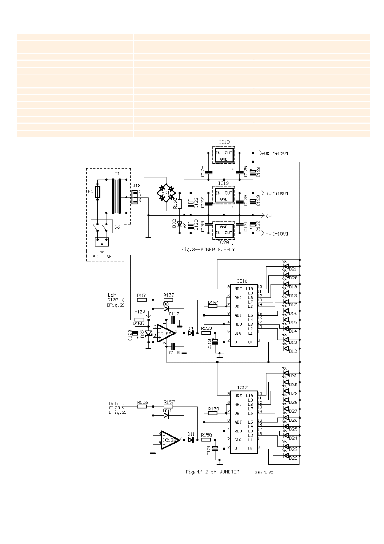
In the Fig.3 exist a classic supply circuit and stabilization of various voltages that needs the various circuits of mixer as +/-15V for the Audio department
and + 12V for the RL1 and VU meter supplying. The regulators IC18-19-20 good its they are placed on small heatsinks. Transformer T1 its placed in
a separate box, far from the remainder circuit, so that is not created problem of influence of rests circuits, from noise, unless its toroidal. In the Fig.4 is
found the indication circuit of level. This becomes with two classic circuits round the IC16-17 that drive the diodes Led D12 ..D31, that portrays the
level in steps of 3dB. The IC15 functions as precision rectifier.
Part List
[Fig.3-4]
R151-152-156-157=10 Kohms
BR1= 80V/3A BRIDGE RECTIFIER
IC20=7915 on Heatsink
R153-154-155-158-159=1 Kohms
D8-9-10-11=1N4148
T1=230V//2X15Vac >30VA
R160=2.7 Kohms
D12.......31-32=RED LED
F1=500mA SLOW BLOW FUSE
C117-118-124-125-127-128-130-131=100nF
D33=12V 0.5W ZENER
S6=2X2 ON-OFF SWITCH
C119-121=1uF 25V
IC15=
TL072
J18=3pin conn. 3.96mm pin step
C120=10uF 25V
IC16-17=LM3516
C122-123=4700uF 40V
IC18=7812 on Heatsink
All the Resistors is 1/4W 1% metal film
C126-129-132=19uF 25V
IC19=7815 on Heatsink
All the [nF] capacitors is 63-100v 5% MKT
SPECIFICATIONS
PHONO INPUT [Unbalaced RCA]
Sensitivity
2.5mV rms
Impedance
47K//150pF
LINE INPUT [Unbalaced RCA]
Sensitivity
1V rms
Impedance
47K
Gain
X1 until X3
3-band EQ
50HZ, 1KHZ, 10KHZ
[±18dB/oct]
MIC INPUT [Balanced XLR]
Sensitivity
-56dB
Impedance
2K
Gain
36dB
EQ. Section
High
±18db at 20KHZ
Mid. Freq.
200HZ - 6KHZ
Mid. Gain
±15db
Low
±18db at 20HZ
HEADPHONE OUT
impedance
100 ohms min.
FREQUENCY RESPONSE
20HZ-20KHZ -2dB
DISTROTION T.H.D
0.01% A 1KHZ
OUTPUT LEVEL
+4db Typ.
Block Diagram
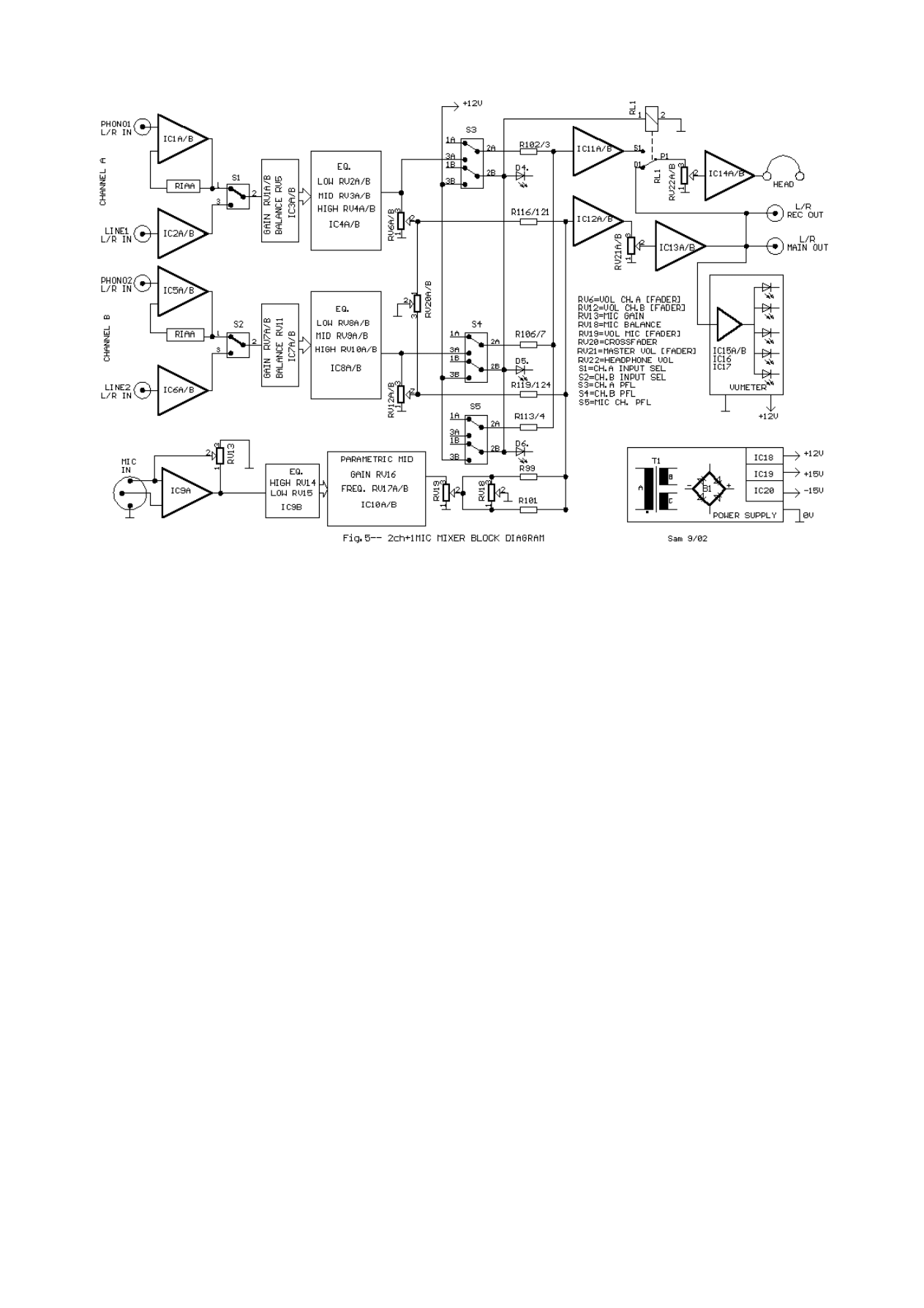
In the Fig.5 appears the block diagram of circuit, which it will help in the comprehension of logic of circuit.
Wyszukiwarka
Podobne podstrony:
Microphone Techniques for Stereo Recording
stereotypy 5
Stereotypy 3
Prezentacja stereopsja 2
11 Stereochemia i podstawowa nomenklatura sacharydów i polisacharydów
91 Nw 05 Amator stereo
Przedwzmacniacz Stereo z Regulacją Tonów, pcb 3xna stronie
powt przed maturą, StereometriaN
Stereometria Łatwa
stereometria, Szkoła-LO, MATEMATYKA
Pomiar widzenia stereoskopowego, POLITECHNIKA POZNAŃSKA, LOGISTYKA, semestr III, ergonomia
stereotyp psych
69 Rola stereotypów i uprzedzeń w komunikowaniu międzynarodowym
MTC CR3000 Car Stereo Head Unit
Farina Reproduction of auditorium spatial impression with binaural and stereophonic sound systems
Penncrest 5905 Stereo Receiver
3 Mechanizm Stereotypizacji
więcej podobnych podstron