
Classification Confidential
Doc Number
Date
May 25, 2007
Version
Draft v0.1
GSM RF Debug Tool Operating
Manual
ASUSTeK Computer Inc.
Mobile Communication Business Unit
R&D Div.1
Writer: YC Chang
Reviser:Aden Chang
1. Purpose & Scope
The purpose of this document is to describe the guidelines and main
building blocks for the ASUS Hermon repair tool. The document describes the
calibration process required for repairing and measuring the phone
functionality. These calibration processes consist of a set of independent
calibration procedures, however we need to initialize the IFL (Intelligence
Framework Libraries) first before we use them.
The document will focus on the GSM system and introduce how to use the
repair tool for repairing and measuring the phone functionality. The outcome of
the calibration process is a set of parameters that shall be loaded two
databases on the PC and on the phone.
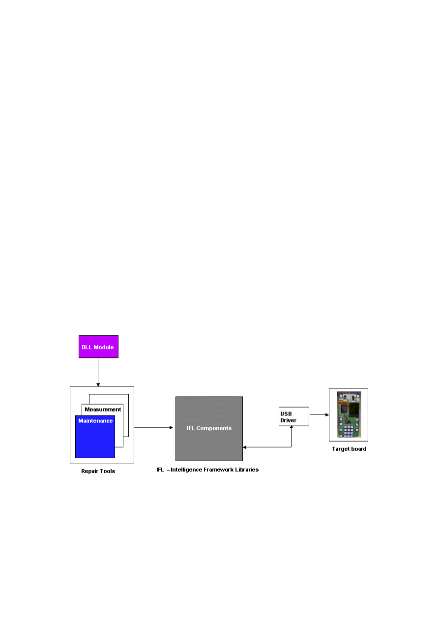
2. Hermon Repair Tool Hierarchy
DLL Module:(build with Visual C++)
Base on HMDSender.dll and reference Intel HTS 2.01 source code
Application Side:(create by C++ Builder)
User interface
Combine the export functions and test procedures
Show result and information
Hermon repair tool features the following capabilities:
Flexibility. (easy to add extended functions or create new method by
update DLL module)
Auto identifies USB connection between application tool and target
board.
Set and control UE in difference mode. (production mode/operational
mode)
GSM system – preliminary finish TX/RX debug functions.
Embedded other useful function in repair tool.
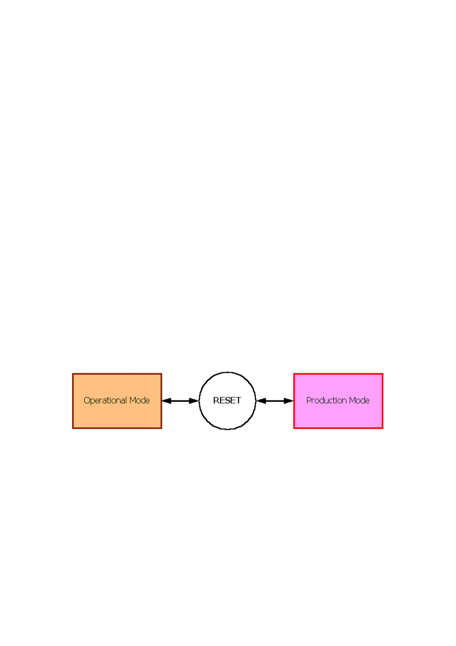
3. General Description
The Hermon software has two main states as shown in below.
There are two main operating modes,
Operational Mode
Default operating mode.
Normal operation of the system.
Production Mode (Calibration Mode)
Production mode is used mainly for calibration activities, thus no
call processing activities are required.
This mode can be entered only after reset (or wake-up).
This mode requires the system to disable the protocol stack that the
external control software (e.g. ICAT or Hermon Repair Tool) will
manage the system; it will communicate with the DIAG module.
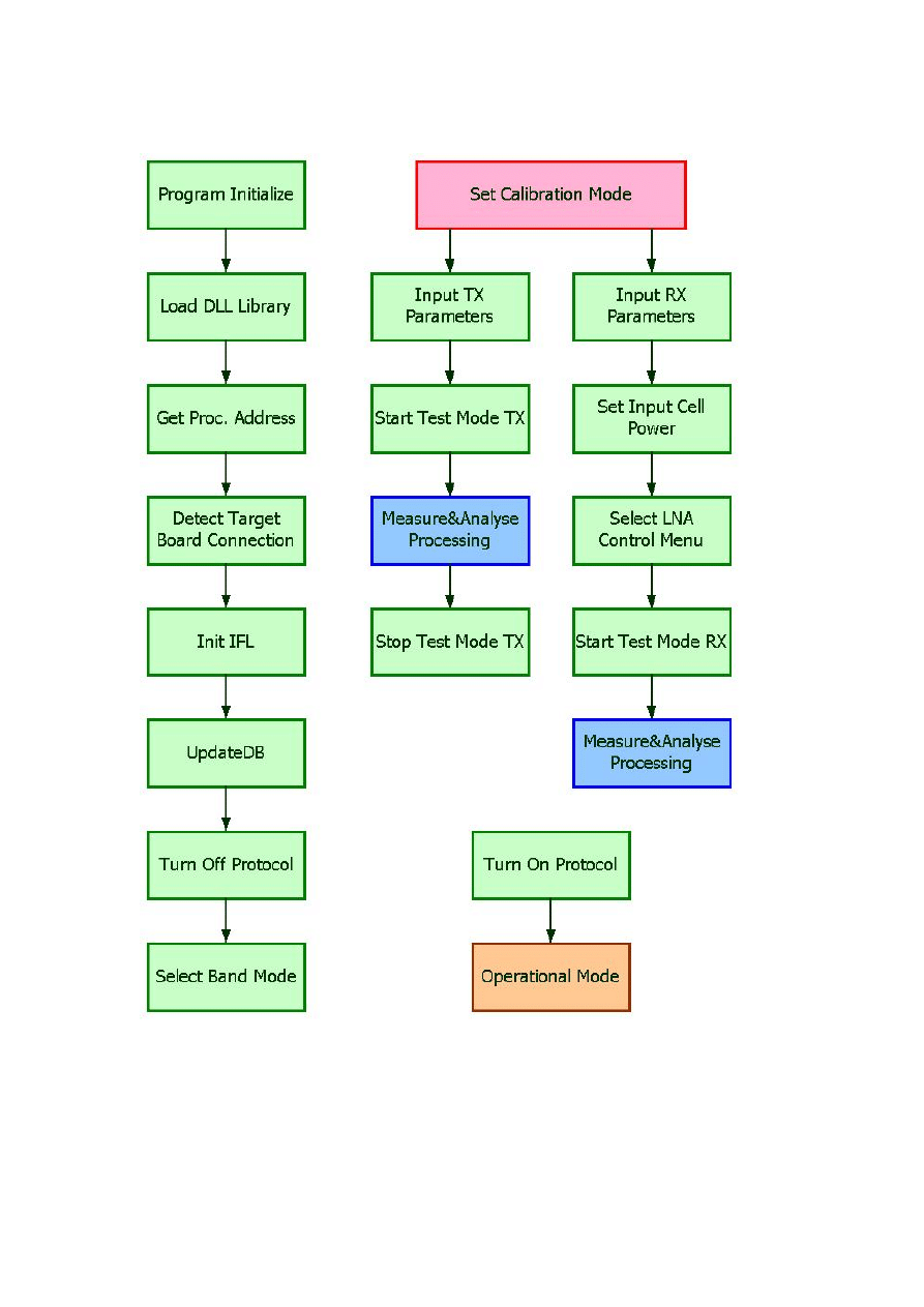
4. System Block Diagram
Following are the main test procedures:
System wakeup
Test equipment initialization
Scenario initialization
Acquisition
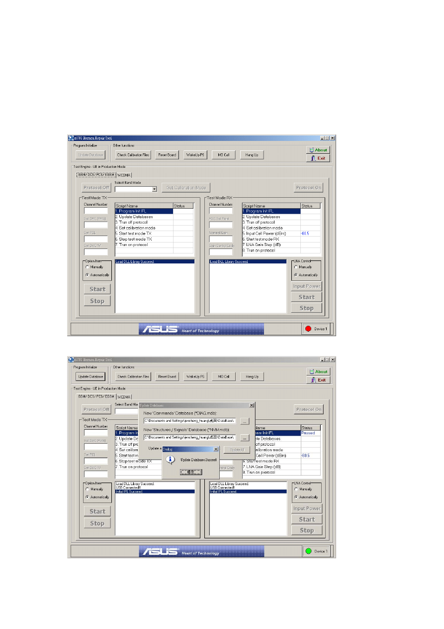
Application Side:
Following figures are the scenario of operating guidelines. You can refer to the
main building blocks in the below too.
1. Start the program and power on the target then wait the device connection.
2. Update database
4. Fill out the data then press following button:turn off protocol
select band
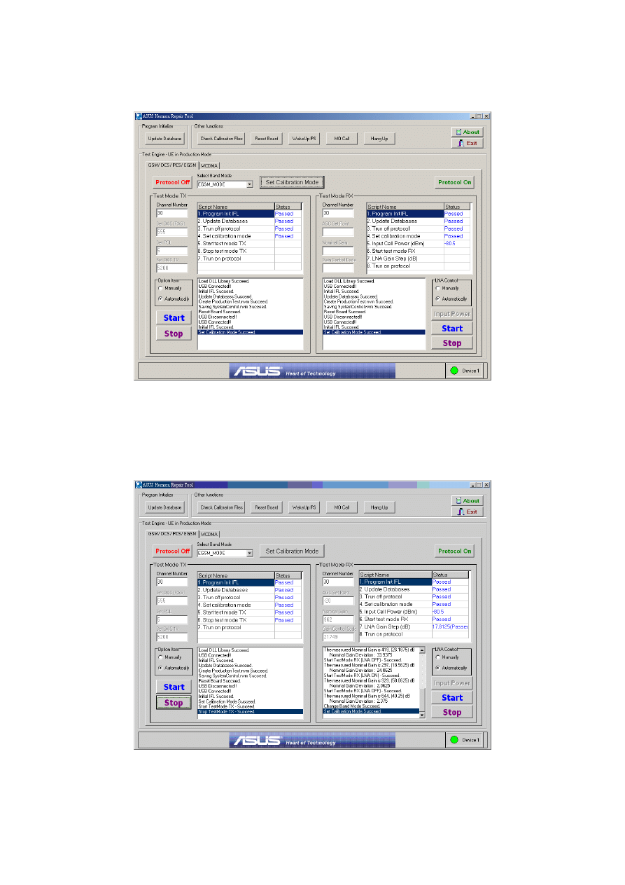
mode
set calibration mode
5. Run the test scenario:
TX – Remember press STOP button when you finished TX.
RX – You can select LNA Control option before press START button.
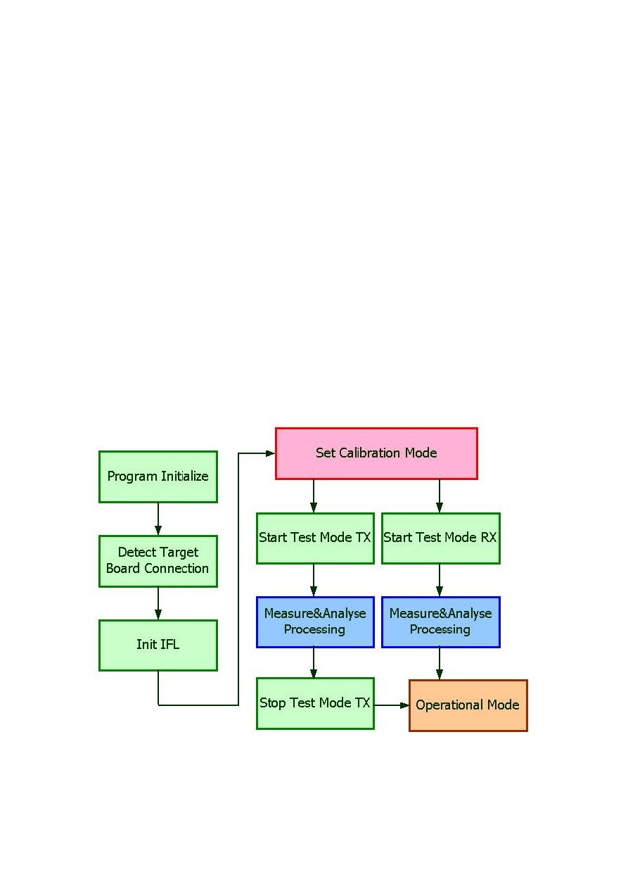
The main building blocks:
Appendix
Other reference
:
ASUS Hermon Repair Tool V1.0
使用說明
.doc
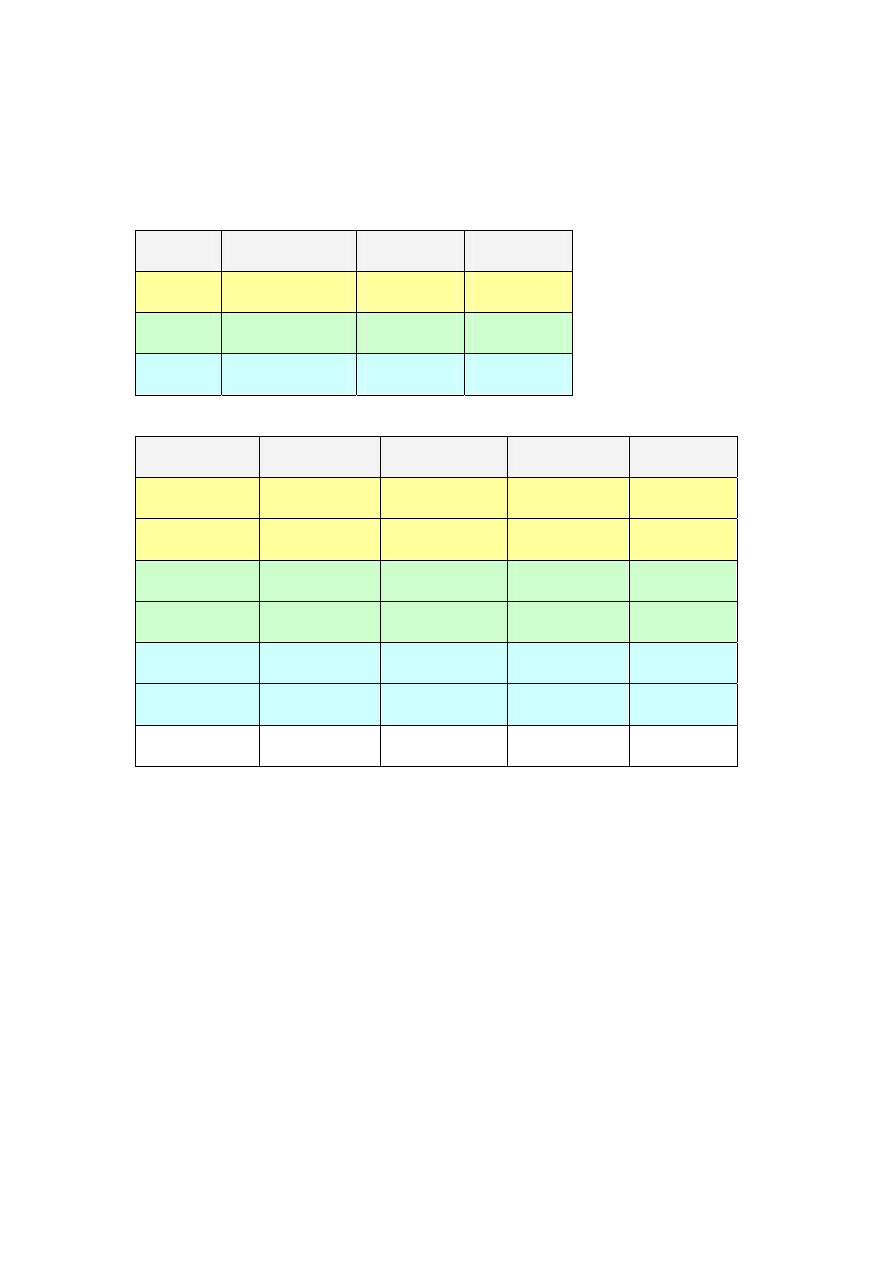
About automatically option parameters value
Test Mode TX
Band
PAG_Value
PCL
DAC1V
DCS
580
0
5200
PCS
550
0
5200
EGSM
555
5
5200
Test Mode RX
Band
PGA_Value
Input Power
GainCode
LNA State
DCS
960
-80dBm
0x73f4
ON
667
0x73f5
OFF
PCS
962
-80.125dBm
0x54f4
ON
682
0x54f5
OFF
EGSM
966
-80.375dBm
0x4f4
ON
697
0x4f5
OFF
Recommend
-80.5dBm
Wyszukiwarka
Podobne podstrony:
Halley Calibration Tool SOP
Halley WCDMADebug Tool SOP
Halley Pre RF Test Tool Beta
2 Planowanie produkcji SOP
93 1343 1362 Tool Failures Causes and Prevention
GSM
SYSTEM OCHRON PRAWNEJ Wykla 17[1].10.2009, Dokumenty STUDIA SKANY TEXT TESTY, ADMINISTRACJA UNIWEREK
GSM to system telefonii komórkowej
SOP opracownie
dpf doctor diagnostic tool for diesel cars function list
launch cresetter oil lamp reset tool introduction
original c68 retail diy auto diagnostic tool manual
16 197 208 Material Behaviour of Powder Metall Tool Steels in Tensile
SOP UE-II 19[1].12.2009, Dokumenty STUDIA SKANY TEXT TESTY, ADMINISTRACJA UNIWEREK WROCŁAW MAGISTER,
SOP 8
Spraw SOP
electric brake service tool ebs301
21 269 287 Effect of Niobium and Vanadium as an Alloying Elements in Tool Steels
więcej podobnych podstron