
400 Commonwealth Drive, Warrendale, PA 15096-0001 U.S.A.
Tel: (724) 776-4841 Fax: (724) 776-5760
SAE TECHNICAL
PAPER SERIES
2000-01-0942
More Torque, Less Emissions and Less Noise
M. F. Russell, G. Greeves and N. Guerrassi
Delphi Diesel Systems
Reprinted From: Advances in Diesel Fuel Injection and Sprays
(SP–1498)
SAE 2000 World Congress
Detroit, Michigan
March 6-9, 2000

The appearance of this ISSN code at the bottom of this page indicates SAE’s consent that copies of the
paper may be made for personal or internal use of specific clients. This consent is given on the condition,
however, that the copier pay a $7.00 per article copy fee through the Copyright Clearance Center, Inc.
Operations Center, 222 Rosewood Drive, Danvers, MA 01923 for copying beyond that permitted by Sec-
tions 107 or 108 of the U.S. Copyright Law. This consent does not extend to other kinds of copying such as
copying for general distribution, for advertising or promotional purposes, for creating new collective works,
or for resale.
SAE routinely stocks printed papers for a period of three years following date of publication. Direct your
orders to SAE Customer Sales and Satisfaction Department.
Quantity reprint rates can be obtained from the Customer Sales and Satisfaction Department.
To request permission to reprint a technical paper or permission to use copyrighted SAE publications in
other works, contact the SAE Publications Group.
No part of this publication may be reproduced in any form, in an electronic retrieval system or otherwise, without the prior written
permission of the publisher.
ISSN 0148-7191
Copyright © 2000 Society of Automotive Engineers, Inc.
Positions and opinions advanced in this paper are those of the author(s) and not necessarily those of SAE. The author is solely
responsible for the content of the paper. A process is available by which discussions will be printed with the paper if it is published in
SAE Transactions. For permission to publish this paper in full or in part, contact the SAE Publications Group.
Persons wishing to submit papers to be considered for presentation or publication through SAE should send the manuscript or a 300
word abstract of a proposed manuscript to: Secretary, Engineering Meetings Board, SAE.
Printed in USA
All SAE papers, standards, and selected
books are abstracted and indexed in the
Global Mobility Database

1
2000-01-0942
More Torque, Less Emissions and Less Noise
M. F. Russell, G. Greeves and N. Guerrassi
Delphi Diesel Systems
Copyright © 2000 Society of Automotive Engineers, Inc.
ABSTRACT
For many years, compression ignition combustion has
been studied by a combination of generic studies on fuel
spray formation and analysis of results from single and
multicylinder engines. The results and insight have been
applied to design and develop advanced fuel injection
equipment for high-speed direct injection engines.
Experimental fuel injection equipments, including early
common rail designs, have been matched to combustion
chambers in single cylinder research engines to tackle
the conflicting requirements of efficiency and minimum
nitric oxide formation, combustion noise and soot. A
clear strategy evolved from the work with experimental
equipment that is being applied to multicylinder engines.
If sufficient oxygen is available in the gas charge trapped
in each cylinder, the LDCR common rail injection system
will provide the fuel required to develop high torque at low
engine speeds. Rate modulation reduces noise,
unburned hydrocarbon and nitrogen oxide emissions to
meet the emissions limits in Europe (Euro III), with low
fuel consumption. This is due in a large part to the rapid
actuation of the control valves and rapid response of the
nozzle in the LDCR injectors.
INTRODUCTION
The prime reason for specifying a compression ignition
powerplant is, and always has been, good fuel economy.
Increasing concern over how carbon dioxide emissions
may affect the global environment provides an additional
reason for using the most efficient powerplant.
The market for diesel powertrains in Europe is
demanding higher torque with better refinement. For the
foreseeable future, the legislation limiting emissions is
being made more stringent. The key components, which
control engine torque, emissions, noise quality and
specific fuel consumption, are the fuel injection
equipment and the air management system
Compression ignition direct injection (c.i.d.i.) combustion
can be operated at high boost pressures, to provide high
torque. The approach favored by most designers is to
use heat energy in the exhaust to drive a turbocharger
and so provide the requisite boost. As turbochargers
develop, more air is being made available to the
combustion processes at low engine speeds, and the
response during engine transients is improving. The fuel
injection equipment has to develop in parallel, to provide
more fuel at low engine speeds and to impart more
energy to the fuel sprays. Higher injection pressures are
required, partly to mix the fuel effectively with an air
charge which is compressed to a higher density by the
high boost to provide a high power output; and partly to
reduce soot generation.
The demand for more refined powertrains for passenger
car applications can be met by pressure charging at high
engine speed conditions. Precise control of the initial
quantity and rate of injected fuel is essential to control
noise originating in the combustion at low engine speeds
and during acceleration after a period of idling, or driving
in heavy traffic
(1,2)
. The modulation required of the initial
rate of injection to control combustion noise changes with
engine operating condition. Modifications to conventional
rotary distributor pumps and injectors were developed
earlier
(3)
to provide a step in the initial rate of injection
(IRC), or a single pilot which reduced combustion noise.
However to attain refinement comparable to spark
ignition engines, more sophisticated injection rate control
is necessary. In addition, more sophisticated control of
fuel delivery is needed to control vibration and shunt
adequately.
Most new road vehicles sold in North America, Europe,
Japan and other developed countries have to comply with
increasingly stringent legislation that limit exhaust
emissions, to improve air quality where road vehicles are
used in large numbers. The automotive industry has
provided increasingly sophisticated technical solutions to
reduce exhaust emissions, as the alternatives are less
acceptable. In general, air quality problems are most
acute in urban areas where the ambient air is stagnant,
which is also where engine and exhaust temperatures
are relatively cool, due to the urban driving conditions.
However, one important class of emissions, oxides of
nitrogen, is emitted mostly when efficient engines are
running at cruise conditions, when they are hot.
Fuel injection equipment manufacturers have to decide
which generic type of product will be appropriate in the
changing marketplace:
2
• Advanced High Pressure Rotary Distributor Pumps
with electronic control of delivery and timing.
• Electronic Unit Injectors and unit pumps with smart
injectors.
• Electrically-actuated common rail and accumulator
systems (which can take many forms).
Fuel injection systems based on each of these generic
types can be designed to provide high injection
pressures at low engine speeds. However, the rate of
heat release from each combustion event has to be
tailored to ameliorate combustion noise and minimize
nitric oxide formation for each engine application.
Additional rate control devices have been developed as
extra features in the conventional pump-pipe-nozzle
systems, but it is much better to incorporate these
requirements into the basic design of any new fuel
injection equipments to minimize costs.
This paper describes briefly some fundamental work
which underpins the design of a Common Rail fuel
injection system for compression ignition engines. This is
divided into Spray Form and Rate of Injection sections.
Some results from a single cylinder research engine
follow, to show the potential of this system. The Common
Rail fuel injection system was described in an earlier
paper
(4)
. This paper focuses on features, which deliver
some solutions to the conflicting requirements of the
European the marketplace, and the legislation intended
to improve and maintain air quality. The paper concludes
with some results from a multicylinder engine.
In this paper, the following abbreviations are used: -
FIE for fuel injection equipment,
RoHR for rate of heat release.
RoI for rate of injection.
Pilot for one or more injections ahead of the main
HSDI for high speed direct injection
VCO for (needle) valve covers (nozzle hole) orifice
CN for cetane number
Tdc for top dead centre
HC for Unburned Hydrocarbons
NOx forOxides of Nitrogen
PM for Particulate Matter
SPRAY FORM
For many years, it has been common knowledge that
visible smoke emissions fall when injection pressure is
raised, provided that the quantity of fuel deposited upon
the wall is not excessive. Greeves developed a Maximum
Useful Rate from data from 10 DI engines.
(5)
Herzog
(6)
showed, with results from a HSDI engine, that if the
nozzle hole size was reduced, further significant
improvements were possible. The gains were ascribed to
better ”atomization” of the spray and faster rates of air
entrainment and mixing in the fuel vapor jet.
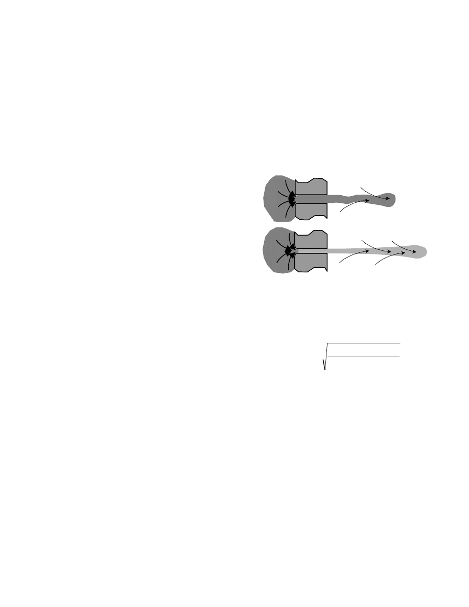
Soteriou and Andrews showed that cavitation occurs in
large scale models of nozzle holes.
(7,8)
Their work
includes not only basic axisymmetric flow into single
holes, (Fig 1) but also flow through complete large scale
models of fuel injection nozzles. They have tested sac-
type nozzles and types in which the needle valve covers
the nozzle orifices (VCO) nozzles. The spray forms
produced by real nozzles are reproduced by the large-
scale models. They have shown that fine cavitation
appears in the fuel within the nozzle hole as the pressure
drop across the nozzle hole is increased. At even higher
pressures, this fine foam-like cavitation fills the whole
cross section and length of the hole. (Fig. 1)
Figure 1.
At high injection pressures, the fuel cavitates
as it passes through small nozzle holes.
The effect occurs when the cavitation number exceeds a
critical value.
Cavitation Number =
Where P
upstream
is injection (seat) pressure
and P
downstream
is cylinder pressure
and P
vapour
is vapor pressure
The effect is seen most clearly with axisymmetric models.
In real nozzles the flow is disturbed just upstream of the
nozzle hole, such as by passing over an edge and into
the hole, which is set at an angle to the flow past the
needle tip.
(9)
Both increase the energy levels in the
directions normal to the main flow direction. To ensure
that the flow conditions are similar in all the nozzle holes,
the holes must be symmetrically disposed about the
nozzle axis, which infers a nozzle axis aligned with the
axis of the combustion bowl. This in turn requires a slim
injector design to fit into the space available.
The consequences of running the nozzle hole in a fully
cavitated condition are:-
1. to fragment the fuel very finely,
2. to provide a good basis for further fuel atomization
and evaporation in the air charge.
High pressure spray
through small holes
Low pressure spray
More air entrainment
vapour
downstream
downstream
upstream
P
P
P
P
−
−
3
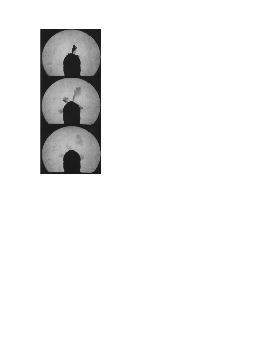
The evaporation of the fuel as the surrounding air is
entrained into each spray, as illustrated in Figure 2.
Figure 2.
Shadowgraphs of the spray from a 5-hole
Common Rail injector with the rail pressure
set to 500 bars. The 2 cu mm pilot has
dispersed in 0.3 ms
Figure 2 shows a shadowgraph of the liquid phase of a
spray injected at 50 MPa into nitrogen at 4.5 MPa in this
facility. The liquid fuel is fragmented and expands
steadily as it reaches into the chamber, thus entraining
hot gases. In a companion paper to this one
Kunkulagunta describes the technique and presents
more results.
(10)
Several aspects of the spray form affect the soot
generated; including the spray tip penetration, included
angle, targeting, and uniformity across a section. Most of
these can be measured with the combination of
shadowgraphy and Schlieren available in house.
Greeves and Partridge
(11,12)
have developed a spray
mixing model and thoroughly validated the predictions
with data from the shadowgraphs and single cylinder
engine results. This model is used to predict the liquid
phase penetration, the vapor phase penetration and the
equivalence ratio at any point in the spray to assist
interpretation of anomalous engine results. This model
has been applied to DI and HSDI engines fitted with
many types of research FIE in the past.
In an alternative approach, the factors which affect soot
emissions were found by applying a set of six different,
developed, FIE specifications to a single HSDI engine.
Measurements were made of smoke, cylinder pressure,
needle lift and line pressure, from which seat pressure
and Rate of Injection were calculated. The effects of the
several parameters involved were found by incorporating
prior knowledge of soot generation in HSDI combustion
as factors in a multiple regression analysis. For the first
generation HSDI chosen, the primary factors were the
volumetric efficiency, minimum RoI after ignition, rate of
collapse of line pressure and seat pressure. The most
interesting factor in this correlation was the minimum rate
of injection after ignition across the load and speed range
of this HSDI engine. This work reinforced the findings
from numerous studies with research FIE and provided a
clear indication of the requirements for a successful
Common Rail FIE to the designers.
(13)
INJECTION RATE MODULATION
Injection rate modulation, be it by injecting one, or more
pilot injections ahead of the main, or by controlling the
initial rate of injection (IRC), affects both the fuel-air
mixing and the rate of heat release. The modulation of
initial rate of mixing affected the soot generation and HC
emissions primarily. The modulation of the rate of heat
release reduced combustion noise and the formation of
nitrogen oxides. If initial rate modulation is implemented
by restricting the needle lift, the restriction upstream of
the nozzle hole reduces the pressure drop across the
hole and hence the spray momentum and consequently
the rate of fuel-air mixing at the start and end of injection.
The work on injection rate modulation was initiated to
reduce noise generated by compression ignition
combustion processes. A special Combustion Noise
Meter was produced by Young and Russell to expedite
these studies
(2,14)
. This embodied the Mean Free Field
Response for a number of automotive engine structures,
and provided a single number index of the noise-
generating propensity of any cylinder pressure
development in dB(A) re 20
µ.
Pa. The Combustion Noise
figures in this paper are measured with this meter, and
are directly comparable with other published results.
To reduce nitric oxide formation, the aim of injection rate
modulation is to reduce the initial Rate of Heat Release,
and hence the peak combustion temperature. In general,
this reduces to minimizing the peak cylinder pressure;
hence good correlations are found between nitric oxide
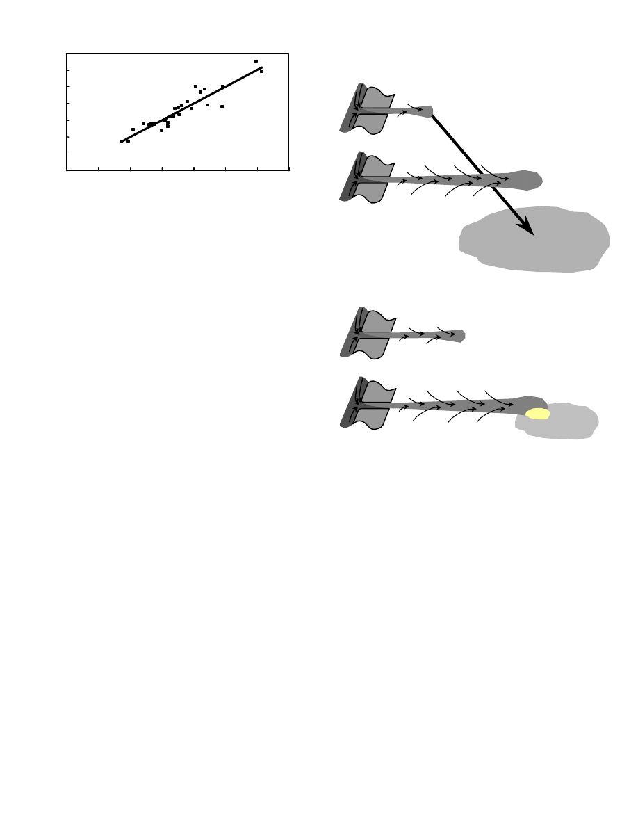
emissions and peak cylinder pressure. (Fig 3) However,
as the graph in Figure 3 shows, the load has a significant
effect. The combustion chamber wall temperatures rise
affect the charge air temperature, which rises when the
engine is run under high loads.
4
Figure 3.
Regression between nitric oxide emissions
and a combination of peak cylinder pressure
and load.
Of the six common sources of unburned hydrocarbon
emissions,
(15)
Greeves’ “lean limit source”
(16)
can be
controlled by modulation of the initial rate of injection.
Fuel which is injected early in the cycle has time to travel
across the combustion chamber and diffuse into a
mixture which is too lean to burn. An appropriately timed
pilot injection, or appropriate control of the initial rate of
injection, can reduce HC from this source by 50%.
The following diagrams illustrate the generic results
deduced from systematic engine experiments in the
1980’s and supported by shadowgraph observations of
spray development more recently. In each case, a small
pilot is injected ahead of the main injection.
The first case, illustrated in Figure 4a shows the diffusion
of a very early pilot, for example 30 to 60
°
c.a. btdc, or
more. The early pilot dispersed and mixed with the air
charge to form a very lean mixture before the charge
compression raised the temperature sufficiently to cause
autoignition. Such mixtures became too lean to
autoignite, or sustain a flame front, so they did not burn
completely, so the emissions of unburned hydrocarbons
would increase.
(16)
Alternatively, as illustrated in Figure 4b, when a single
pilot was timed to ignite the main injection, the noise
originating in the combustion process was reduced; by up
to 11 dB(A) as measured by the Combustion Noise
Meter. The pilot quantity and timing minimized the fuel
injected and mixed during the ignition delay period. This
minimized the initial RoHR and initial rate of cylinder
pressure rise. However, the proportion of the fuel
delivery which had to be burned during the diffusion burn
phase of combustion was maximized, which increased
soot generation and particulate mass emission. A further
increase in injection pressure was usually sufficient to
improve the mixing process during the diffusion burn and
thus restore the particulate mass to its former value. This
pilot timing was most useful to reduce HSDI acceleration
noise
(17)
. By minimizing the fuel injected during the
ignition delay, HC emissions from the lean limit source
can be minimized. The pilot timing required was typically
3 to 10 crank degrees before the main injection at speeds
up to 3000 revs/min. At higher speeds, there is less
potential for noise reduction by pilot and IRC.
Figure 4a. Early pilot injections formed lean mixtures.
Figure 4b. Pilot injections timed to ignite the main
injection (ignition delay-1
°
crank angle
typically) reduced noise and the lean limit HC
source.
If a pilot was injected a few crank degrees earlier, or later,
than the optimum for combustion noise control, the
ignition delay of the main injection was reduced. As the
shadowgraphs in Figure 2 show, the pilot fuel dispersed
in less than 0.3 milliseconds. The momentum of the pilot
fuel mass is imparted to the air charge. When the main
injection starts, the first elements of the main mix with the
pilot, so reducing the ignition delay of the main injection
and hence combustion noise and HC. The increase in
soot generation is smaller, since more fuel has been
injected during the ignition delay period, than the
optimum for noise control.
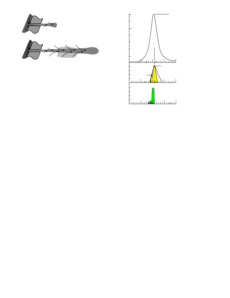
If the pilot is injected very close to the main injection,
(Figure 4c) the effect is similar to initial rate control, which
some call a “boot-shaped” injection diagram. When
injected very close to the main, the pilot has little time to
mix before the main injection, so the noise reduction is
less that that at optimum timing for noise but less soot is
formed in the diffusion burn.
0
200
400
600
800
1000
1200
1400
0
200
400
600
800
1000
1200
1400
Nitric Oxide concentration in ppm
12.5 Peak Cylinder Pressure (in bars) + 1.7 Load(%) - 479
Early pilot injection
Pilot diffuses into
a lean mixture
Pilot injection
Pilot injection auto-ignites
as main is injected
5
Figure 4c. Pilot injected very close to the main injection.
The most extreme method of modulating the initial
injection rate is to inject part of the fuel into the manifold,
which is also known as fumigation.
(18)
This is a well-
known means to reduce noise, but it has limited use in
shaping the rate of heat release diagram. Some early in-
house work made use of the ultrasonic atomizer
developed by Bradbury
(19)
to produce finely divided
droplets of diesel fuel in the intake manifold. Work on
fumigation was reported earlier.
(20)
With up to 15% of
the full delivery fuel fumigated, useful reductions in noise
and smoke were observed for the same mean effective
pressure. If more fuel was fumigated, it auto-ignited well
before top dead centre.
The several investigations into the effects of rate
modulation upon compression ignition combustion were
summarized in earlier papers.
(11)
by a diagram, which is
reproduced here for convenience as Figure 5. This
summary was developed around a Rate of Heat Release
diagram for low combustion noise. Two alternative
approaches to providing the optimum RoHR were
identified. One involved a combination of pilot injection
and Initial Rate Control, which has been incorporated into
the EUI FIE for HSDI engines. The second envisaged
multiple pilot injection with close pilot-to-pilot and pilot-to-
main spacing; this has formed the basis for the LDCR
Common Rail FIE for HSDI engines. The RoHR from two
pilots and a main is indicated in Figure 5 to compare with
the optimum RoHR for Combustion Noise.
The Light Duty Common Rail design was based upon
specific in-house research. It was designed to provide
some solutions to foreseeable problems which engine
designers and developers would meet as they evolved
engines to provide a high specific torque, with low noise
while complying with ever more stringent exhaust
emissions requirements.
Figure 5.
Summary of typical HSDI engine
requirements for rate shaping.
THE COMMON RAIL FIE SYSTEM
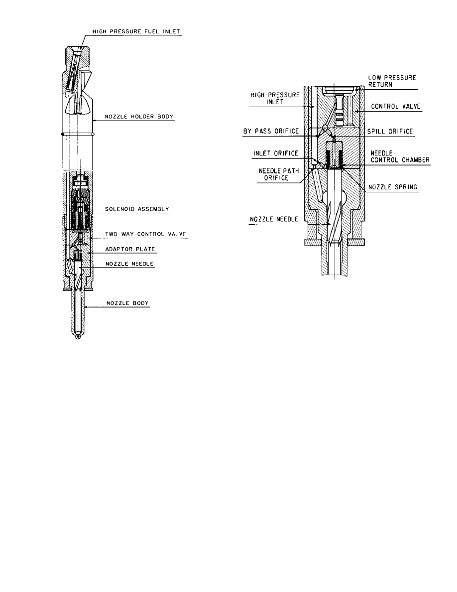
INJECTOR – The key to obtaining the requisite
performance is rapid actuation. The injector is designed
as an hydraulic servomechanism, in which the control
valve is very light in weight and the slave piston is moved
rapidly by fuel at high pressure. The control valve has a
positive seal at a conical seat to minimize leakage and is
either open or shut (two-way valve). The slave piston is
the needle of the injector and fuel pressure is applied to
the top face of the needle as well as the bottom. A
section of the LDCR injector is shown in Figure 6. A
scrap section of the servomechanism is shown in
Figure 7.
When the needle of the injector is closed, the pressure at
the top is applied over the whole needle cross section
area; and the same fuel pressure is applied to the bottom
of the needle outside the seat diameter. The net force
developed by fuel pressure assists the light spring to
keep the needle closed. The control valve operates in a
chamber connected to the fuel space at the top of the
needle and connected via a small hole to the line (rail)
pressure. When the solenoid above the control valve is
energized, the control valve is lifted off its seat and the
fuel in the valve chamber is drained to the backleak. The
pressure above the needle falls as fuel flows through the
spill orifice, until the net force is sufficient to open the
needle. When the needle starts to rise, fuel is drawn
from the line and the local line pressure near the needle
tip drops, however this pressure is applied to the whole
cross section of the needle.
Late pilot injection hardly mixes
before it is overtaken by the main
Late pilot injection
4
40
0
60
0
20
0
40
Cylinder
Pressure
in bars
RoHR in
kJ/kg
o
RoI in
cu mm/
o
Peak cylinder pressure
indicates high peak cycle temperature
which indicates rapid formation of
Nitric Oxide
A high peak rate of heat release causes
a high level of combustion noise, so
pilot injections and/or IRC are introduced
to control the initial rate of combustion
0.5 cu mm of pilot followed by initial rate (IRC)
High pressure through small holes reduces soot
Abrupt termination reduces soot
RoHR of
2 pilot inj.
6
Figure 6.
LDCR Common Rail injector
When the needle is open and it is to be closed, the
control valve is closed and pressure on the top of the
needle builds up to that in the fuel line. A needle-path
orifice is included in the drilling to the nozzle to provide
sufficient pressure drop to force the needle to close
rapidly. A small spring assists the needle to close.
The balance between the orifices determines the needle
velocity on opening and closing. The orifices can be
tuned during application to limit the initial rate of injection
and optimize the rate of termination. All these drillings
are in one component, the adaptor plate.
The LDCR injector was designed to provide multiple
injections such as pilot(s) close to the main injection to
reduce Combustion Noise to an acceptable level and a
post injection to reduce soot formation. As soon as the
needle opens, fuel is injected and an hydraulic expansion
wave travels up the drillings in the injector and along the
high pressure line to the rail. This hydraulic wave is
reflected back towards the injector. The lines are made
long enough to ensure that the returning wave does not
degrade the end of injection. The system tuning is
important to ensure that multiple injections are possible
with minimal interference between injections. Each
system is precisely simulated to optimize its
performance.
Figure 7.
Enlarged section of the compact
servomechanism, which provides the rapid
response, required for close pilot(s) and main
injections.
Figures 6 and 7 illustrate also the extended guide
nozzles, which have been developed for the LDCR. The
inlet drilling in the nozzle body is taken to a gallery high in
the body. The metal between the drilling and the guide,
which is subjected to high stress as the pressure in the
injector is raised to 160 MPa (1600 bars) is more
substantial than previous designs.
The flutes below the gallery conduct the fuel around the
needle valve stem to the annular passage above the
needle seat. The fluted section greatly increases the
guide length and controls the lateral movement of the
needle tip across the seat.
The actuator is a small electromagnet, that attracts an
armature, which is integral with the 2 mm dia. balanced
valve. This valve forms the control valve for the
servomechanism.
THE COMMON RAIL – The rail is mounted along the
cylinder head to provide a reservoir of high pressure fuel.
It has an important function in controlling hydraulic wave
action. The rail is a forging which is finish machined and
fitted with special high pressure unions for the high
pressure lines to each injector, the feed line from the
pump and the Rail Pressure Sensor and Pressure
7
Control Valve. The shape of the rail is not important, but
the volume is kept as small as possible to minimize the
energy loss when the engine speed is reduced suddenly
and fuel has to be drained to reduce the pressure to the
value appropriate to low speed operating conditions.
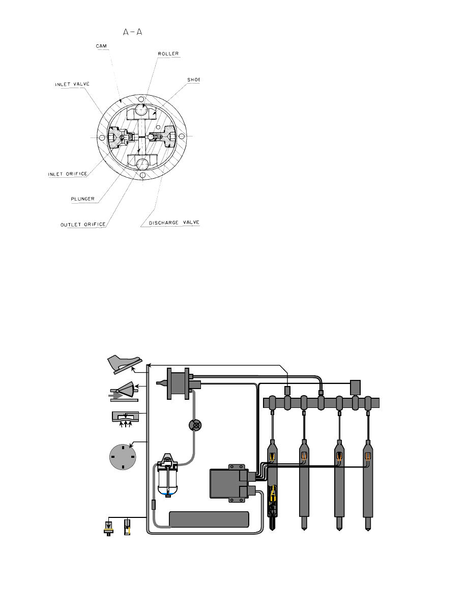
THE HIGH PRESSURE PUMP – The pump is capable of
delivering up to 0.7 cu cm/rev at 160 MPa (1600 bars)
pressure. The pumping principle is that of the internally-
lobed ring cam and opposed plungers developed for the
Company’s Rotary Distributor Pumps. However, in this
pump the cam is rotated by the pump shaft, and the twin
plungers are in a lateral bore in the stationary pump head
as shown in Figure 8. The distributor rotor and sleeve
with small running clearances are unnecessary. The
cam is provided with four internal lobes, so a pair of
plungers, working in a single pumping chamber, pumps
four times per cam revolution.
An internal low pressure pump can be incorporated to
draw fuel from the vehicle tank and fill the space between
the plungers before each pumping stroke. This is a
conventional “Transfer Pump” with four rotating vanes
running in an eccentric housing. Each pumping chamber
is connected to the fuel supply via inlet check valves.
These are spring-loaded plate valves to minimize fuel
displacement and pressure loss.
The pump is fitted with an inlet-metering valve which is
the primary control for rail pressure. The fuel required is
calculated by the Electronic Control Unit (ECU) and only
this much fuel is allowed into the pump, so virtually no
fuel has to be spilled from the rail. At the high pressures,
spilled fuel can be a significant energy loss.
The pump is normally flange-mounted to a front plate, or
timing case of the engine. As an alternative, a mounting
point for a rear bracket and side-mounting bosses are
available, however the structure to which the pump is
attached must withstand the pump torque reaction
without radiating excessive noise, particularly when the
engine is operating at part load.
One of the features of a Common Rail injection system is
that the pump duty cycle is less impulsive than high
pressure inline and rotary pumps. At full fuelling, the
Common Rail pump produces a much smaller pressure
ripple and hence smaller torque reaction ripple at audible
frequencies. This greatly simplifies the mounting design.
However, when inlet metering is used to conserve energy,
the pump will develop pressure only over part of each
pumping stroke; and the torque reaction will fluctuate
accordingly.
Pumps are available either with a single lateral pumping
chamber or with two chambers set at an included angle
of 45
°
, giving eight pumping strokes per cam revolution.
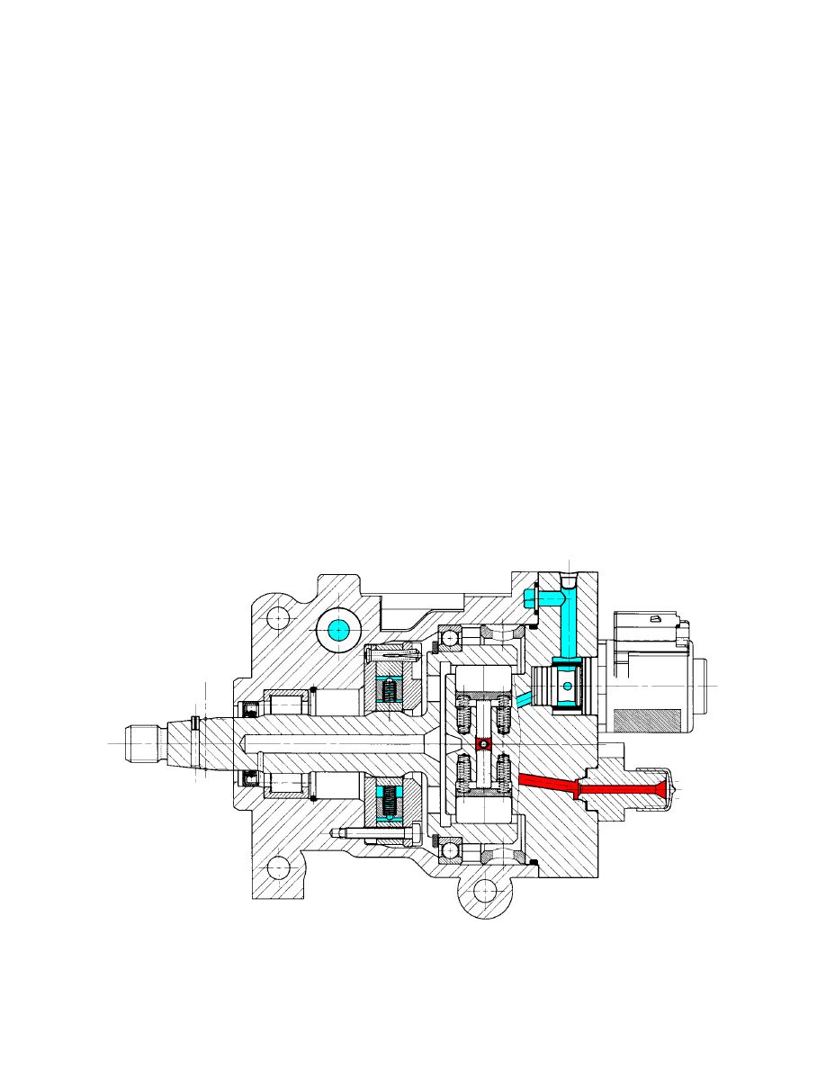
A cross section of the high pressure pump is shown in
Figure 9
Figure 8. Longitudinal section of the high pressure pump for the LDCR Common Rail high pressure pump
8
Figure 9.
Cross section of LDCR high pressure pump,
showing the pumping plungers in one of the
pumping chambers and the associated inlet
and outlet valves.
CONTROL
–
Common Rail FIE requires more
sophisticated control functions than conventional FIE, as
the individual pilot and main injections have to be
programmed for delivery and timing over the whole load
and speed range.
The speed and injection timing signals come from the
engine flywheel. This opens an opportunity to provide
more refinement in the engine torque output by balancing
the torque from each of the cylinders, which has been
described earlier.
(4)
However engine tests have shown
that balancing the engine torque does not necessarily
balance the noise from each cylinder. Accordingly, an
additional facility is provided to sense the onset of
combustion and hence to balance the pilot injections into
each cylinder to further improve refinement.
Another refinement problem which has been noticeable
in some earlier diesel-powered cars has been a fore-
and–aft oscillatory motion, variously termed “shunt”,
“cab-nod”, “judder”, “surge” and “chuggle”. The problem
arises as the torsional resonances in the driveline are
excited by sudden demands for torque, imperfections in
the road, etc. Once excited, the torsional vibration can
be exacerbated by changes in engine torque output with
speed, so forming a self-perpetuating oscillation. This
problem and its solution are described in detail in a
companion paper by Balfour.
(21)
A generic model has been produced of this phenomenon.
Special software is included, which is based on this
model, in the Electronic Control Unit. The model can be
tuned for each vehicle application to damp this
oscillation. This can be combined with the other
refinement solutions to tackle most, if not all, engine-
related NVH problems. Figure 10 shows the hardware
and control system for the Common Rail FIE, with the
sensors required to provide solutions to the refinement
problems described in this section.
Figure 10. Components and sensors of the LDCR FIE.
Rail pressure
Demand
Air mass flow
Manifold
pressure
Rail pressure
control valve
Injectors containing control valves
Crankangle
& sync.
Engine & Fuel
Temperatures
Start of Combustion
Inlet metering
valve
Electronic
Control
Unit (ECU)
High
pressure
pump
Transfer
pump
Fuel tank
Filter
Rail
9
EXHAUST EMISSIONS
NITROGEN OXIDES – When the effects of peak cycle
temperature are considered, a fundamental conflict
emerges for a lean-burn engine in terms of thermal
efficiency-v-NO formation. The thermal efficiency and
hence the specific fuel consumption and the carbon
dioxide emissions are better with a high peak cylinder
temperature. For a particular combustion chamber and
fuel spray geometry, the correlation between NO and
peak cylinder pressure indicates how emissions increase
with peak cylinder temperature. This underlies a
fundamental trade-off between fuel consumption and
oxides of nitrogen emitted from the exhaust, (CO
2
– v –
NO
x
). The trade-off is particularly obvious when the
injection timing is retarded to reduce nitrogen oxide
emissions. Figure 11 shows this trade-off for a recent
HSDI and the current HSDI with Common Rail FIE; at the
2800 revs. / min emissions mode, which is close to cruise
speed.
The peak cylinder temperature depends upon the Rate of
Heat Release and its phasing in the engine cycle. Fuel
which is burned before tdc will elevate this temperature,
but a significant proportion of the heat may be lost before
the crank turns sufficiently to develop useful torque. If
fuel is injected and mixed at such a rate that most of the
fuel burns very rapidly after tdc, then a high peak cylinder
pressure and temperature may be avoided, and the heat
loss and consequent loss in efficiency minimized. In
current combustion processes, the peak cycle pressure
and temperature are kept as low as practicable by
injection rate modulation, using the flexibility of the
common rail FIE, and EGR, to reduce NOx formation.
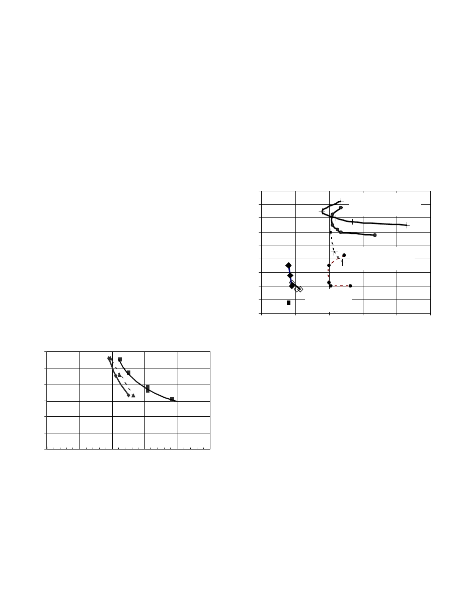
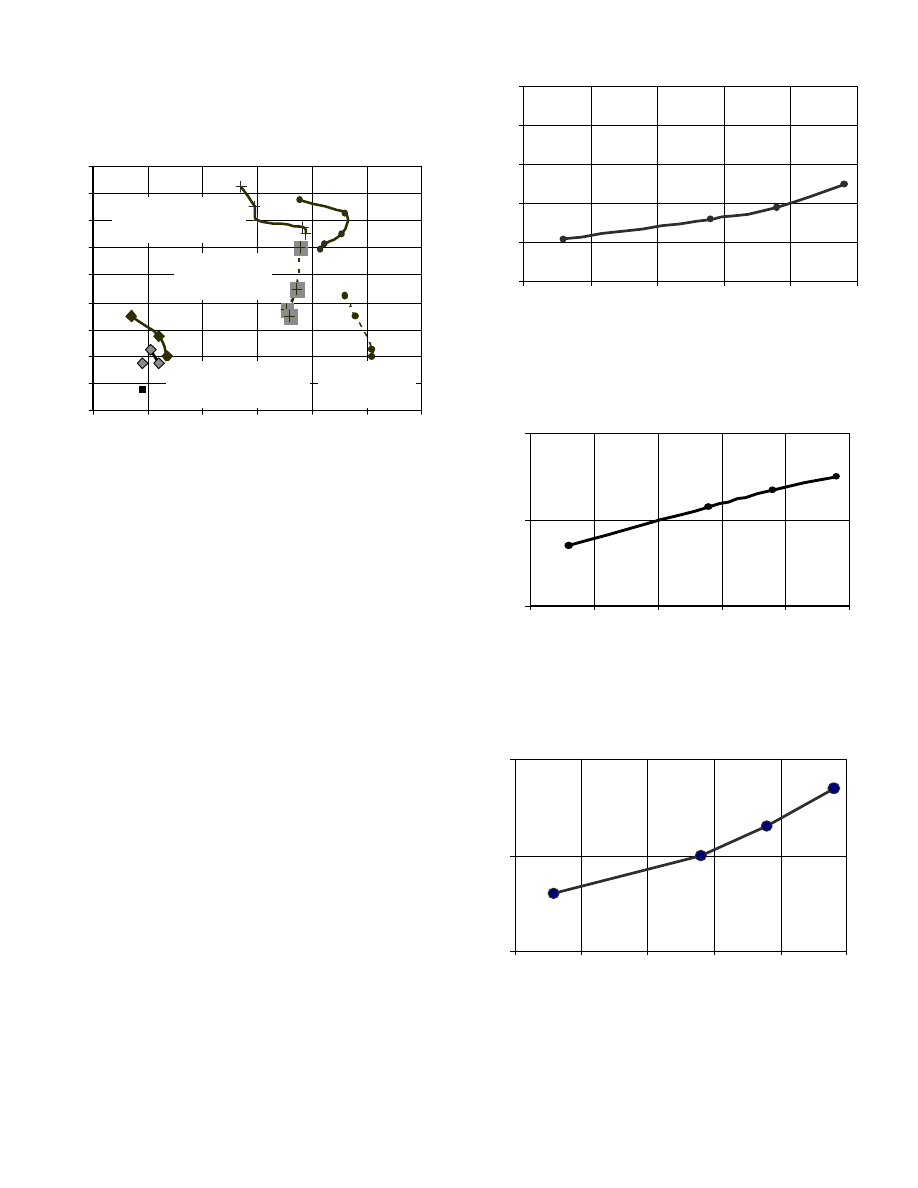
Figure 11. Trade-off between Nitric Oxide emissions and
fuel economy showing the improvement in
economy by fitting Common Rail FIE ( No
EGR).
COMBUSTION NOISE – Combustion noise results can
be plotted against fuel economy and soot emissions
(smoke or particulate matter) to form another critical
trade-off. Figure 12 shows Combustion Noise plotted
against BSFC for three engines typical of a (first
generation) HSDI and an HSDI fitted with common rail
FIE.
In Figure 12, The 1989 HSDIs were the first generation
engines of this type and they were naturally aspirated.
Engines built to designs that are more recent are
turbocharged and quieter when fitted with LDCR
common rail with pilot injection. By adding pilot injection,
both the noise and the economy are improved; however,
the soot increases unless injection pressure is raised to
improve the fuel-air mixing during the diffusion burn to
compensate for the this. The improvements in both the
noise contribution from combustion and fuel economy
can be seen in Figure 12.
Figure 12. Trade-off between Combustion Noise and fuel
economy, at 2000 revs/min Full Load; noise
and fuel economy are better with the common
rail FIE.
A minor contribution to the noise–exciting propensity of
the cylinder pressure development comes from the
compression ratio. The high compression ratios, of 19:1
and more in current HSDI engines, have slightly more
energy in their high frequency harmonics than the earlier
17:1 designs. However, if the cylinder pressure
development is broader because the heat release is
phased later in the cycle, then the noise will be reduced.
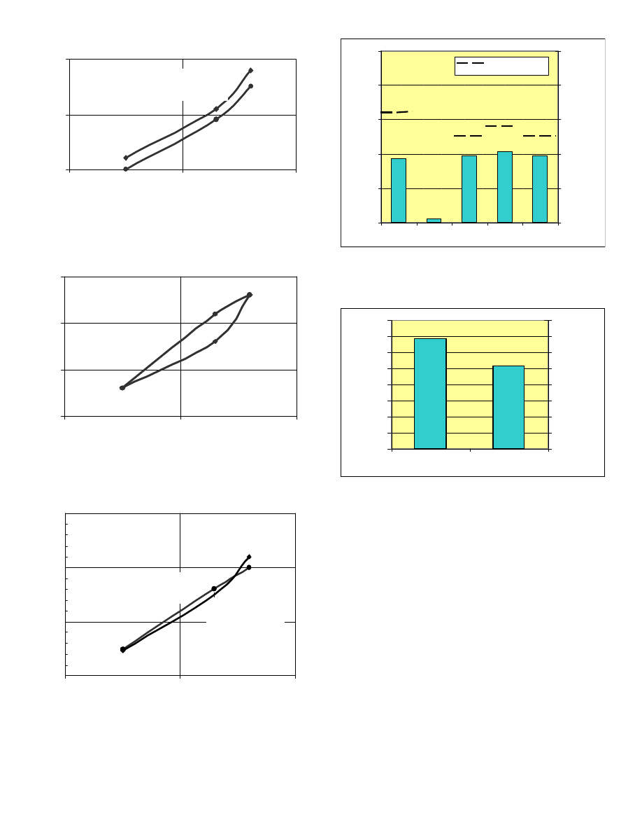
SOOT AND PARTICULATES – In almost all HSDI
engines with traditional FIE, the soot increased when
pilot was added and so phased that the combustion noise
was substantially reduced. The typical increase in soot
can be seen by comparing data joined by the two dashed
lines with those joined by solid lines in Figure 13. In
more recent engine combustion systems, swirl has been
reduced as the number of holes in each nozzle has been
increased. The fuel-air mixing relies more heavily upon
injection pressure in these systems therefore. Hence,
Nitric Oxide emissions in ppm
0
100
200
300
400
500
600
200
220
240
260
280
300
Brake Specific Fuel Consumption in g / kW-hr
80
82
84
86
88
90
92
94
96
98
200
22 0
24 0
26 0
28 0
300
Combustion Noise in dB(A) re 20 micropascals
using the Mean Free Field Response
2 HSDI engines
1989 main inj. only
2 HSDI engines
1989 with pilot
HSDI 1999
with LDCR
Brake Specific Fuel Consumption in g / kW-hr
10
the fuel-air mixing can be improved still further to
compensate for any extra fuel displaced from the
diffusion burn to give improved noise and BSFC.
Figure 13. Trade-off between Combustion Noise and
Smoke at 2000 revs/min Full Load, showing
the reduction in soot generation with LDCR
common rail
The results from the single cylinder research engines
demonstrate that the LDCR common rail FIE can be
combined with suitable combustion chambers and
pressure charging equipment to meet the stringent limits
on road vehicle emissions.
MULTICYLINDER ENGINE RESULTS
The LDCR common rail FIE has been applied to a four
cylinder HSDI recently which complied with Euro III
emissions limits by a 20% margin without aftertreatment
apart from an oxidation catalyst. Smoke, specific fuel
consumption and exhaust emissions are all held to low
values up to maximum torque. Figures 14 to 16 show
how these parameters change with specific torque at the
peak torque engine operating condition.
At rated speed and load, the engine produced 53 kW/liter
specific power while the smoke and maximum exhaust
temperatures met the marque targets, for a passenger
car application. The results at rated speed are shown in
Figures 17 to 19 for an engine fitted with a version of
LDCR with improved hydraulics.
In another application of LDCR to a slightly smaller
engine, the Euro III emissions limits have been bettered
by 25%, as shown in Figure 20a while providing the
required torque and power. The fuel consumption and
carbon dioxide emissions are shown in Figure 20b.
Noise is controlled by suitably-phased pilot injection at
low speed, light load conditions.
Figure 14. Specific fuel consumption at peak torque
conditions.
Figure 15. Exhaust temperatures at peak torque
conditions
Figure 16. Smoke levels at peak torque conditions
Combustion Noise in dB(A) re 20 micropascals
using the Mean Free Field Response
80
82
84
86
88
90
92
94
96
98
0
1
2
3
4
5
6
Smoke in FSU
1989 HSDIs
main only (NA)
1989 HSDI
with pilot
1999 TCI HSDIs
pilot injection
1989 HSDI
with pilot
Specific Torque in N-m / liter
Specific Fuel Consumption in g / kW-hr
205
210
215
220
225
230
150
155
160
165
170
175
Exhaust Temperature in deg C
Specific Torque in N-m / liter
500
600
7 00
150
1 55
1 60
1 65
17 0
1 75
Specific Torque in N-m / liter
Smoke in FSU
0
1
2
150
155
160
165
170
175
11
Figure 17. Specific fuel consumption at and near rated
power
Figure 18. Smoke at and near rated power condition
Figure 19. Exhaust Manifold Temperature at and near
Rated Power
Figure 20a. Emissions from a 1300 kg vehicle fitted with
an HSDI engine and LDCR Common Rail
FIE.
Figure 20b. Fuel consumption of a 1300 kg vehicle fitted
with an HSDI engine and LDCR Common
Rail FIE.
SUMMARY AND CONCLUSIONS
The results from a series of combustion, noise and
emissions studies with experimental fuel injection
equipment have been used as a basis for the design of a
common rail fuel injection equipment which features very
fast response to allow pilot injections and a post injection
close to the main injection.
Single cylinder engine studies show how this FIE can
confer excellent performance and refinement upon HSDI
engine combustion systems while maintaining low
exhaust emissions and good fuel economy.
In multicylinder engines, which complied with Euro III
emissions limits with an adequate engineering margin,
the LDCR FIE increased the specific output up to 53 kW
per liter and maintained refinement due to its flexibility.
Brake Specific Fuel Consumption in g / kW-hr
Specific Power Output in kW / litre
230
235
240
45
50
55
1.20 bars
boost pressure
1.1 bars boost
pressure
1
1 . 5
2
2 . 5
4 5
50
5 5
Smoke in FSU
Specific Power Output in kW / litre
Specific Power Output in kW / litre
600
650
700
750
45
50
55
Exhaust Temperature in deg.C
1.2 bars boost
pressure
1.1bars boost
pressure
0
0,2
0,4
0,6
0,8
1
Gas emissions (g/km)
0
0,02
0,04
0,06
0,08
0,1
Particulate emissions (g/km)
CO
NOx HC+NOx PM
EURO 3 limit
HC
0
20
40
60
80
100
120
140
160
CO2 (g/km)
0
1
2
3
4
5
6
7
8
Consumption (l/100km)
C o n su m p tio n
C O 2

12
ACKNOWLEDGMENTS
The authors acknowledge the permission of the Directors
of the Lucas Diesel Systems to publish this paper.
The authors are part of a team which has been
specifying, designing, developing and applying fuel
injection equipment for high speed direct injection diesel
engines over two decades. They are pleased to have the
opportunity to acknowledge the many contributions to the
work reported here from their colleagues at all the Diesel
Systems sites.
REFERENCES
1. Head, H E and Wake, J D “Noise of diesel engines
under transient conditions” SAE paper No. 800404
Soc. Auto. Engrs. Congress Detroit Feb 1980.
2. Russell M F and Haworth R “Combustion noise from
high speed direct injection diesel engines” Soc. Auto.
Engrs. SAE paper 850973 in P-161 Proc. Surface
Vehicle Noise and Vibration Conference in Traverse
City May 1985.
3. Russell, M F and Lee, H K “Modelling injection rate
control devices” Proc. I Mech E conference Diesel
Fuel Injection Systems Sept 28-29 1995 pp 115-132.
4. Guerrassi, N and Dupraz, P “A common rail injection
system for high speed direct injection diesel engines”
SAE paper No. 980803 Soc. Auto Engrs Con. Detroit
1998 SP pp 13-20.
5. Greeves, G “Response of diesel combustion systems
to increase of fuel injection rate” SAE paper 790037
Soc. Auto. Engrs. Congress Detroit Feb26 -Mar 2
1979.
6. Herzog, P “The ideal rate of injection for swirl-
supported HSDI diesel engines” Proc. I Mech E
seminar “Diesel Fuel Injection Systems” Shirley,
Birmingham Oct 10-11 1989 ISBN 0 85298 708 0
7. Arcoumanis, C, Nouri, J M and Andrews, R J
“Measurement of the internal flow in a diesel injector
using refractive index matching” Proc. I Mech E
seminar Diesel Injection Systems 14-15 April 1992.
8. Soteriou, C, Andrews, R and Smith, M “Diesel
injection – Laser light sheet illumination of cavitation
in orifices” I Mech E paper C529/018/98 Conference
Combustion Engines and Hybrid Vehicles April 1998.
9. Soteriou, C, Andrews, R and Smith, M “Direct
injection diesel sprays and their effect on hydraulic
flip and atomization” SAE paper 950080 Detroit Con.
March 1998.
10. Kunkulagunta, K R “Video imaging and analysis of
common rail sprays in an optical engine using a
shadowgraphy technique” SAE paper 2000-01-1255
Detroit March 2000.
11. Partridge, I and Greeves, G “Development of a fuel
spray computer model and its use as a diagnostic
tool for diesel combustion” ILASS97 13th conference
of the Inst. for Liquid Atomization and Spray Systems
- Europe Florence July 9-11 1997.
12. Greeves, G and Partridge, I “Interpreting diesel
combustion with a fuel spray computer model” Proc. I
Mech E Conference Combustion Engines and Hybrid
Vehicles London April 1998.
13. Russell, M F “The dependence of diesel combustion
on injection rate” Proc. I Mech E seminar Future
Engine and System Technologies- The Euro IV
Challenge Dec 1997, S490/005/97, ISBN 1 86058
166 8 PP 65-82.
14. Russell, M F and Young, C D “Measurement of diesel
combustion noise” Proc. I Mech E Autotech85
seminar 2S 326 1985.
15. Sugihara, K Matsui, Y and “Origins of hydrocarbons
in small direct injection diesel engines “ SAE paper
No.851213.
16. Greeves, G Khan, I M, Wang, C H T and Fenne, I
“Origins of hydrocarbon emissions from diesel
engines” SAE paper No. 770259 Soc. Auto. Engrs.
congress Detroit Feb28-Mar4 1977.
17. Russell, M F, Young, C D and Nicol, S W “Modulation
of injection rate to improve direct injection diesel
engine noise” SAE paper 900349 Soc. Auto. Engrs.
congress Detroit Mar 1990.
18. Alperstein, M et al “Fumigation kills smoke - improves
diesel performance” Trans. SAE vol 66 1975 pp 575.
19. Bradbury, C H “A saga of sound and vibration”
Address by the Chairman of the Auto Div. of the I
Mech E Sept 1967.
20. Russell, M F “Recent C A V research into noise,
emissions and fuel economy of diesel engines” SAE
paper No. 770257 Soc Auto. Eng Congress Detroit
Feb 1977, and SAE book PT-79/17 ISBN 0 89883
105 9 pub SAE 1979.
21. Balfour, G P “Diesel fuel injection control for optimum
driveability“ SAE paper No. 2000-01-0265 Detroit
Con. March 2000
CONTACTS
Advanced Technology:
Professor M F Russell Chief Research Engineer,
Diesel Systems, Hoath Way, Gillingham, Kent,
ME8 0RU UK.
Light Duty Common Rail (LDCR):-
Dr Noureddine Guerrassi. Direction Technique, 9
Boulevard de l’Industrie, B.P.849, 41008 Blois, Cedex,
France.
Wyszukiwarka
Podobne podstrony:
DANE TECHNICZNE UKŁAD WTRYSKU BEZPOŚREDNIEGO HDI (BOSCH)
FAZY DZIAŁANIA UKŁAD WTRYSKU BEZPOŚREDNIEGO HDI
mechaniczny układ wtryskowy benzyny k jetronic
FAZY DZIAŁANIA UKŁAD WTRYSKU BEZPOŚREDNIEGO HDI (SIEMENS SID 801) 1
OBSŁUGA KONSERWACJA UKŁAD WTRYSKU BEZPOŚREDNIEGO HDI (SIEMENS
C5 (X7) B1BK2KP0 11 03 03 2010 Operacje niedozwolone Układ wtrysku bezpośredniego HDI
Fiat UNO wtryskowy układ BOSCH Mono
Uklad pokarmowy
Układ mięśniowy
układ moczowy
Układ nerwowy
oddechowy uklad
Uklad oddechowy2
T5 UKŁAD HYDRAYLICZNY PODNOSZENIA OSPRZĘT DODATKOWY
więcej podobnych podstron