
TRANSFER CASE
1993 Mitsubishi Montero
1991-94 TRANSFER CASES
Mitsubishi
Dodge; Ram-50
Mitsubishi; Pickup, Montero
APPLICATION
TRANSFER CASE APPLICATIONS TABLE
Application (1) Transmission Model
Dodge
1991-93 Ram-50 (2.4L) .......................... V5M21-1
1991-93 Ram-50 (3.0L M/T) ...................... V5MT1-2
1991-93 Ram-50 (3.0L A/T) ...................... V4AC1-2
Mitsubishi
1991-92 Pickup ................................. V5MT1-2
1991 Montero (M/T) ............................. V5MT1-2
1991 Montero (A/T) ............................. V4AW2-2
1992 Montero (M/T) ......................... ( 2) V5MT1-3
1992 Montero (A/T) ......................... ( 2) V4AW2-3
1993-94 Montero (M/T) ...................... ( 2) V5MT1-2
1993-94 Montero (A/T) ........................ ( 2) R4AC1
(1) - Transfer case is indicated by a -2 or -3 following the
transmission model number.
(2) - Transfer cases for Montero are identical for automatic and
manual transmission models.
DESCRIPTION
Transfer case is a part-time, 2-speed unit with a 3-piece
aluminum case. Transfer case has a floor-mounted shifter and integral
speedometer gear. In Montero a Viscous Coupling Unit (VCU) and center
differential allows 2WD-to-4WD shifting at speeds under 62 MPH and
full-time 4WD operation.
WARNING: When battery is disconnected, vehicles equipped with
computers may lose memory data. When battery power is
restored, driveability problems may exist on some vehicles.
These vehicles may require a relearn procedure. See the
COMPUTER RELEARN PROCEDURES article in the GENERAL
INFORMATION section.
TESTING
4WD INDICATOR CONTROL UNIT (MONTERO)
The 4WD indicator control unit is located behind radio or CD
player. Remove 4WD indicator control unit and disconnect harness.
Backprobe harness connector and measure voltage between terminal No. 8
(ground) and each respective terminal. Compare test results with
chart. See Fig. 1.
DETECTION SWITCH

NOTE: With switch removed, check continuity between switch
connector terminal and switch body. With switch installed,
check continuity between switch connector terminal and
transfer case.
4WD Indicator Light Switch (RAM-50)
With switch removed, check continuity between connector
terminal and switch body. With switch end pressed, there should be no
continuity. With switch end released, there should be continuity.
Center Differential Lock Operation Detection Switch (Montero)
Check continuity between terminals at Brown wire connector
terminal on top of transfer case. With transfer control lever in "4H"
position, there should be no continuity. With transfer control lever
in "4HLc" position, there should be continuity. See Fig. 2.
4WD Operation Detection Switch (Montero)
Check continuity between terminals at Black wire connector
terminal on top of transfer case. With transfer control lever in "2H"
position, there should be no continuity. With transfer control lever
in "4H" position, there should be continuity. See Fig. 2.
Center Differential Lock Detection Switch (Montero)
Check continuity between terminals at Brown wire connector
terminal on side of transfer case. With transfer control lever in "4H"
position, there should be no continuity. With transfer control lever
in "4HLc" position, there should be continuity. See Fig. 2.
2WD-4WD Detection Switch (Montero)
Check continuity between terminals at Black wire connector
terminal on side of transfer case. With transfer control lever in "4H"
position, there should be no continuity. With transfer control lever
in "2H" position, there should be continuity. See Fig. 2.
HI/LO Detection Switch (Montero)
Check continuity between terminals at White wire connector
terminal on side of transfer case. With transfer control lever in "N"
(between "4HLc" and "4LLc") position, there should be no continuity.
With transfer control lever in "4HLc" position, there should be
continuity. With transfer control lever in "4LLc" position, there
should be continuity. See Fig. 2.
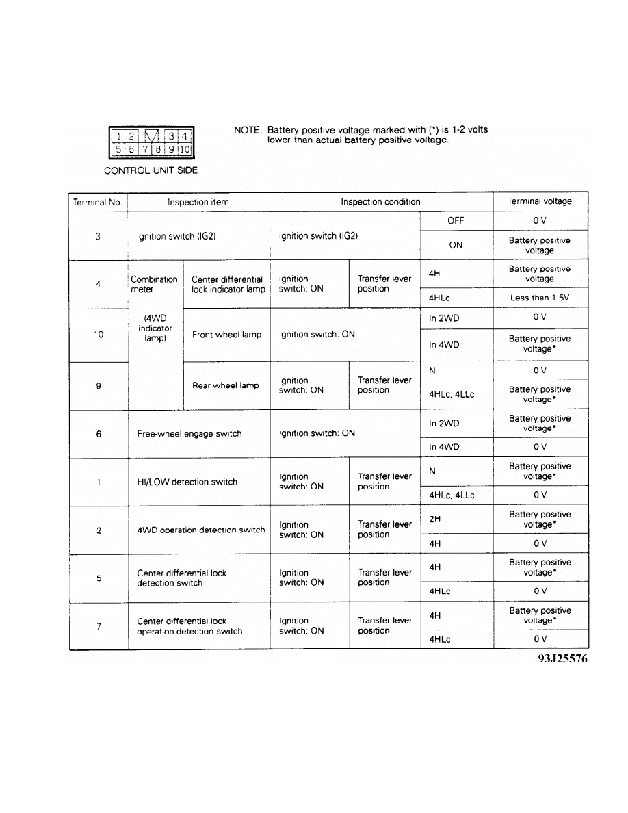
Fig. 1: 4WD Indicator Control Unit Testing (Montero)
Courtesy of Mitsubishi Motor Sales of America.
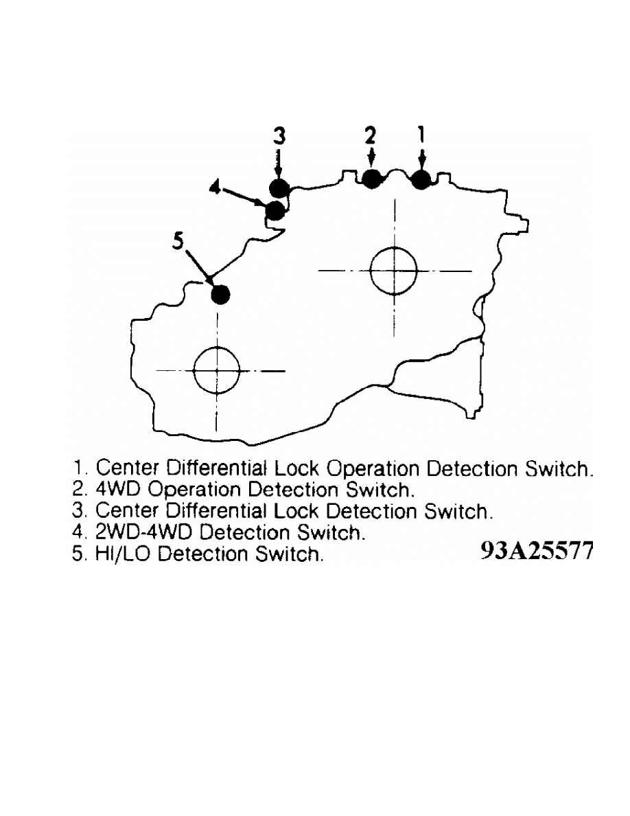
Fig. 2: Detection Switch Testing Locations (Montero)
Courtesy of Mitsubishi Motor Sales of America.
REMOVAL & INSTALLATION
Removal
1) Remove negative battery cable. Remove transfer case skid
plate (if equipped). Scribe alignment marks and remove both drive
shafts. Drain oil from transfer case. Disconnect wiring harness from
back-up light switch, all 4WD switches and any other electrical
connectors (if equipped).
2) Disconnect speedometer cable from drive. Unclip cable from
case. Place transfer case shifter in "2H" position and transmission in
Neutral. Remove 6 bolts holding control lever assembly. Remove control
lever assembly and gasket.
3) Remove select plunger bore plug at right side of case.
Remove select spring and plunger. Remove change shifter spring pin.
Remove change shifter. Remove transfer case mount. Remove 4 bolts and
2 nuts holding transfer case to adapter. Remove transfer case from
vehicle.
Installation
1) Position transmission shifter in Neutral and transfer case
lever in "2H" position. Install neutral return plungers and springs in
holes on top of adapter. Tighten plug until it is flush with adapter
surface. Cover plug threads with sealant.
2) Coat inside of change shifter with grease. Ensure change
shifter pin protrudes 1/8" above change shifter when installed. Mount
detent plunger spring and install plug (if equipped). To complete
installation, reverse removal procedure. Fill transfer case with API
GL-4 or higher 75W-90 or 75W-85W gear oil.
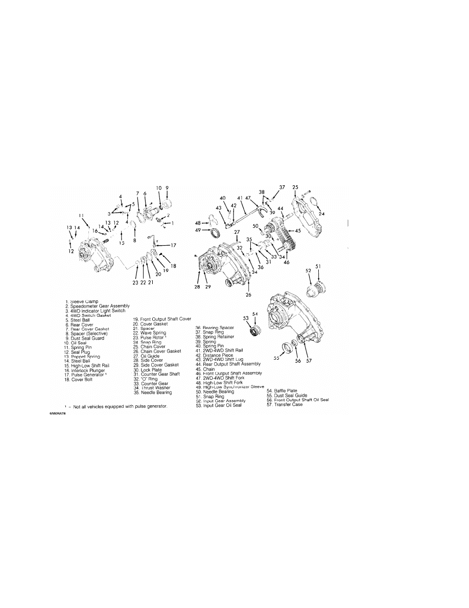
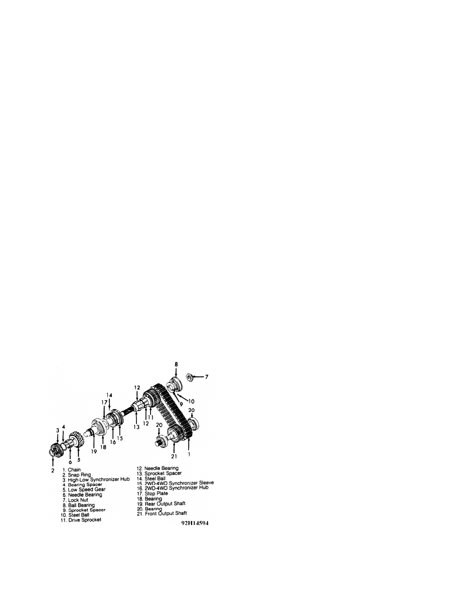
Fig. 3: Exploded View Of Transfer Case (Ram-50)
Courtesy of Mitsubishi Motor Sales of America.
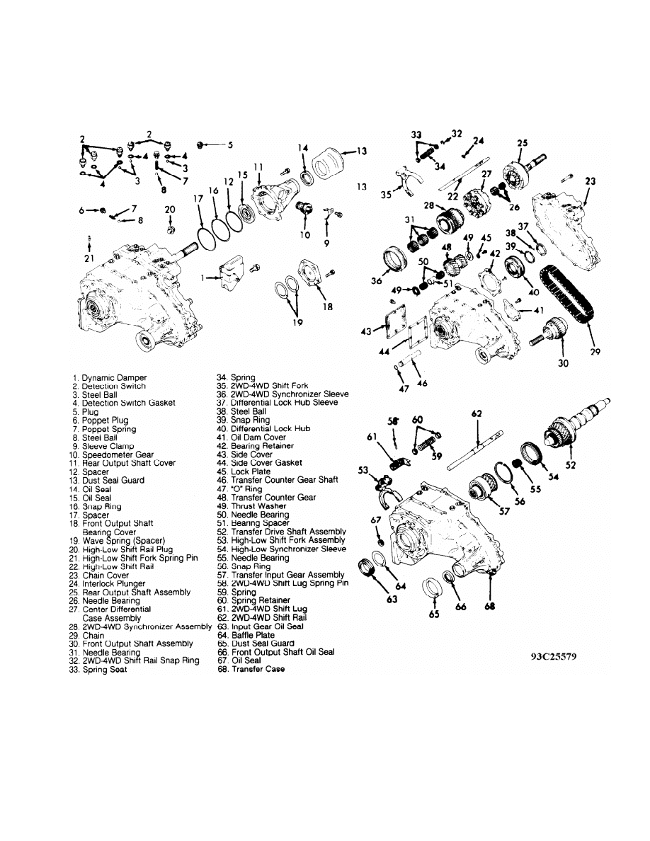
Fig. 4: Exploded View Of Transfer Case (Montero)
Courtesy of Mitsubishi Motor Sales of America.
TRANSFER CASE DISASSEMBLY
Disassembly (Ram-50)
1) Remove both 4WD indicator switches and steel balls. Remove
speedometer gear assembly. Remove output shaft cover, gasket, wave
spring and spacer. See Fig. 3. Remove rear cover, rear cover gasket
and spacer from chain cover. Drive roll pin out of high-low shift
fork.

2) Remove 2 seal plugs. Remove 2 poppet springs and steel
balls. Shift transfer case to "4WD" and pull high-low shift rail out,
in rear cover direction. Remove interlock plunger. Remove pulse
generator (if equipped), front output shaft cover and pulse rotor (if
equipped). Remove snap ring from rear bearing on output shaft. Remove
chain cover, oil guide and side cover. Remove countershaft locking
plate. Remove countershaft.
3) Remove countergear, 2 thrust washers, 2 needle bearings
and spacer through side cover opening. Remove snap ring, spring
retainers and spring from 2WD-4WD shift rail. Remove front output
shaft, rear output shaft and chain as assembly.
4) Remove 2WD-4WD shift fork and distance piece. Drive out
2WD-4WD shift rail spring pin. Remove 2WD-4WD shift rail and lug.
Remove high-low shift fork and high-low synchronizer sleeve. Remove
needle bearing and snap ring from input gear. Remove input gear
assembly.
5) If either control shaft or input gear oil seals are to be
replaced, drive out roll pin from transmission control change shifter.
Separate transfer case from adapter. See Fig. 3.
Disassembly (Montero)
1) Remove dynamic damper, 5 detection switches and 3 steel
balls. Remove poppet plug, spring and steel ball. Remove speedometer
gear assembly. Remove output shaft rear cover, spacers, dust seal
guard and oil seals. Front output shaft cover, wave spring and spacer
(if equipped).
2) Remove high-low shift rail plug and high-low shift fork
spring pin. Shift transfer case to "4WD". Remove rear cover and high-
low shift rail. Remove interlock plunger. Remove rear output shaft
(viscous coupling) assembly and center differential assembly. Remove
2WD-4WD synchronizer assembly, chain and front output shaft from
transmission as a unit. With White paint make match marks in grooves
of 2WD-4WD synchronizer in 3 places. With White paint make match marks
on spline projections of 2WD-4WD synchronizer sleeve in 3 places.
Refer to match marks during reassembly.
3) Remove snap ring, spring seat, spring, 2WD-4WD shift fork
and 2WD-4WD synchronizer sleeve. Remove differential lock hub, oil dam
cover and bearing retainer. Remove side cover and gasket. Remove
transfer counter gear shaft, transfer counter gear, thrust washer,
needle bearings and spacer. Remove transfer drive shaft assembly.
Remove high-low shift fork assembly and clutch sleeve. Remove transfer
input gear assembly.
4) Remove 2WD-4WD shift lug spring pin, spring, spring
retainer 2WD-4WD shift lug and shift rail. Remove input gear oil seal,
baffle plate, dust seal guard and front output shaft oil seal. See
Fig. 4.
COMPONENT DISASSEMBLY & REASSEMBLY
OUTPUT SHAFT ASSEMBLY (MONTERO)
Disassembly & Reassembly (Rear Shaft)
Remove snap ring and press ball bearing off without putting
pressure on vicious coupling. Remove viscous coupling. To install,
reverse removal procedure. When installing new snap ring, select
thickest ring that will fit into groove. Acceptable clearance is 0-.
003" (0-.08 mm).
Disassembly & Reassembly (Front Shaft)
Remove front bearing. Remove rear bearing. To install reverse
removal procedure.
OUTPUT SHAFT ASSEMBLY (RAM-50)
Disassembly
1) Remove snap ring from rear of output shaft. Remove high-
low synchronizer hub by hand or when low speed gear is pressed off.
Remove bearing spacer and needle bearing. Remove staking from lock nut
on rear output shaft. See Fig. 5. Remove lock nut. Remove ball bearing
from below lock nut. Remove sprocket spacer and steel ball.
2) Remove drive sprocket, 2 needle bearings, sprocket sleeve
and steel ball. Remove 2WD-4WD synchronizer sleeve, hub, stopper plate
and ball bearing.
Reassembly
1) Press ball bearing and stopper plate on front output
shaft, pushing against inner race. After fitting, ensure bearing
rotates smoothly. Install 2WD-4WD synchronizer hub and sleeve. Ensure
hub and sleeve face correct direction. Install steel ball (for
sprocket sleeve positioning) on rear output shaft. Install sprocket
sleeve.
2) Install 2 needle bearings on outer circumference of
sprocket sleeve. Install drive sprocket. Install steel ball and
sprocket spacer. Install ball bearing (press may not be needed as
bearing may be loose). Check for smooth rotation.
3) Tighten sprocket retaining lock nut to specification. See
the TORQUE SPECIFICATIONS table. Stake lock nut with punch. After lock
nut is tightened, ensure drive sprocket rotates smoothly. Install
needle bearing, thrust washer and low speed gear on rear of rear
output shaft.
4) Install needle bearing, thrust washer and low speed gear
on rear output shaft. Mount high-low synchronizer hub. Ensure hub
faces correct direction.
5) Mount high-low synchronizer hub snap ring on front end of
rear output shaft. Selective fit snap rings are available in 5
thicknesses. Use thickest snap ring that will fit into output shaft
groove. Acceptable clearance is 0-.003" (0-.08 mm). See Fig. 5.
Fig. 5: Exploded View Of Output Shaft Assembly (Ram-50)
Courtesy of Mitsubishi Motor Sales of America.
TRANSFER DRIVE SHAFT (MONTERO)
Disassembly & Reassembly
Remove snap ring, high-low synchronizer hub and low speed
gear. Remove bearing spacer, needle bearing and ball bearing. To
assemble, reverse disassembly procedure. Use thickest snap ring that
will fit into output shaft groove. Acceptable clearance is 0-.003" (0-
.08 mm). See Fig. 4.
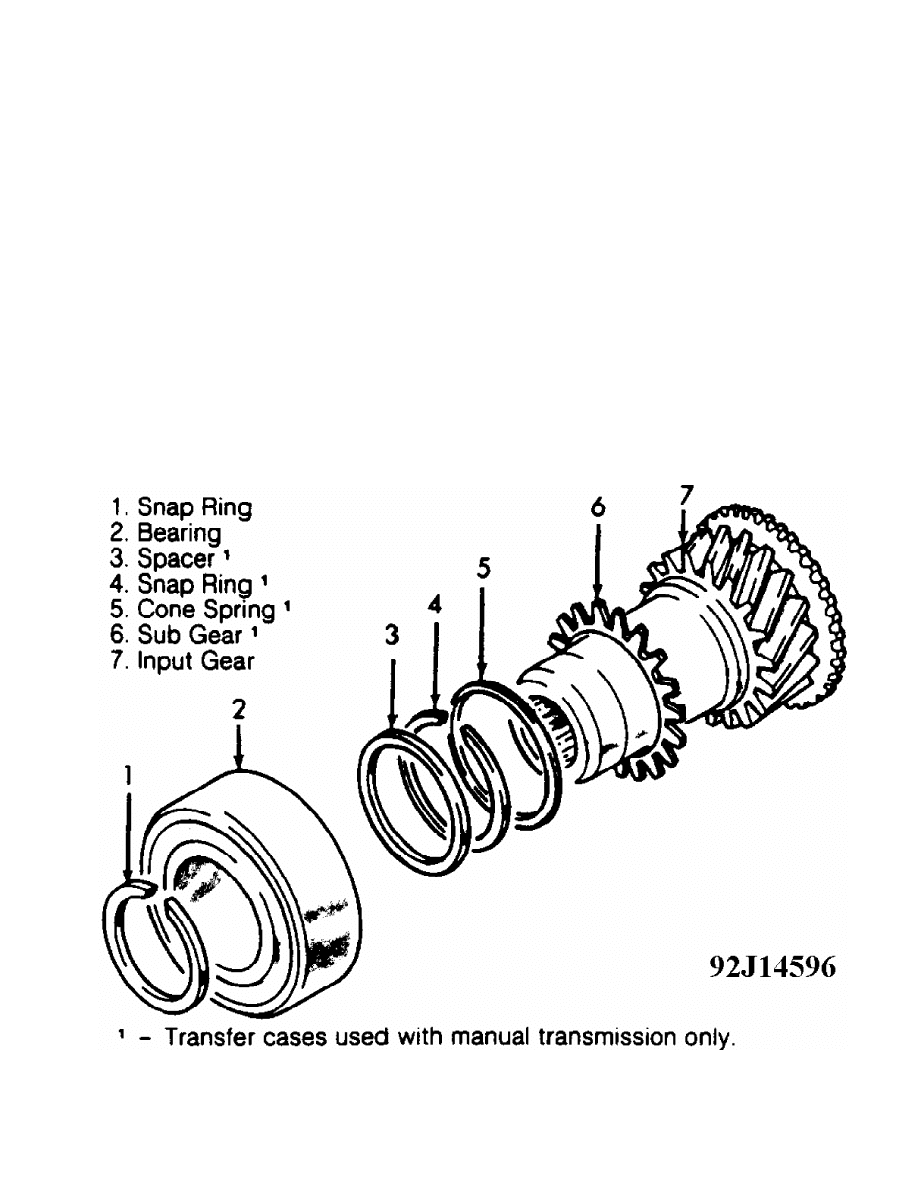
INPUT SHAFT ASSEMBLY (RAM-50)
Disassembly & Reassembly
1) Remove snap ring from input shaft. Support bearing in
press. Press input shaft out to remove bearing.
2) On manual transmission models, remove spacer and snap ring
from below bearing. Remove cone spring and sub gear. See Fig. 6. For
reassembly, reverse disassembly procedures.
3) Press bearing into input shaft, pushing against inner
race. After fitting, ensure bearing rotates smoothly. Fit snap ring
over front end of input shaft. Snap rings are available in selective
thicknesses. Select thickest snap ring that will fit in groove.
Fig. 6: Exploded View Of Input Shaft Assembly (Ram-50 - Manual
Shown, Automatic Similar)
Courtesy of Mitsubishi Motor Sales of America.
CENTER DIFFERENTIAL CASE (MONTERO)
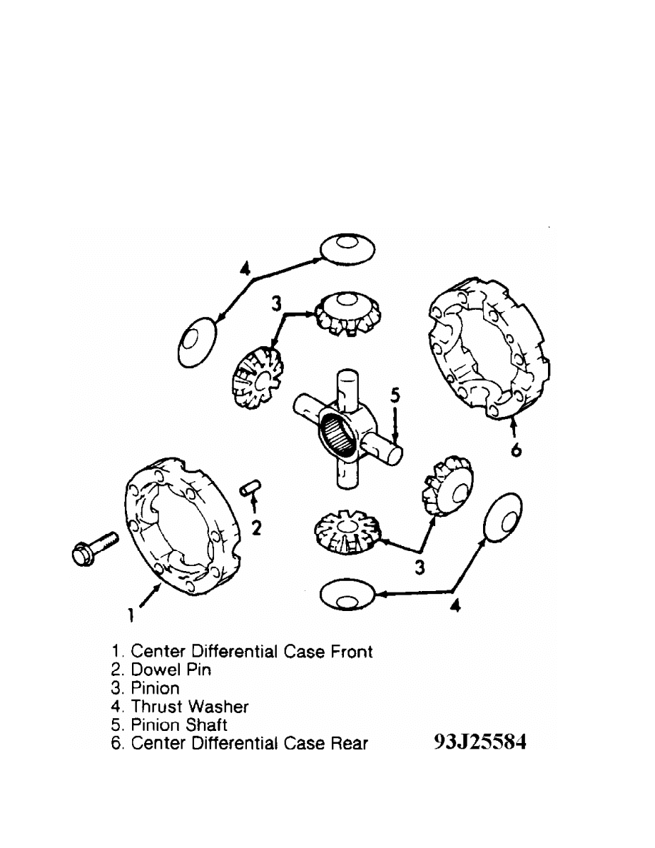
Disassembly & Reassembly
Separate center differential case front from rear case.
Remove pinion shaft, pinions, thrust washers and dowel pins. Inspect
for excessive wear and replace parts as needed. Align dowel pins and
match marks on outer case circumferences. Assemble front and rear
center differential cases. See the TORQUE SPECIFICATIONS table. Also,
see Fig. 7.
Fig. 7: Exploded View Of Center Differential (Montero)
Courtesy of Mitsubishi Motor Sales of America.
2WD-4WD SYNCHRONIZER (MONTERO)
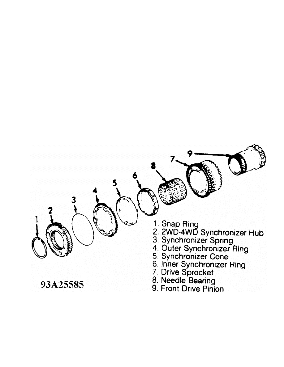
Disassembly
Remove snap ring, 2WD-4WD synchronizer hub and synchronizer
spring. Remove outer synchronizer ring, synchronizer cone and inner
synchronizer ring. Remove drive sprocket and needle bearing from front
drive pinion. Inspect inner and outer synchronizer rings and cone for
excessive wear. Install inner and outer synchronizer rings and cone
onto drive sprocket. Measure distance between drive sprocket and outer
synchronizer. If distance is less than .0118" (.300 mm) replace
synchronizer parts as a set.
Reassembly
Install drive sprocket and needle bearing onto front drive
pinion. Apply transfer case gear oil to contacting surfaces of inner
and outer synchronizer rings and synchronizer cone. Install inner and
outer synchronizer rings and synchronizer cone. Install synchronizer
spring, 2WD-4WD synchronizer hub and snap ring to complete assembly.
When installing new snap ring, select thickest ring that will fit into
groove. Acceptable snap ring clearance is 0-.003" (0-.080 mm).
Fig. 8: Exploded View Of 2WD-4WD Synchronizer (Montero)
Courtesy of Mitsubishi Motor Sales of America.
TRANSFER CASE REASSEMBLY
NOTE: ALWAYS replace all gaskets, oil seals, snap rings and spring
pins with new parts. Coat both sides of gaskets and bolt
threads with sealant. Lubricate all sliding and rotating
parts with transfer case gear oil before assembling.
Reassembly (Ram-50)

1) Install input gear and front output shaft oil seals into
transfer case housing. Pack grease between lips of seals and press
seal circumference uniformly.
2) Install input gear assembly in transfer case. See Figs. 3
and 6. Input gear assembly snap ring is available in selective
thicknesses. Use thickest snap ring that will fit into input shaft
groove. Allowed snap ring clearance is 0-.0024" (0-.060 mm).
3) Insert needle bearing onto rear output shaft assembly.
Install high-low synchronizer sleeve and shift fork. Install 2WD-4WD
shift fork. Engage chain securely on front and rear output shaft
sprockets. Assemble 2WD-4WD synchronizer sleeve with 2WD-4WD shift
fork. Install assembly over 2WD-4WD shift rail. Install front and rear
output shafts with chain as an assembly.
4) Install 2WD-4WD shift lug, distance piece, 2WD-4WD shift
rail and spring pin. Ensure slit in spring pin is in line with 2WD-4WD
shift rail. Install 2 spring retainers with spring on 2WD-4WD shift
rail. Install snap ring to end of 2WD-4WD shift rail. See Fig. 3.
5) Insert 2 needle bearings and spacer into countergear.
Install one thrust washer at each end of countergear. Ensure tab on
thrust washers fits into groove of transfer case. Install countergear
shaft assembly with "O" ring.
6) Install side cover and gasket. Install oil guide. Apply
sealant to both sides of gasket and install gasket and chain cover.
Ensure oil guide end fits into chain cover opening. Fit snap ring into
groove of rear bearing on rear output shaft. Tighten bolts to
specification. See TORQUE SPECIFICATIONS.
7) Install interlock plunger. Shift 2WD-4WD shift rail to 4WD
position. Install high-low shift rail through high-low shift fork in
case. Install 2 poppet balls and springs. Install seal plugs. When
installing poppet springs, smaller end must be toward ball.
8) On models with pulse generator, install pulse rotor, wave
spring and spacer. Measure protrusion "A" of front output shaft rear
bearing and recess "B" of cover and calculate clearance. See Fig. 9.
If clearance is greater than .079" (2.0 mm), select and install spacer
to bring clearance within specification. If clearance is less than .
079" (2.0 mm), use wave spring alone. Apply sealant to both sides of
gasket and install gasket and cover. Install pulse generator (if
equipped).
9) On all models, align high-low shift fork and shift rail
spring holes and drive in roll pin with punch. Roll pin should be
installed with slit on center line of shift rail. Install wave spring
on rear of rear output shaft bearing. Apply sealant to both sides of
rear cover gasket. Install gasket and cover.
10) Check output shaft end play. Measure protrusion "A" of
rear output shaft rear bearing and recess "B" of cover and calculate
clearance. Ensure end play is 0-.004" (0-.10 mm). Apply sealant to
both sides of gasket and install gasket and cover. See Fig. 9.
11) Install speedometer sleeve assembly in rear cover. Align
match mark on speedometer sleeve assembly in rear cover. See Fig. 10.
Align match mark on speedometer sleeve with mark on case according to
number of teeth on speedometer driven gear. Install speedometer driven
gear sleeve clamp and tighten bolt to specification. Install both 4WD
indicator light switches with steel balls. See TORQUE SPECIFICATIONS.
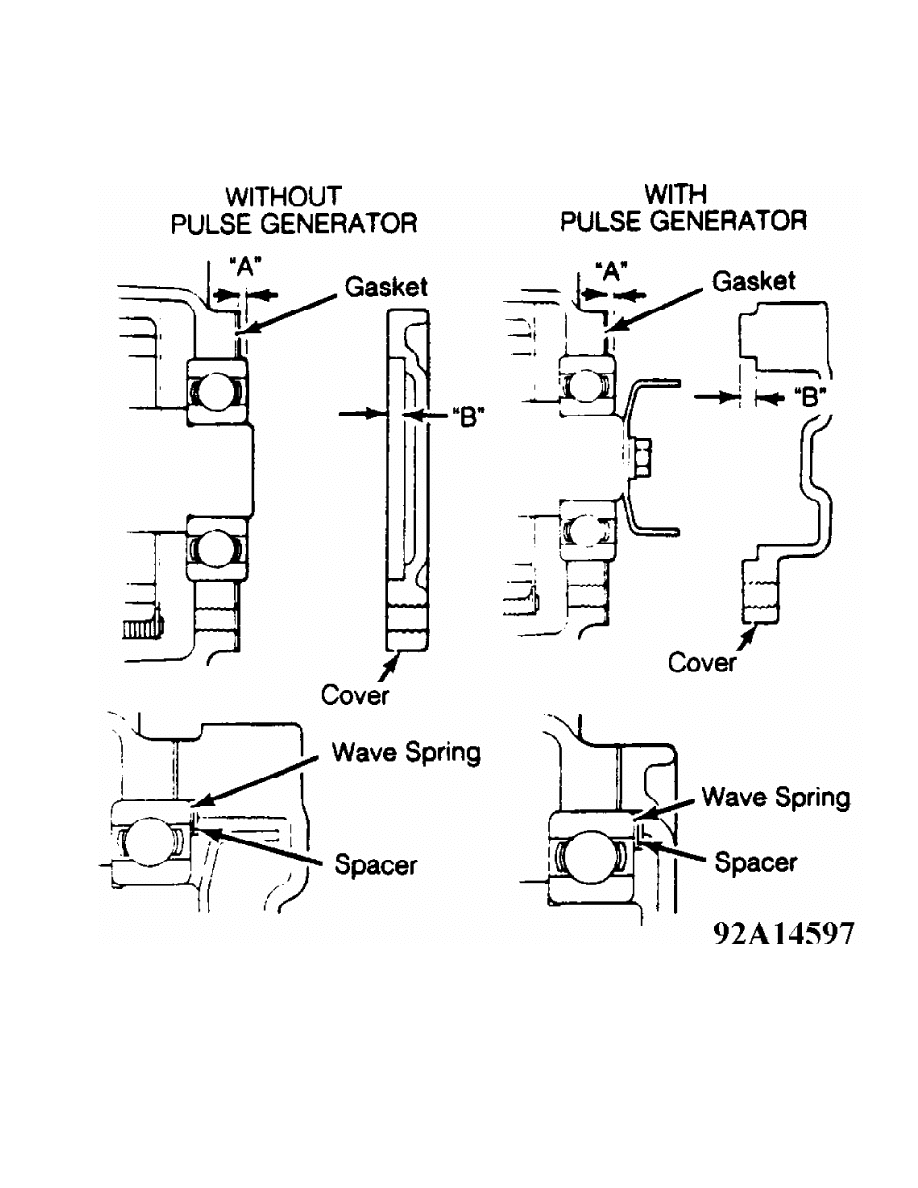
Fig. 9: Measuring Rear Output Shaft Bearing Clearance (Ram-50)
Courtesy of Mitsubishi Motor Sales of America.
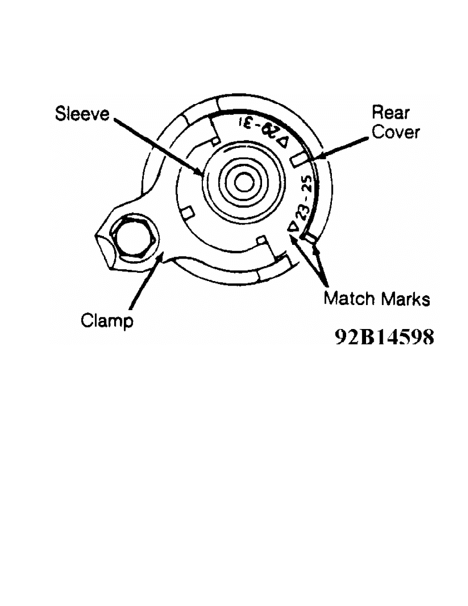
Fig. 10: Aligning Speedometer Sleeve
Courtesy of Mitsubishi Motor Sales of America.
Reassembly (Montero)
1) Install input gear and front output shaft oil seals into
transfer case housing. Install transfer input gear assembly baffle
plate and input gear seal. Pack grease between lips of seals and press
seal circumference uniformly.
2) Install 2WD-4WD shift lug into transfer case. Install
spring retainer and spring to shift rail and install into shift lug.
Press on shift rail to align spring pin holes in shift rail and shift
lug. While holding shift rail, tap spring pin into place with slit
facing center of shift rail.
3) Install transfer input gear assembly and snap ring. Select
thickest snap ring that will fit into groove. Allowed snap ring
clearance is 0-.0024" (0-.060 mm). Insert needle bearing onto transfer
drive shaft assembly. Install high-low synchronizer sleeve and shift
fork assembly. Install transfer drive shaft assembly.
4) Install transfer countergear shaft thrust washers, needle
bearings, bearing spacer and transfer countergear. Install one thrust
washer at each end of transfer countergear. Ensure tab on thrust
washers fits into groove of transfer case. Install counter gear shaft
from transmission case side so lock plate groove is aligned with lock
plate. Install lock plate. Install side cover and gasket.
5) Install bearing retainer. If reusing bearing retainer
bolts, apply Locking Adhesive (3M 4170 Stud Lock) to threads. Install
oil dam cover. Install differential lock hub, snap ring, steel ball
and sleeve. Select thickest snap ring that will fit into groove.
Allowed snap ring clearance is 0-.003" (0-.08 mm). Install 2WD-4WD
synchronizer sleeve, 2WD-4WD shift fork, spring, spring seat and 2WD-

4WD shift rail snap ring.
6) Assemble front output shaft assembly, chain and 2WD-4WD
synchronizer assembly. Align match marks made during disassembly. Link
chain tightly onto 2WD-4WD synchronizer and front output shaft
sprockets. Install both sprockets and chain to transfer case at same
time, while keeping them as far apart as possible.
7) Install center differential case assembly, rear output
shaft assembly needle bearings and rear output shaft assembly. Install
interlock plunger so it does not interfere with 2WD-4WD shift rail.
Evenly apply sealant to chain cover and install chain cover.
8) Install high-low shift rail through high-low shift rail
hole into shift fork. Align spring pin holes in high-low shift rail
and shift fork. Tap in spring pin so slit is facing shift rail shaft
center. Install and tighten high-low shift rail plug to specification.
See TORQUE SPECIFICATIONS.
9) Before installing front output shaft cover, measure
protrusion "A" of front output shaft rear bearing and recess "B" of
cover and calculate clearance. See Fig. 11. If clearance is greater
than .079" (2.00 mm), select and install spacer to bring clearance
within specification. If clearance is less than .079" (2.00 mm), use
wave spring alone. Apply sealant to both sides of gasket and install
gasket and cover. Apply Locking Adhesive (3M 4170 Stud Lock) to bolts
and tighten to specification. See TORQUE SPECIFICATIONS.
Fig. 11: Measuring Rear Output Shaft Bearing Clearance (Montero)
Courtesy of Mitsubishi Motor Sales of America.
10) Install rear output shaft ball bearing snap ring. Measure
clearance between chain cover and snap ring. Add .0008-.0039" (.02-.10

mm) to clearance measured and install spacer of similar thickness.
Install rear output shaft oil seal (apply grease to lip of seal).
Install rear cover oil seal (apply grease to lip of seal).
11) Before installing rear cover, snap ring and spacer
thicknesses must be determined. Measure protrusion of rear output
shaft bearing. Measure inset of both stages of cover. Subtract inset
recess from rear bearing protrusion. Select a snap ring which adjusts
difference between inset recess and rear bearing protrusion, and
spacer thickness to 0-.004" (0-0.10 mm). Evenly apply sealant to rear
cover and install cover. Tighten bolts to specification. Refer to the
TORQUE SPECIFICATIONS table.
12) Install speedometer gear, ensuring mating marks match
according to number of gear teeth. Install speedometer gear sleeve
clamp and tighten bolt to specification. See Fig. 10.
13) Apply sealant to poppet plug threads. Install poppet
steel balls, springs and poppet plugs and tighten to specification.
Install detection switches, steel balls and gaskets. See Fig. 12.
Install dynamic damper and tighten bolts to specification.
Fig. 12: Installation Of Detection Switches (Montero)
Courtesy of Mitsubishi Motor Sales of America.
TORQUE SPECIFICATIONS

TORQUE SPECIFICATIONS TABLE
Application Ft. Lbs. (N.m)
Adapter-To-Transfer Bearing Retainer ......... ( 1) 14 (19)
Case Nuts & Bolts .......................... 22-31 (30-42)
Center Differential Case Bolts ................... 48 (65)
Chain Cover Bolt ........................... 22-31 (30-42)
Detection Switch ............................. ( 1) 27 (36)
Drain Plug ................................. 22-26 (30-35)
Dynamic Damper ................................... 52 (70)
High-Low Shift Rail Plug ..................... ( 1) 24 (33)
Interlock Plunger Plug ................. ( 1) 22-26 (30-35)
Lock Plate Bolts ........................... 11-16 (15-22)
Oil Dam Cover ................................ ( 1) 14 (19)
Oil Filler Plug ............................ 22-26 (30-35)
Output Shaft Cover Bolt .................... 11-16 (15-22)
Poppet Plug .................................. ( 1) 27 (36)
Pulse Rotor Bolt ....................... ( 2) 11-16 (15-22)
Rear Cover Bolt ............................ 11-16 (15-22)
Rear Output Shaft Lock Nut ............... 74-96 (100-130)
Seal Plug .............................. ( 2) 22-31 (30-42)
Speedometer Sleeve Clamp Bolt .............. 11-16 (15-22)
4WD Indicator Light Switch ................... ( 2) 22 (33)
INCH Lbs. (N.m)
Pulse Generator Bolt .................. ( 2) 89-106 (10-12)
Side Cover Bolt ............................. 71-89 (8-10)
(1) - Montero.
(2) - Ram-50.
WIRING DIAGRAMS
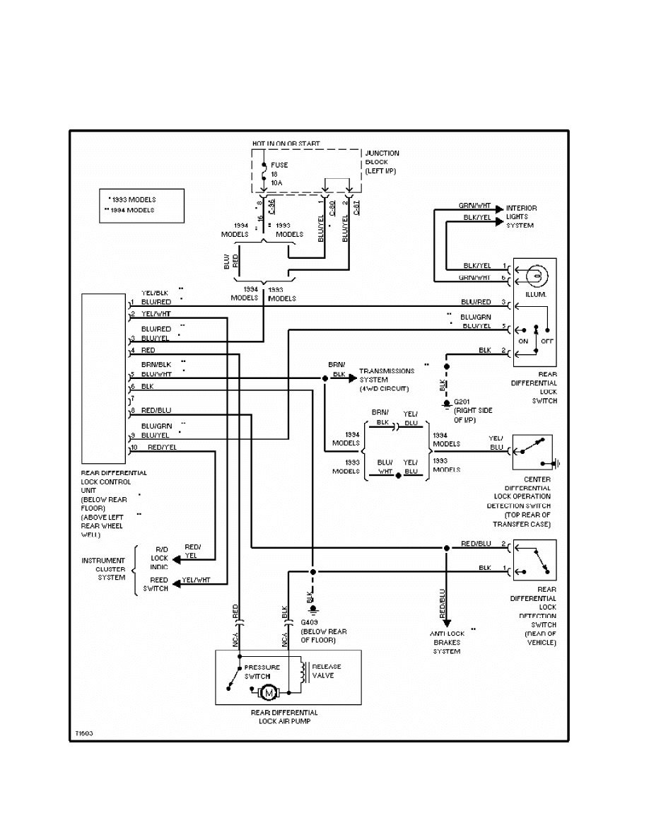
Fig. 13: Rear Differential Lock Circuit (Montero)

Fig. 14: Active Trac 4WD Circuit (Montero)
Wyszukiwarka
Podobne podstrony:
2810 Transfer case, checking & correcting fluid level
2801 Transfer case fluid change
Transformation A Bold Case for Unconventional Warfare
Production of benzaldehyde, a case study in a possible industrial application of phase transfer cata
T7 Transformacja układu odniesienia
11 BIOCHEMIA horyzontalny transfer genów
Transformacje91
5 Algorytmy wyznaczania dyskretnej transformaty Fouriera (CPS)
11Tor z transformatoramiid 13123 ppt
Transformacje2
20 H16 POST TRANSFUSION COMPLICATIONS KD 1st part PL
Immunologia Transfuzjologiczna1[1]
3 Rodzaje jednorodnych transformacji stosowanych w kinematy
Transfer sk adki US
Badanie transformatora
Efficient VLSI architectures for the biorthogonal wavelet transform by filter bank and lifting sc
6 Miedzynarodowy transfer wyklad 11 04 2012 id 43355
więcej podobnych podstron