3009Z–03
–
DRIVE SHAFT / PROPELLER SHAFT
DRIVE SHAFT, PROPELLER SHAFT, AXLE
30–1
1266
Author:
Date:
2004 COROLLA (RM1037U)
DRIVE SHAFT, PROPELLER SHAFT, AXLE
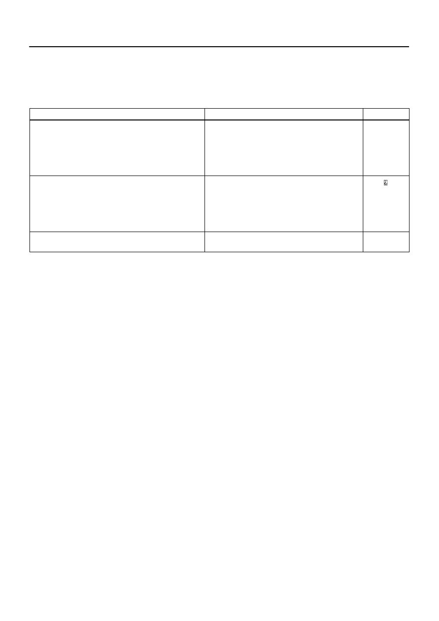
PROBLEM SYMPTOMS TABLE
Use the table below to help you find the cause of the problem. The numbers indicate the priority of
the likely cause of the problem. Check each part in order. If necessary, replace these parts.
Symptom
Suspect Area
See page
Wander
5. Wheel alignment
6. Steering linkage (Loosen or worn)
7. Hub bearing (Worn)
8. Stabilizer bar
26–5
27–3
51–18
30–17
30–24
26–19
Front wheel shimmy
1. Wheel balance
2. Shock absorber
3. Suspension arm lower (Worn)
4. Coil spring
5. Hub bearing (Worn)
26–8
26–13
26–8
30–17
30–24
Noise (Drive shaft)
1. Inbord joint (Worn)
2. Outbord joint (Worn)
30–6
30–6
300A0–02
D26919
D26920
D26921
30–2
–
DRIVE SHAFT / PROPELLER SHAFT
DRIVE SHAFT, PROPELLER SHAFT, AXLE
1267
Author:
Date:
2004 COROLLA (RM1037U)
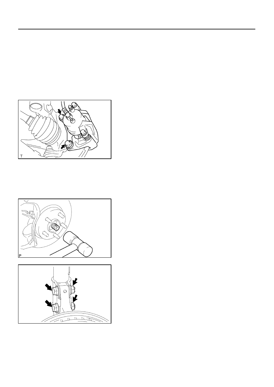
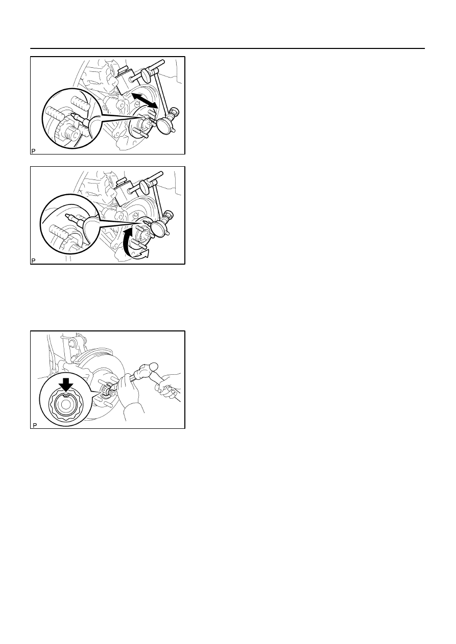
ON–VEHICLE INSPECTION
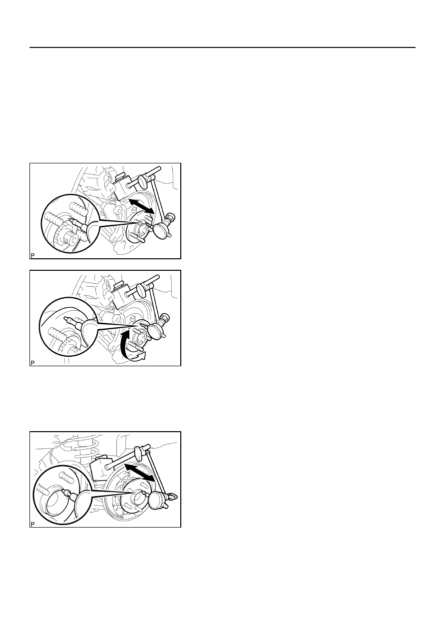
1.
INSPECT FRONT AXLE HUB BEARING
(a)
Remove the front wheel.
(b)
Separate the front disc brake caliper assy
(See page
30–17
).
(c)
Remove the front disc.
(d)
Inspect the bearing backlash.
(1)
Using a dial indicator, check the backlash near the
center of the axle hub.
Maximum: 0.05 mm (0.0020 in.)
If the backlash exceeds the maximum, replace the front axle
hub bearing.
(e)
Inspect the axle hub deviation.
(1)
Using a dial indicator, check the deviation at the sur-
face of the axle hub outside the hub bolt.
Maximum: 0.05 mm (0.0020 in.)
If the backlash exceeds the maximum, replace the front axle
hub sub–assy.
(f)
Install the front disc.
(g)
Install the front disc brake caliper assy
(See page
30–17
).
(h)
Install the front wheel.
Torque: 103 N
⋅
m (1,050 kgf
⋅
cm, 76 ft
⋅
lbf)
2.
INSPECT REAR AXLE HUB BEARING
(a)
Remove the rear wheel.
(b)
Remove rear brake drum sub–assy.
(c)
Inspect the bearing backlash.
(1)
Set a dial indicator near the center of the axle hub
and check the backlash in the bearing shaft sirec-
tion.
Maximum: 0.05 mm (0.0020 in.)
If the backlash exceeds the maximum, replace the rear axle hub
& bearing assy.
D26922
–
DRIVE SHAFT / PROPELLER SHAFT
DRIVE SHAFT, PROPELLER SHAFT, AXLE
30–3
1268
Author:
Date:
2004 COROLLA (RM1037U)
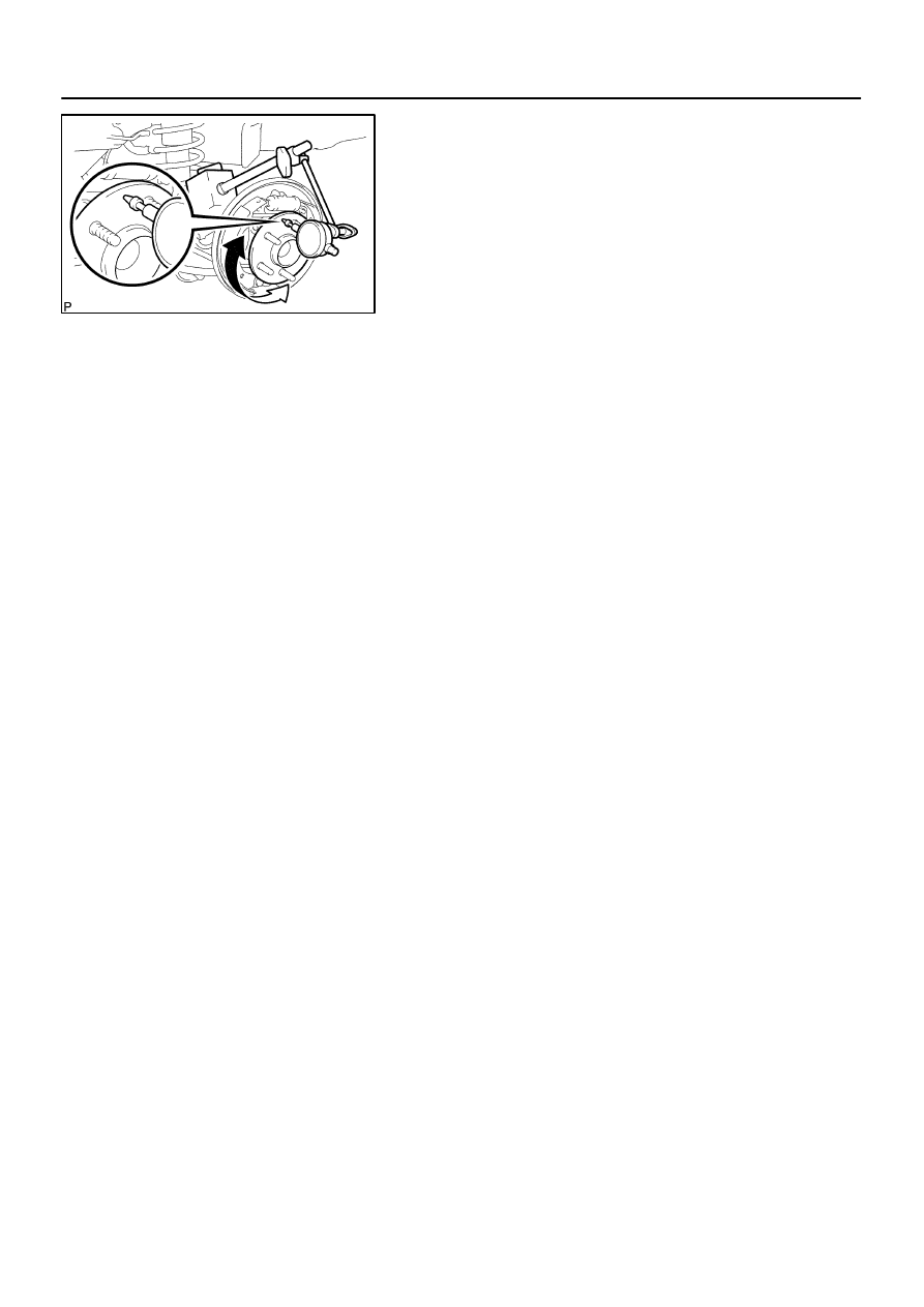
(d)
Inspect the axle hub deviation.
(1)
Using a dial indicator, check the deviation at the sur-
face of the axle hub outside the hub bolt.
Maximum: 0.07 mm (0.0028 in.)
If the backlash exceeds the maximum, replace the rear axle hub
& bearing assy.
(e)
Install the rear brake drum sub–assy.
(f)
Install the rear wheel.
Torque: 103 N
⋅
m (1,050 kgf
⋅
cm, 76 ft
⋅
lbf)
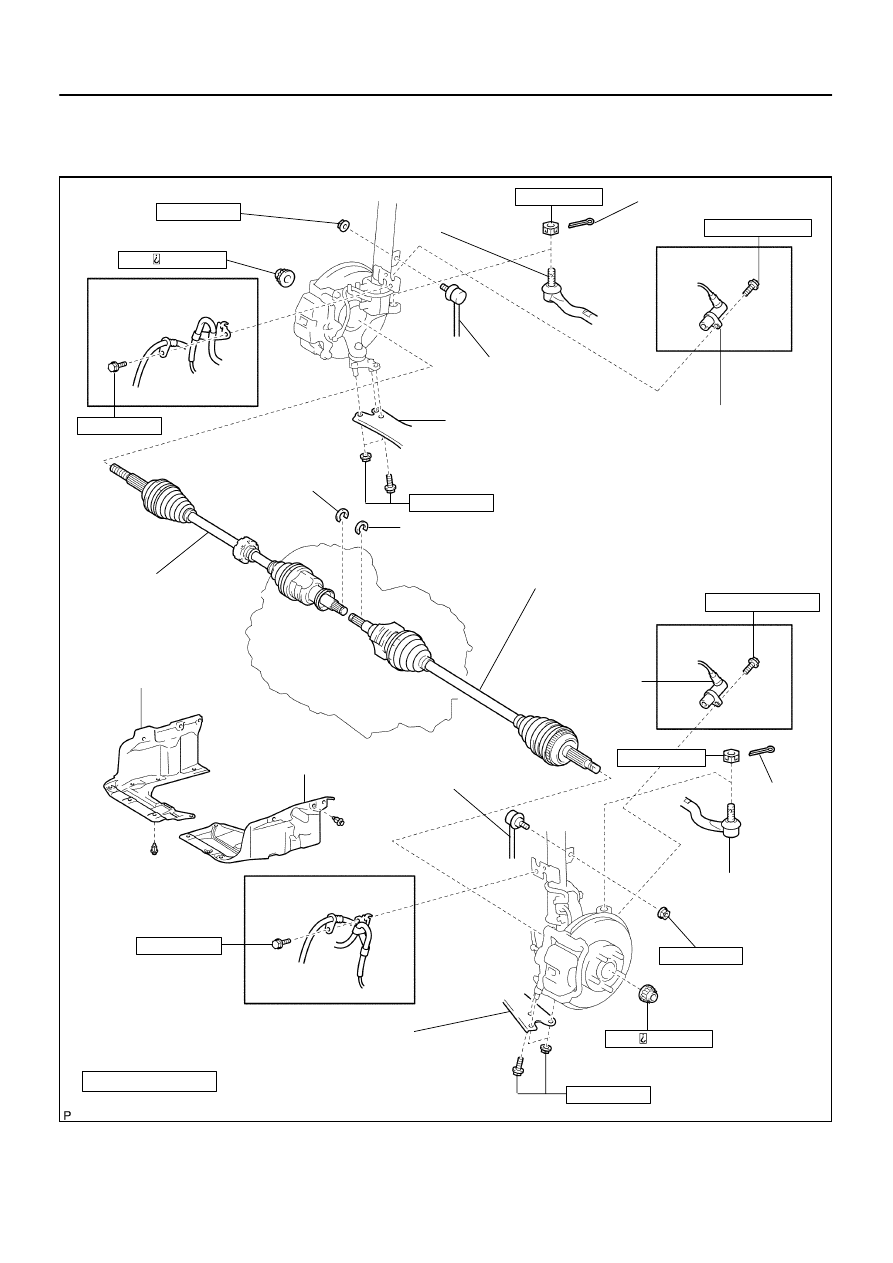
300A1–02
D26923
Speed Sensor
Front LH
Front Drive Shaft LH Hole Snap Ring
Non–reusable parts
Front Drive Shaft Assy RH
Cotter Pin
Front Axle Hub RH Nut
216 ( ,200, 159)
Tie Rod End
Sub–assy RH
Speed Sensor Front RH
Front Suspension Arm
Sub–assy No.1 LH
N·m (kgf·cm, ft·lbf)
: Specified torque
89 (908, 66)
Engine Under Cover LH
216 ( ,200, 159)
Front Drive Shaft Assy LH
Front Drive Shaft
RH Hole Snap Ring
Engine Under Cover RH
Front Stabilizer
Link Assy RH
Front Stabilizer
Link Assy LH
Front Suspension Arm
Sub–assy No.1 RH
29 (296, 21)
89 (908, 66)
8.0 (82, 71 in.·lbf)
w/ ABS:
49 (500, 36)
w/ ABS:
8.0 (82, 71 in.·lbf)
49 (500, 36)
Cotter Pin
Tie Rod End
Sub–assy LH
74 (755, 55)
74 (755, 55)
w/ ABS:
w/ ABS:
29 (296, 21)
Front Axle Hub LH Nut
30–4
–
DRIVE SHAFT / PROPELLER SHAFT
FRONT DRIVE SHAFT
1269
Author:
Date:
2004 COROLLA (RM1037U)
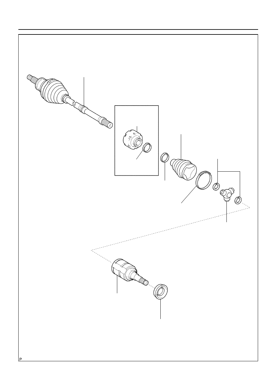
FRONT DRIVE SHAFT
COMPONENTS
D26924
Drive Shaft
Damper Setting
Clamp
Non–reusable parts
Front Drive Outboard
Joint Assy LH
Front Axle Inboard Joint
Boot LH No.2 Clamp
Inboard Joint Boot
Front Axle Inboard
Joint Boot LH Clamp
Front Drive Inner Shaft
Inner LH Shaft Snap Ring
Drive Shaft
Damper
RH:
Front Drive Shaft
Dust Cover LH
Front Axle Inboard Joint
Sub–assy LH
Tripod Joint Assy
–
DRIVE SHAFT / PROPELLER SHAFT
FRONT DRIVE SHAFT
30–5
1270
Author:
Date:
2004 COROLLA (RM1037U)
300AS–02
D27404
SST
F13686
Turn
Hold
C80291
C80292
30–6
–
DRIVE SHAFT / PROPELLER SHAFT
FRONT DRIVE SHAFT
1271
Author:
Date:
2004 COROLLA (RM1037U)
OVERHAUL
HINT:
COMPONENTS: See page
30–4
1.
DRAIN MANUAL TRANSAXLE OIL (M/T TRANSAXLE)
Torque: 39.2 N
⋅
m (400 kgf
⋅
cm, 29 ft
⋅
lbf)
2.
DRAIN AUTOMATIC TRANSAXLE FLUID (A/T TRANSAXLE)
Torque: 17.5 N
⋅
m (178 kgf
⋅
cm, 13 ft
⋅
lbf)
3.
REMOVE FRONT WHEEL
4.
REMOVE ENGINE UNDER COVER LH
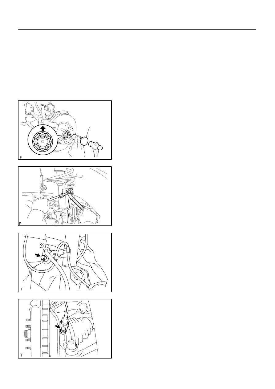
5.
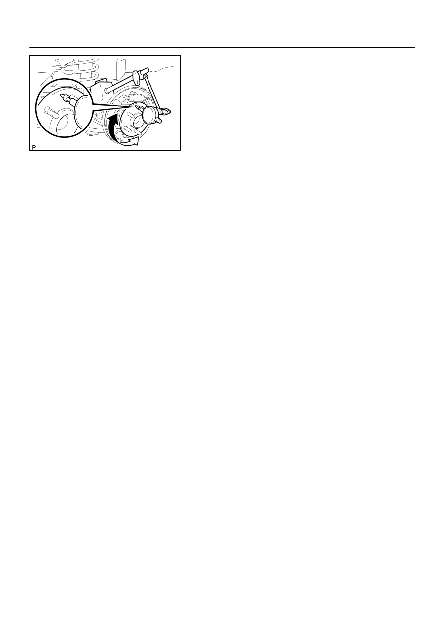
REMOVE FRONT AXLE HUB LH NUT
(a)
Using SST and a hammer, unstake the staked part of the
hub LH nut.
SST
09930–00010
(b)
While applying the brakes, remove the hub LH nut.
NOTICE:
Loosen the staked part of the nut completely, otherwise the
screw of the drive shaft may be damaged.
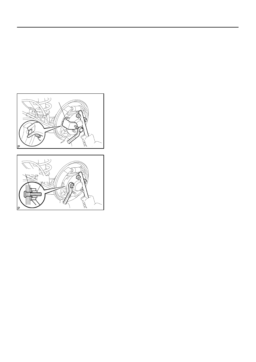
6.
SEPARATE FRONT STABILIZER LINK ASSY LH
(a)
Remove the nut, separate the front stabilizer link assy LH
from the shock absorber assy front LH.
HINT:
If the ball joint turns together with the nut, use a hexagon
wrench (6 mm) to hold the stud.
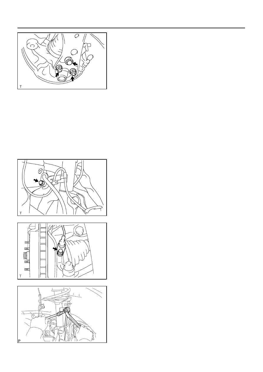
7.
SEPARATE SPEED SENSOR FRONT LH (W/ ABS)
(a)
Remove the bolt, separate the speed sensor front LH and
flexible hose from the shock absorber assy front LH.
(b)
Remove the bolt, separate the speed sensor front LH
from the steering knuckle.
F40217
SST
Turn
Hold
C80293
D27403
D27461
SST
(A)
(B)
–
DRIVE SHAFT / PROPELLER SHAFT
FRONT DRIVE SHAFT
30–7
1272
Author:
Date:
2004 COROLLA (RM1037U)
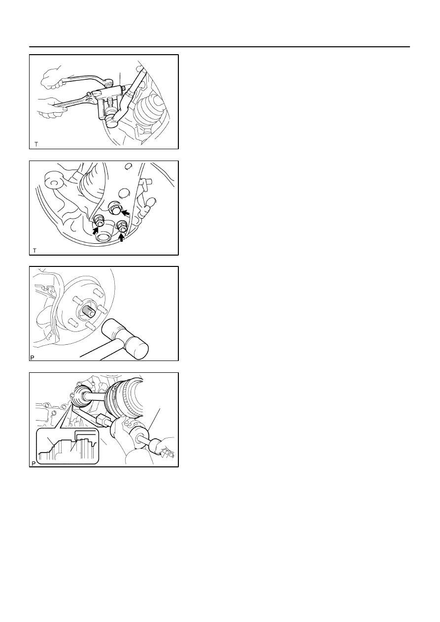
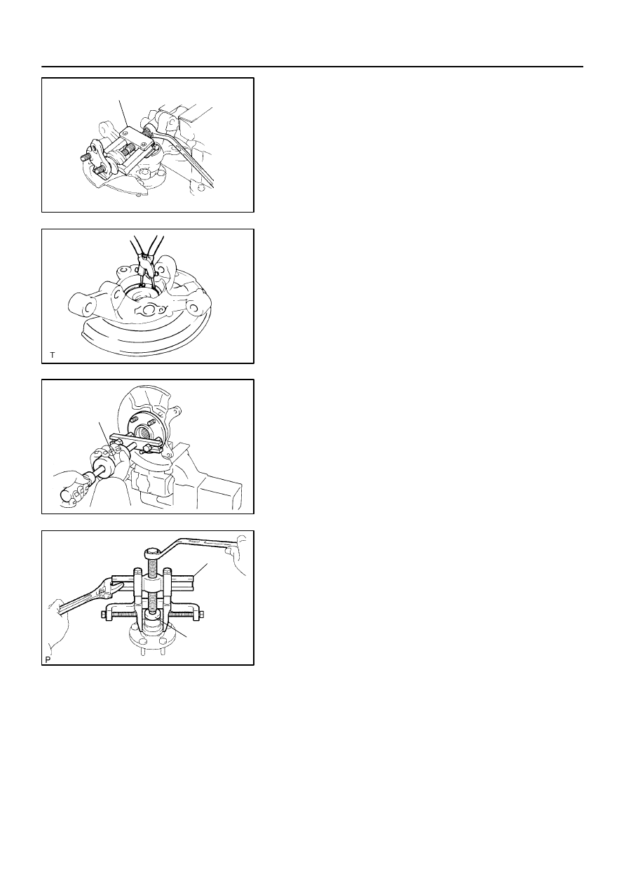
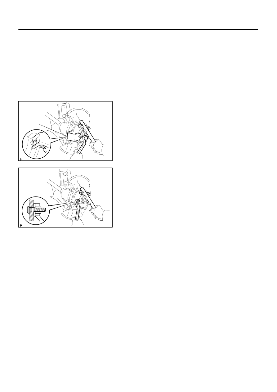
8.
SEPARATE TIE ROD END SUB–ASSY LH
(a)
Remove the cotter pin and nut.
(b)
Using SST, separate the tie rod end sub–assy LH from the
steering knuckle.
SST
09628–62011
9.
SEPARATE FRONT SUSPENSION ARM SUB–ASSY
LOWER NO.1 LH
(a)
Remove a bolt and 2 nuts, separate the front suspension
arm sub–assy lower No.1 LH from the lower ball joint.
10.
SEPARATE FRONT AXLE ASSY LH
(a)
Using a plastic hammer, separate the front drive shaft
assy LH from the front axle assy LH.
NOTICE:
Be careful not to damage the boot.
w/ ABS:
Be careful not to damage the speed sensor rotor.
11.
REMOVE FRONT DRIVE SHAFT ASSY LH
(a)
Using SST, remove the front drive shaft assy LH.
SST
09520–01010, 09520–24010 (09520–32040)
NOTICE:
Be careful not to damage the dust cover and oil seal.
HINT:
In case of not being able to remove the drive shaft at the posi-
tion of the illustration (A), hook the claw of SST to the position
of the illustration (B), remove it.
12.
REMOVE FRONT DRIVE SHAFT ASSY RH
HINT:
Remove the RH side by the same procedures as the LH side.
NOTICE:
Be careful not to damage the dust cover and oil seal.
F40218
SST
N00191
D27501
Claws
F40222
Matchmarks
30–8
–
DRIVE SHAFT / PROPELLER SHAFT
FRONT DRIVE SHAFT
1273
Author:
Date:
2004 COROLLA (RM1037U)
13.
FIX FRONT AXLE ASSY LH
NOTICE:
The hub bearing could be damaged if it is subjected to the
vehicle weight, such as when moving the vehicle with the
drive shaft removed.
Therefore, make sure to support the hub bearing with SST
when the vehicle weight is applied.
SST
09608–16042 (09608–02021, 09608–02041)
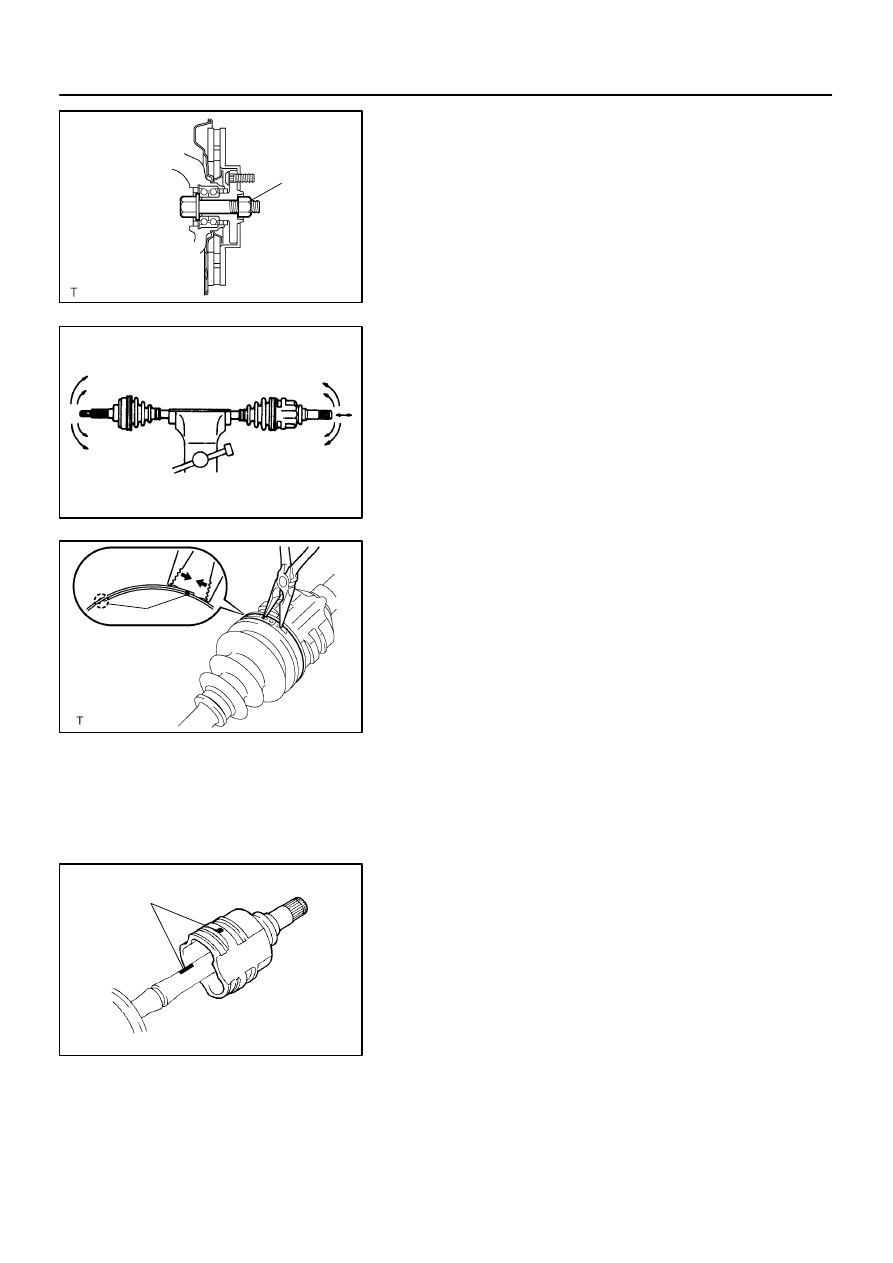
14.
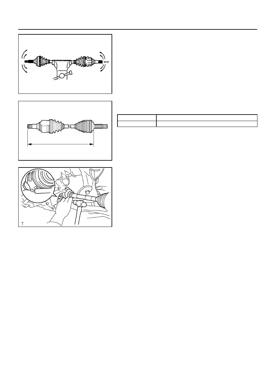
INSPECT FRONT DRIVE SHAFT ASSY LH
(a)
Check that there is no remarkable play in the outboard
joint.
(b)
Check that the inboard joint slides smoothly in the thrust
direction.
(c)
Check that there is no remarkable play in the radial direc-
tion of the inboard joint.
(d)
Check the boots for damage.
NOTICE:
Keep the drive shaft assy level during inspection.
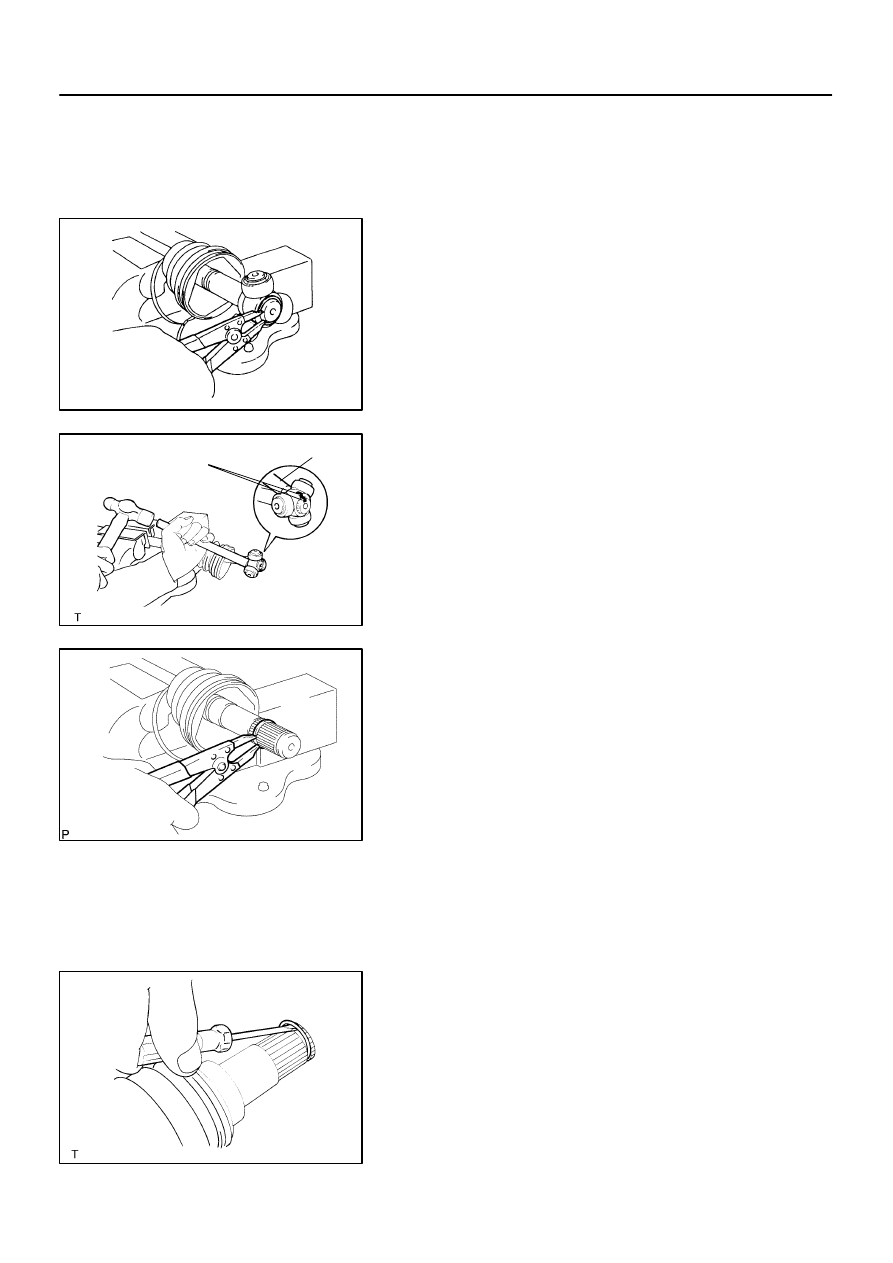
15.
REMOVE FRONT AXLE INBOARD JOINT BOOT LH
NO.2 CLAMP
(a)
Using a needle nose pliers, remove the inboard joint boot
LH No.2 clamp as shown in the illustration.
16.
REMOVE FRONT AXLE INBOARD JOINT BOOT LH CLAMP
(a)
Using a side cutter, cut the inboard joint boot LH clamp, then remove it.
17.
SEPARATE INBOARD JOINT BOOT
(a)
Separate the inboard joint boot from the inboard joint sub–assy LH.
18.
REMOVE FRONT AXLE INBOARD JOINT SUB–ASSY
LH
(a)
Remove the old grease from the inboard joint sub–assy
LH.
(b)
Place matchmarks on the inboard joint sub–assy LH and
outboard joint shaft assy.
NOTICE:
Do not punch the marks.
F40223
F40224
Matchmarks
Brass Bar
D27484
C57543
–
DRIVE SHAFT / PROPELLER SHAFT
FRONT DRIVE SHAFT
30–9
1274
Author:
Date:
2004 COROLLA (RM1037U)
(c)
Remove the inboard joint sub–assy LH from the outboard
joint shaft assy.
(d)
Using a snap ring expander, remove the inner LH shaft
snap ring.
(e)
Place matchmarks on the outboard joint shaft assy and
tripod joint assy.
NOTICE:
Do not punch the marks.
(f)
Using a brass bar and a hammer, remove the tripod joint
assy from the outboard joint shaft assy.
NOTICE:
Do not tap the roller.
(g)
Using a snap ring expander, remove the inner LH shaft
snap ring.
(h)
Remove the inboard joint boot LH No.2 clamp, inboard
joint boot and inboard joint boot LH clamp.
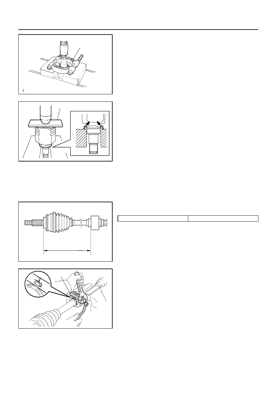
19.
REMOVE DRIVE SHAFT DAMPER (RH DRIVE SHAFT)
(a)
Using a side cutter, cut the drive shaft damper setting clamp, then remove it.
(b)
Remove the drive shaft damper.
20.
REMOVE FRONT DRIVE SHAFT LH HOLE SNAP RING
(a)
Using a screwdriver, remove the LH hole snap ring.
F40225
SST
F40226
SST
D27407
(A)
D27408
Hold
Turn
SST
30–10
–
DRIVE SHAFT / PROPELLER SHAFT
FRONT DRIVE SHAFT
1275
Author:
Date:
2004 COROLLA (RM1037U)
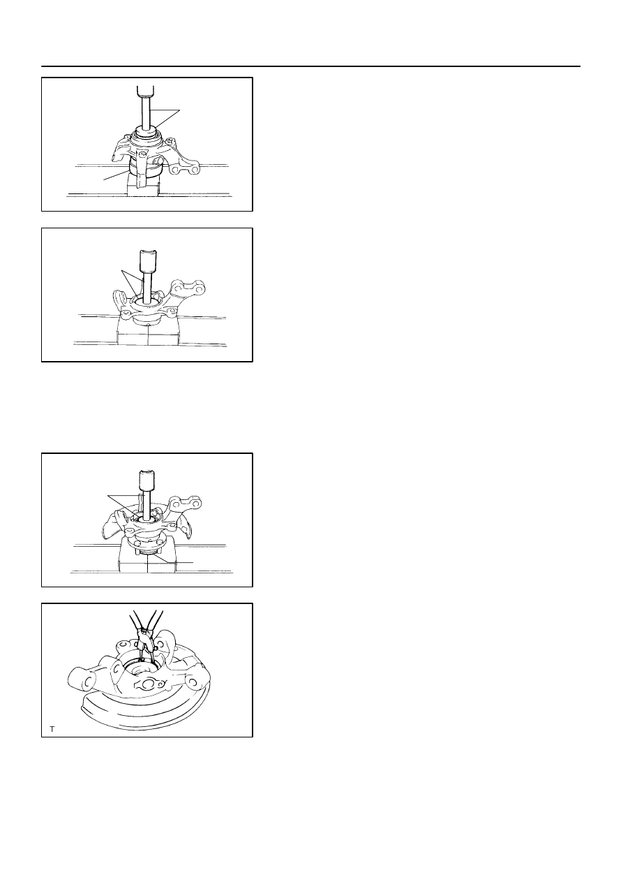
21.
REMOVE FRONT DRIVE SHAFT DUST COVER LH
(a)
Using SST and a press, remove the dust cover LH.
SST
09950–00020
22.
INSTALL FRONT DRIVE SHAFT DUST COVER LH
(a)
Using SST and a press, install a new dust cover LH, as
shown in the illustration.
SST
09527–10011
NOTICE:
Dust cover should be installed completely.
Be careful not to damage the dust cover.
23.
INSTALL FRONT DRIVE SHAFT LH HOLE SNAP RING
(a)
Install a new LH hole snap ring.
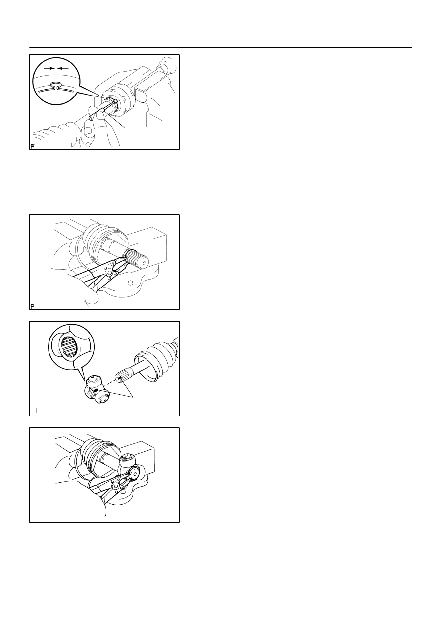
24.
INSTALL DRIVE SHAFT DAMPER (RH DRIVE SHAFT)
(a)
Set the distance, as described below.
Distance (A)
440 mm
2 mm (17.32
0.08 in.)
(b)
Through the damper setting clamp to the shaft.
(c)
Mount drive shaft in a soft vise.
(d)
Secure the damper setting clamp onto the damper.
(e)
Place SST onto the damper setting clamp.
SST
09521–24010
(f)
Tighten the SST so that the clamp is pinched.
NOTICE:
Do not overtighten the SST.
D27485
SST
D27484
F40227
Matchmarks
F40223
–
DRIVE SHAFT / PROPELLER SHAFT
FRONT DRIVE SHAFT
30–11
1276
Author:
Date:
2004 COROLLA (RM1037U)
(g)
Using SST, adjust the clearance of the damper setting
clamp.
SST
09240–00020 (09242–00150)
Clearance: 1.5 mm (0.059 in.) or less
25.
INSTALL FRONT AXLE INBOARD JOINT SUB–ASSY
LH
HINT:
Before installing the boot, wrap the spline of the drive shaft with
vinyl tape to prevent the boot from being damaged.
(a)
Install new parts to the outboard joint shaft assy in the fol-
lowing order.
(1)
Inboard joint boot LH clamp
(2)
Inboard joint boot
(3)
Inboard joint boot LH No.2 clamp
(b)
Using a snap ring expander, install a new inner LH shaft
snap ring.
(c)
Align the matchmarks, install tripod joint assy to the out-
board joint assy.
(d)
Using a brass bar and a hammer, install the tripod joint
assy.
NOTICE:
Do not tap the roller.
(e)
Using a snap ring expander, install a new inner LH shaft
snap ring.
(f)
Pack the inboard joint sub–assy LH with grease.
Grease Capacity: 135 – 155 g (4.8 – 5.5 oz.)
F40222
Matchmarks
D26925
SST
Hold
Turn
D26926
SST
D27501
Claws
30–12
–
DRIVE SHAFT / PROPELLER SHAFT
FRONT DRIVE SHAFT
1277
Author:
Date:
2004 COROLLA (RM1037U)
(g)
Align the matchmarks, install the inboard joint sub–assy
LH to the outboard joint shaft assy.
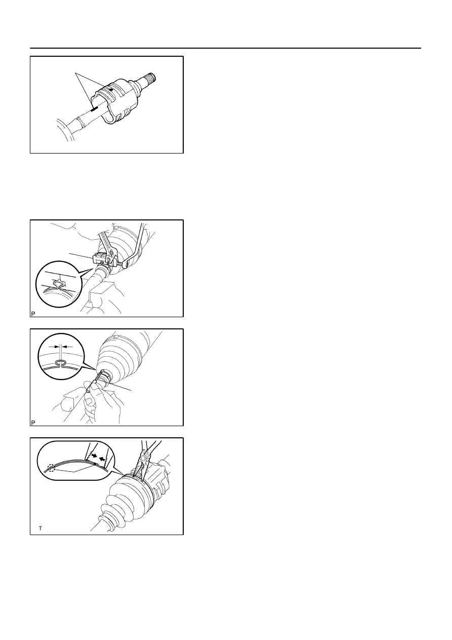
26.
INSTALL INBOARD JOINT BOOT
(a)
Install the inboard joint boot to the inboard joint assy and outboard joint shaft assy.
27.
INSTALL FRONT AXLE INBOARD JOINT BOOT LH
CLAMP
(a)
Mount drive shaft in a soft vise.
(b)
Secure the clamp onto the boot.
(c)
Place SST onto the clamp.
SST
09521–24010
(d)
Tighten the SST so that the clamp is pinched.
NOTICE:
Do not overtighten the SST.
(e)
Using SST, adjust the clearance of the clamp.
SST
09240–00020 (09242–00150)
Clearance: 1.5 mm (0.059 in.) or less.
28.
INSTALL FRONT AXLE INBOARD JOINT BOOT LH
NO.2 CLAMP
(a)
Using a needle nose pliers, install the inboard joint boot
LH No.2 clamp as shown in the illustration.
N00191
D27409
(A)
C81127
–
DRIVE SHAFT / PROPELLER SHAFT
FRONT DRIVE SHAFT
30–13
1278
Author:
Date:
2004 COROLLA (RM1037U)
29.
INSPECT FRONT DRIVE SHAFT ASSY LH
(a)
Check that there is no remarkable play in the outboard
joint.
(b)
Check that the inboard joint slides smoothly in the thrust
direction.
(c)
Check that there is no remarkable play in the radial direc-
tion of the inboard joint.
(d)
Check the boots for damage.
NOTICE:
Keep the drive shaft assy level during inspection.
HINT:
For dimension (A), refer to the following table.
RH
848.3
5.0 mm (33.398
0.197 in.)
LH
569.3
5.0 mm (22.413
0.197 in.)
30.
INSTALL FRONT DRIVE SHAFT ASSY LH
(a)
A/T:
Coat the spline of the inboard joint shaft assy with ATF.
(b)
M/T:
Coat the spline of the inboard joint shaft assy with gear oil.
(c)
Align the shaft splines, install the drive shaft assy with a
brass bar and a hammer.
NOTICE:
Set the hole snap ring with opening side facing down-
wards.
Be careful not to damage the oil seal.
HINT:
Whether the inboard joint shaft is in contact with the pinion shaft
or not can be known from the sound or feeling when driving it
in.
31.
INSTALL FRONT DRIVE SHAFT ASSY RH
HINT:
Install the RH side by the same procedure as the LH side.
NOTICE:
Do not damage the oil seal.
32.
INSTALL FRONT AXLE ASSY LH
(a)
Install the drive shaft assy LH to the front axle assy LH.
NOTICE:
Be careful not to damage the outboard joint boot.
w/ ABS:
Be careful not to damage the speed sensor rotor.
C80293
C80291
C80292
F13686
Turn
Hold
30–14
–
DRIVE SHAFT / PROPELLER SHAFT
FRONT DRIVE SHAFT
1279
Author:
Date:
2004 COROLLA (RM1037U)
33.
INSTALL FRONT SUSPENSION ARM SUB–ASSY
LOWER NO.1 LH
(a)
Install the lower ball joint to the front suspension arm sub–
assy lower No.1 LH with a bolt and 2 nuts.
Torque: 89 N
⋅
m (908 kgf
⋅
cm, 66 ft
⋅
lbf)
34.
INSTALL TIE ROD END SUB–ASSY LH
(a)
Install the tie rod end sub–assy LH to the steering knuckle with the nut.
Torque: 49 N
⋅
m (500 kgf
⋅
cm, 36 ft
⋅
lbf)
(b)
Install a new cotter pin.
NOTICE:
If the holes for the cotter pin are not aligned, tighten the nut further to 60
.
35.
INSTALL SPEED SENSOR FRONT LH (W/ ABS)
(a)
Install the speed sensor front LH and flexible hose to
shock absorber assy front LH with the bolt.
Torque: 29 N
⋅
m (296 kgf
⋅
cm, 21 ft
⋅
lbf)
(b)
Install the speed sensor front LH to the steering knuckle
with the bolt.
Torque: 8.0 N
⋅
m (82 kgf
⋅
cm, 71 ft
⋅
lbf)
NOTICE:
Be careful not to damage the speed sensor.
Keep the speed sensor clean.
Do not twist the sensor wire when installing the sen-
sor.
36.
INSTALL FRONT STABILIZER LINK ASSY LH
(a)
Install the front stabilizer link assy LH with the nut.
Torque: 74 N
⋅
m (755 kgf
⋅
cm, 55 ft
⋅
lbf)
HINT:
If the ball joint turns together with the nut, use a hexagon
wrench (6 mm) to hold the stud.
C68609
–
DRIVE SHAFT / PROPELLER SHAFT
FRONT DRIVE SHAFT
30–15
1280
Author:
Date:
2004 COROLLA (RM1037U)
37.
INSTALL FRONT AXLE HUB LH NUT
(a)
Install a new hub LH nut.
Torque: 216 N
⋅
m (2,200 kgf
⋅
cm, 159 ft
⋅
lbf)
(b)
Using a chisel and a hammer, stake the hub LH nut.
38.
INSTALL FRONT WHEEL
Torque: 103 N
⋅
m (1,050 kgf
⋅
cm, 76 ft
⋅
lbf)
39.
ADD MANUAL TRANSAXLE OIL (M/T TRANSAXLE)
40.
INSPECT AND ADJUST MANUAL TRANSAXLE OIL (M/T TRANSAXLE) (See page
41–2
)
41.
ADD AUTOMATIC TRANSAXLE FLUID (A/T TRANSAXLE)
42.
INSPECT AND ADJUST AUTOMATIC TRANSAXLE FLUID (A/T TRANSAXLE) (See page
40–2
)
43.
INSPECT AND ADJUST FRONT WHEEL ALIGNMENT (See page
26–5
)
44.
CHECK ABS SPEED SENSOR SIGNAL (W/ ABS) (See page
05–297
)
300A3–02
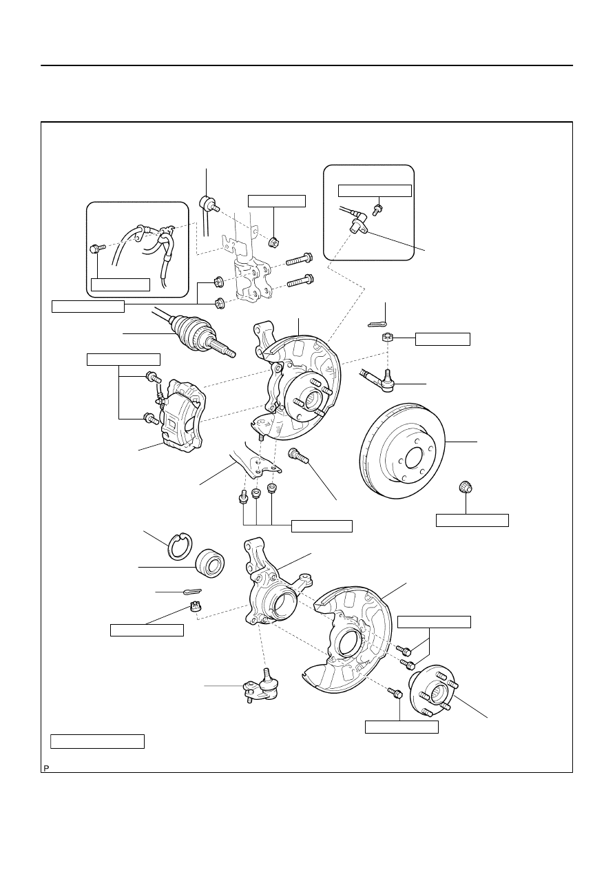
D27489
Cotter Pin
w/ ABS:
Front Axle Assy LH
Lower Ball Joint
Assy Front LH
w/ ABS:
Speed Sensor Front LH
Front Drive Shaft
Assy LH
8.0 (82, 71 in.
⋅
lbf)
29 (296, 21)
Front Stabilizer Link Assy LH
74 (755, 55)
153 (1,560, 113)
Tie Rod End Sub–assy LH
Front Disc
49 (500, 36)
Front Axle Hub LH Nut
216 (2,200, 159)
106.8 (1,089, 79)
Front Axle LH Hub Bolt
N
⋅
m (kgf
⋅
cm, ft
⋅
lbf)
: Spedified torque
Non–reusable parts
8.3 (85, 73 in.
⋅
lbf)
8.3 (85, 73 in.
⋅
lbf)
89 (908, 66)
Steering Knuckle LH
Disc Brake Dust Cover Front LH
Front Axle
Hub Sub–assy LH
Front Axle Hub
LH Bearing
Cotter Pin
103 (1,050, 76)
Front Axle Hub LH
Hole Snap Ring
Front Suspension Arm
Sub–assy Lower No. 1 LH
Front Disc Brake
Caliper Assy LH
30–16
–
DRIVE SHAFT / PROPELLER SHAFT
FRONT AXLE HUB SUB–ASSY LH
1281
Author:
Date:
2004 COROLLA (RM1037U)
FRONT AXLE HUB SUB–ASSY LH
COMPONENTS
300A4–04
C67088
D27403
C93871
–
DRIVE SHAFT / PROPELLER SHAFT
FRONT AXLE HUB SUB–ASSY LH
30–17
1282
Author:
Date:
2004 COROLLA (RM1037U)
REPLACEMENT
HINT:
COMPONENTS: See page
30–16
1.
REMOVE FRONT WHEEL
2.
REMOVE FRONT AXLE HUB LH NUT (See page
30–6
)
SST
09930–00010
3.
SEPARATE FRONT STABILIZER LINK ASSY LH (See page
30–6
)
4.
SEPARATE SPEED SENSOR FRONT LH (W/ ABS) (See page
30–6
)
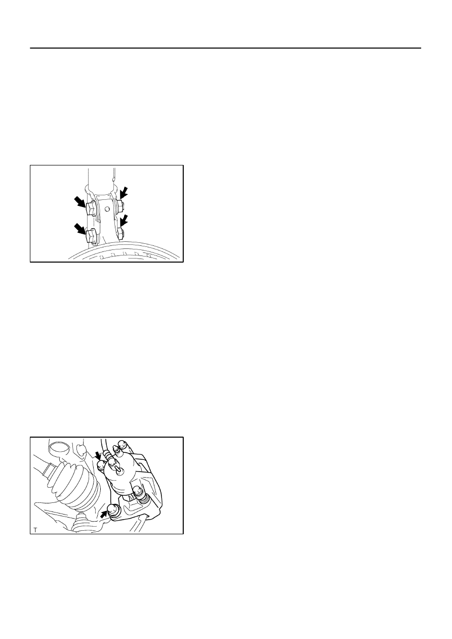
5.
SEPARATE FRONT DISC BRAKE CALIPER ASSY LH
(a)
Remove the 2 bolts, separate the brake caliper assy LH
from the steering knuckle.
6.
REMOVE FRONT DISC
7.
SEPARATE TIE ROD END SUB–ASSY LH (See page
30–6
)
SST
09628–62011
8.
SEPARATE FRONT SUSPENSION ARM SUB–ASSY LOWER NO.1 LH (See page
30–6
)
9.
REMOVE FRONT AXLE ASSY LH
(a)
Using a plastic hammer, separate the front drive shaft
assy LH from the axle hub.
NOTICE:
Be careful not to damage the boot.
w/ ABS:
Be careful not to damage the speed sensor rotor.
(b)
Remove the 2 bolts, nuts and front axle assy LH.
F40228
SST
F40229
D27402
SST
D27406
SST
SST
Hold
Turn
30–18
–
DRIVE SHAFT / PROPELLER SHAFT
FRONT AXLE HUB SUB–ASSY LH
1283
Author:
Date:
2004 COROLLA (RM1037U)
10.
REMOVE LOWER BALL JOINT ASSY FRONT LH
(a)
Remove the cotter pin and nut.
(b)
Using SST, remove the lower ball joint assy front LH.
SST
09628–62011
11.
REMOVE FRONT AXLE HUB LH HOLE SNAP RING
(a)
Using a snap ring pliers, remove the LH hole snap ring.
12.
REMOVE FRONT AXLE HUB SUB–ASSY LH
(a)
Using SST, remove the hub sub–assy LH.
SST
09520–00031
(b)
Using SST, remove the inner race of hub LH bearing from
the hub sub–assy LH.
SST
09950–40011 (09951–04020, 09952–04010,
09953–04030, 09954–04010, 09955–04061,
09957–04010, 09958–04011), 09950–60010
(09951–00370)
13.
REMOVE DISC BRAKE DUST COVER FRONT LH
(a)
Remove the 3 bolts and dust cover front LH.
F40230
SST
SST
F40231
SST
F40232
SST
SST
F40229
–
DRIVE SHAFT / PROPELLER SHAFT
FRONT AXLE HUB SUB–ASSY LH
30–19
1284
Author:
Date:
2004 COROLLA (RM1037U)
14.
REMOVE FRONT AXLE HUB LH BEARING
(a)
Place the inner race of hub LH bearing on the outer race
of hub LH bearing.
(b)
Using SST and a press, remove the hub LH bearing from
the steering knuckle.
SST
09527–17011, 09950–60010 (09951–00640),
09950–70010 (09951–07100)
15.
INSTALL FRONT AXLE HUB LH BEARING
(a)
Using SST and a press, install a new hub LH bearing to
the steering knuckle.
SST
09950–60020 (09951–00720), 09950–70010
(09951–07100)
16.
INSTALL DISC BRAKE DUST COVER FRONT LH
(a)
Install the dust cover front LH with the 3 bolts.
Torque: 8.3 N
⋅
m (85 kgf
⋅
cm, 73 in.
⋅
lbf)
17.
INSTALL FRONT AXLE HUB SUB–ASSY LH
(a)
Using SST and a press, install the hub sub–assy LH.
SST
09608–32010, 09950–60010 (09951–00600),
09950–70010 (09951–07100)
18.
INSTALL FRONT AXLE HUB LH HOLE SNAP RING
(a)
Using snap ring pliers, install a new LH hole snap ring.
C93871
C67088
30–20
–
DRIVE SHAFT / PROPELLER SHAFT
FRONT AXLE HUB SUB–ASSY LH
1285
Author:
Date:
2004 COROLLA (RM1037U)
19.
INSTALL LOWER BALL JOINT ASSY FRONT LH
(a)
Install the lower ball joint assy front LH, torque the nut.
Torque: 103 N
⋅
m (1,050 kgf
⋅
cm, 76 ft
⋅
lbf)
(b)
Install a new cotter pin.
NOTICE:
If the holes for the cotter pin are not aligned, tighten the nut further up to 60
.
20.
INSTALL FRONT AXLE ASSY LH
(a)
Install the 2 bolts, nuts and front axle assy LH to the shock
absorber.
Torque: 153 N
⋅
m (1,560 kgf
⋅
cm, 113 ft
⋅
lbf)
NOTICE:
Only when reusing the bolts and nuts, apply engine oil to
the screw part of the nuts.
(b)
Push the front axle assy toward the outside of the vehicle,
fit the splined part of the drive shaft assy to that of the front
axle assy, insert the drive shaft assy into the front axle
assy.
NOTICE:
Do not push out the front axle assy excessively.
Be careful not to damage the drive shaft outboard
joint boot.
w/ ABS:
Be careful not to damage the speed sensor rotor.
21.
INSTALL FRONT SUSPENSION ARM SUB–ASSY LOWER NO.1 LH (See page
30–6
)
22.
INSTALL TIE ROD END SUB–ASSY LH (See page
30–6
)
23.
INSTALL FRONT STABILIZER LINK ASSY LH (See page
30–6
)
24.
INSTALL FRONT DISC
25.
INSTALL FRONT DISC BRAKE CALIPER ASSY LH
(a)
Install the brake caliper assy LH with the 2 bolts to the
steering knuckle.
Torque: 106.8 N
⋅
m (1,089 kgf
⋅
cm, 79 ft
⋅
lbf)
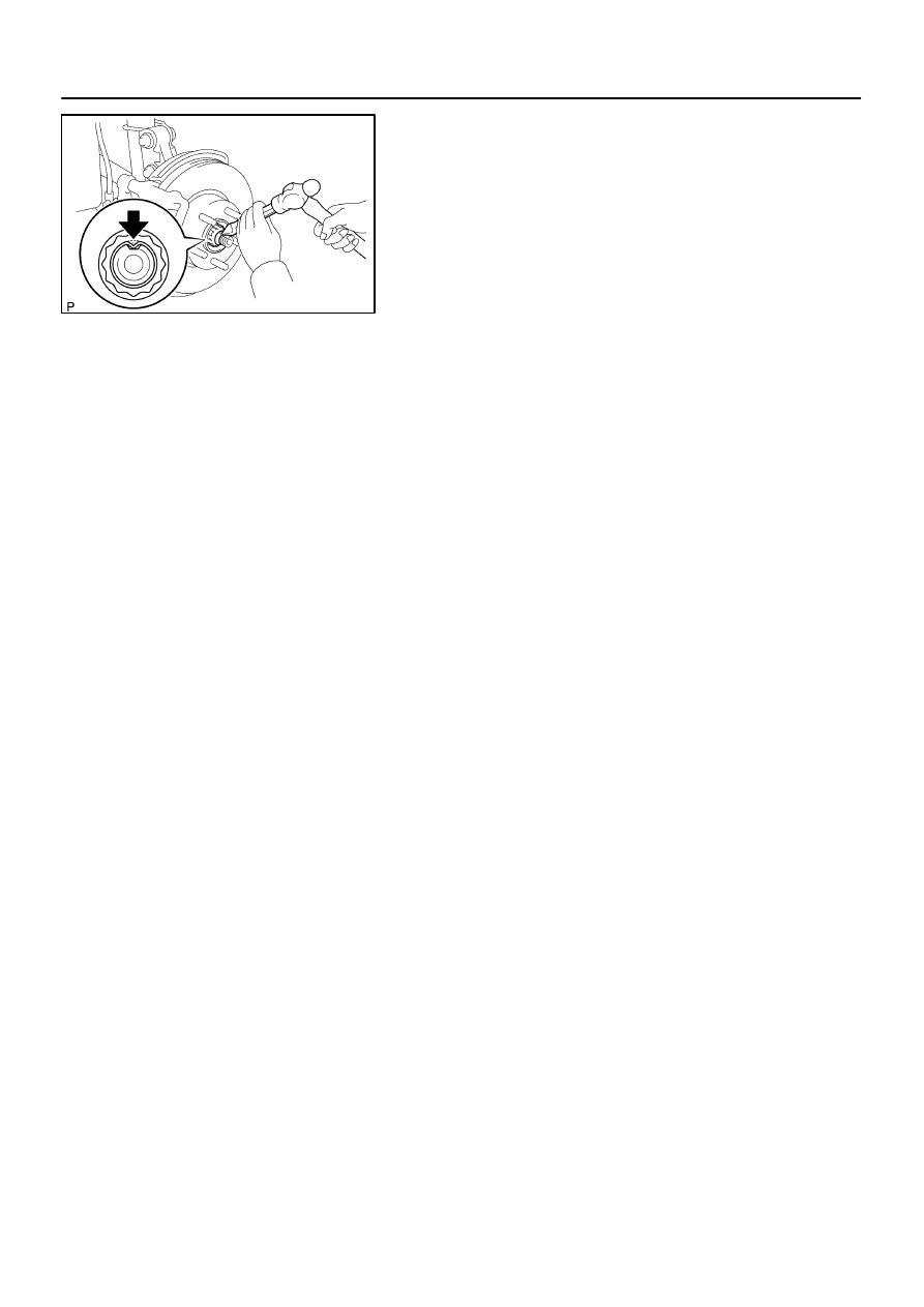
26.
INSTALL FRONT AXLE HUB LH NUT
(a)
Using a socket wrench (30 mm), install a new hub LH nut.
Torque: 216 N
⋅
m (2,203 kgf
⋅
cm, 159 ft
⋅
lbf)
27.
SEPARATE FRONT DISC BRAKE CALIPER ASSY LH
28.
REMOVE FRONT DISC
D26919
D26920
C68609
–
DRIVE SHAFT / PROPELLER SHAFT
FRONT AXLE HUB SUB–ASSY LH
30–21
1286
Author:
Date:
2004 COROLLA (RM1037U)
29.
INSPECT BEARING BACKLASH
(a)
Using a dial indicator, check the backlash near the center
of the axle hub.
Maximum: 0.05 mm (0.0020 in.)
If the backlash exceeds the maximum, replace the front axle
hub bearing.
30.
INSPECT AXLE HUB DEVIATION
(a)
Using a dial indicator, check the deviation at the surface
of the axle hub outside the hub bolt.
Maximum: 0.05 mm (0.0020 in.)
If the backlash exceeds the maximum, replace the front axle
hub sub–assy.
31.
INSTALL FRONT DISC
32.
INSTALL FRONT DISC BRAKE CALIPER ASSY LH
33.
INSTALL SPEED SENSOR FRONT LH (W/ ABS) (See page
30–6
)
34.
INSTALL FRONT AXLE HUB LH NUT
(a)
Using a chisel and a hammer, stake the hub LH nut.
35.
INSTALL FRONT WHEEL
Torque: 103 N
⋅
m (1,050 kgf
⋅
cm, 76 ft
⋅
lbf)
36.
INSPECT AND ADJUST FRONT WHEEL ALIGNMENT (See page
26–5
)
37.
CHECK ABS SPEED SENSOR SIGNAL (W/ ABS) (See page
05–297
)
300A5–02
D27405
SST
Turn
Hold
D27401
Washer
Nut
Turn
Hold
30–22
–
DRIVE SHAFT / PROPELLER SHAFT
FRONT AXLE LH HUB BOLT
1287
Author:
Date:
2004 COROLLA (RM1037U)
FRONT AXLE LH HUB BOLT
REPLACEMENT
HINT:
COMPONENTS: See page
30–16
1.
REMOVE FRONT WHEEL
2.
SEPARATE FRONT DISC BRAKE CALIPER ASSY LH (See page
30–17
)
3.
REMOVE FRONT DISC
4.
REMOVE FRONT AXLE LH HUB BOLT
(a)
Using SST and a hammer handle or an equivalent, re-
move the LH hub bolt.
SST
09628–10011
5.
INSTALL FRONT AXLE LH HUB BOLT
(a)
Install a washer and nut to a new LH hub bolt as shown
in the illustllation.
(b)
Using a hammer handle or an equivalent to hold the hub
sub–assy LH, install the LH hub bolt by tightening the nut.
6.
INSTALL FRONT DISC
7.
INSTALL FRONT DISC BRAKE CALIPER ASSY LH (See page
30–17
)
8.
INSTALL FRONT WHEEL
Torque: 103 N
⋅
m (1,050 kgf
⋅
cm, 76 ft
⋅
lbf)
300A6–02
D26927
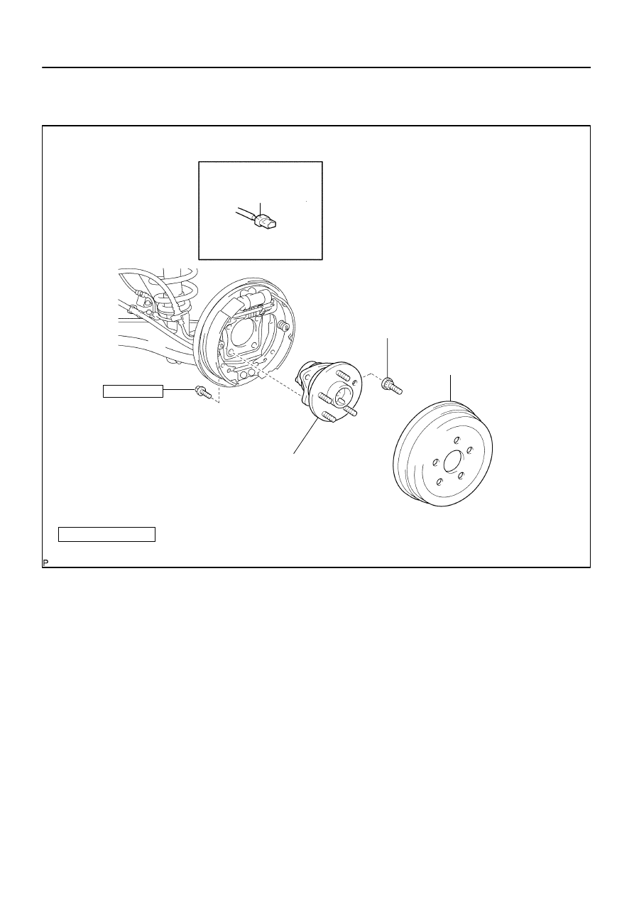
Rear Axle Hub & Bearing Assy LH
Rear Axle LH Hub Bolt
61 (622, 45)
N
⋅
m (kgf
⋅
cm, ft
⋅
lbf) : Spedified torque
Skid Control
Sensor Wire
Rear Brake Drum Sub–assy
x4
w/ ABS:
Non–reusable parts
–
DRIVE SHAFT / PROPELLER SHAFT
REAR AXLE HUB & BEARING ASSY LH
30–23
1288
Author:
Date:
2004 COROLLA (RM1037U)
REAR AXLE HUB & BEARING ASSY LH
COMPONENTS
300A7–03
C66800
C66800
D26921
30–24
–
DRIVE SHAFT / PROPELLER SHAFT
REAR AXLE HUB & BEARING ASSY LH
1289
Author:
Date:
2004 COROLLA (RM1037U)
REPLACEMENT
HINT:
COMPONENTS: See page
30–23
1.
REMOVE REAR WHEEL
2.
REMOVE REAR BRAKE DRUM SUB–ASSY
3.
DISCONNECT SKID CONTROL SENSOR WIRE (W/ ABS)
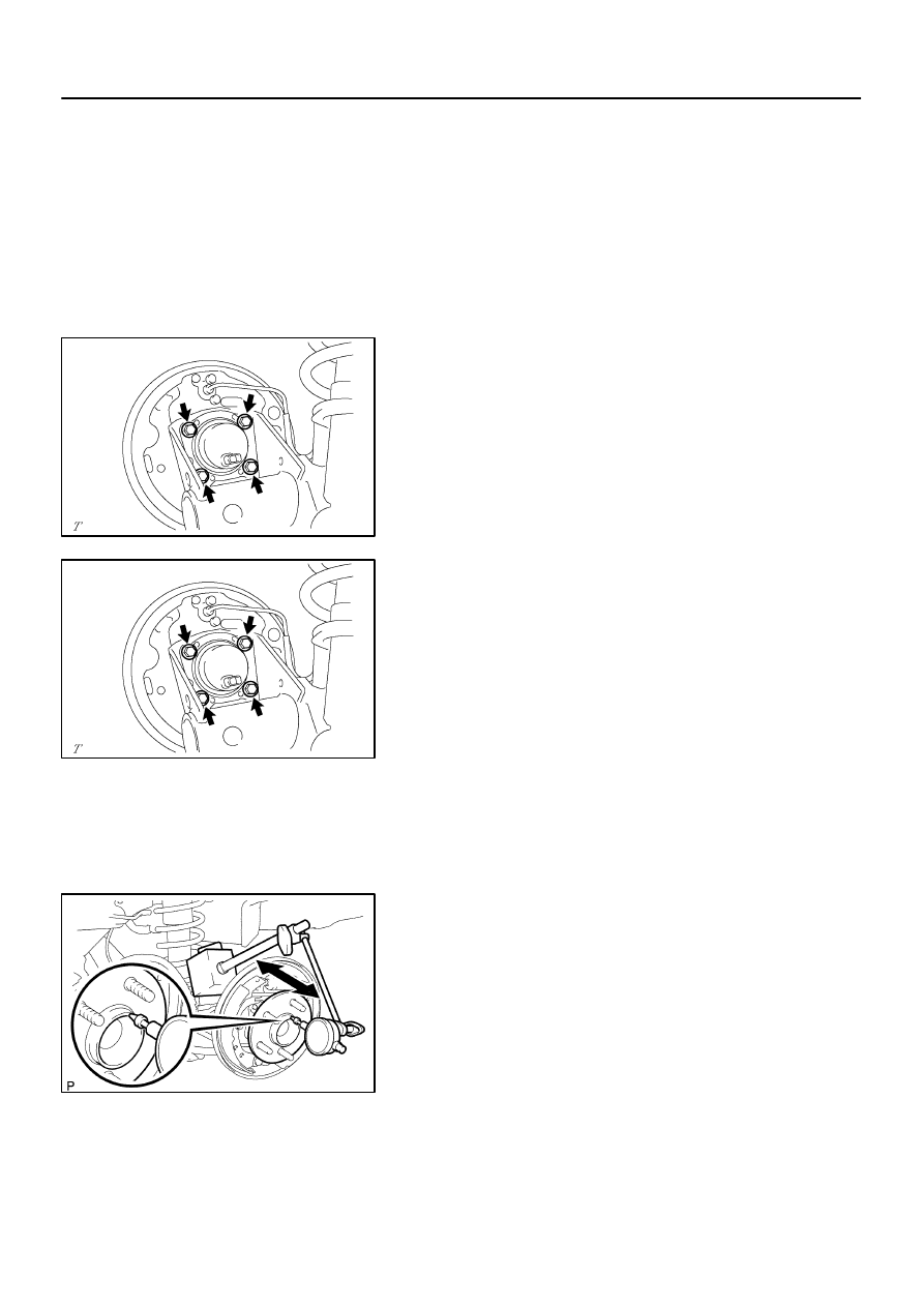
4.
REMOVE REAR AXLE HUB & BEARING ASSY LH
(a)
Remove the 4 bolts and hub & bearing assy LH.
5.
INSTALL REAR AXLE HUB & BEARING ASSY LH
(a)
Install the hub & bearing assy LH with the 4 bolts.
Torque: 61 N
⋅
m (622 kgf
⋅
cm, 45 ft
⋅
lbf)
6.
CONNECT SKID CONTROL SENSOR WIRE (W/ ABS)
7.
INSPECT BEARING BACKLASH
(a)
Set a dial indicator near the center of the axle hub and
check the backlash in the bearing shaft sirection.
Maximum: 0.05 mm (0.0020 in.)
If the backlash exceeds the maximum, replace the rear axle hub
& bearing assy LH.
D26922
–
DRIVE SHAFT / PROPELLER SHAFT
REAR AXLE HUB & BEARING ASSY LH
30–25
1290
Author:
Date:
2004 COROLLA (RM1037U)
8.
INSPECT AXLE HUB DEVIATION
(a)
Using a dial indicator, check the deviation at the surface
of the axle hub outside the hub bolt.
Maximum: 0.07 mm (0.0028 in.)
If the backlash exceeds the maximum, replace the rear axle hub
& bearing assy LH.
9.
INSTALL REAR BRAKE DRUM SUB–ASSY
10.
INSTALL REAR WHEEL
Torque: 103 N
⋅
m (1,050 kgf
⋅
cm, 76 ft
⋅
lbf)
11.
CHECK ABS SPEED SENSOR SIGNAL (W/ ABS) (See page
05–297
)
300A8–02
D26928
SST
Turn
Hold
D26929
Washer
Nut
Turn
Hold
30–26
–
DRIVE SHAFT / PROPELLER SHAFT
REAR AXLE LH HUB BOLT
1291
Author:
Date:
2004 COROLLA (RM1037U)
REAR AXLE LH HUB BOLT
REPLACEMENT
HINT:
COMPONENTS: See page
30–23
1.
REMOVE REAR WHEEL
2.
REMOVE REAR BRAKE DRUM SUB–ASSY
3.
REMOVE REAR AXLE LH HUB BOLT
(a)
Using SST and a hammer handle or an equivalent, re-
move the LH hub bolt.
SST
09628–10011
4.
INSTALL REAR AXLE LH HUB BOLT
(a)
Install a washer and nut to a new LH hub bolt as shown
in the illustration.
(b)
Using a hammer handle or an equivalent to hold the rear
axle hub & bearing assy LH, install the LH hub bolt by
tightening the nut.
5.
INSTALL REAR BRAKE DRUM SUB–ASSY
6.
INSTALL REAR WHEEL
Torque: 103 N
⋅
m (1,050 kgf
⋅
cm, 76 ft
⋅
lbf)
Wyszukiwarka
Podobne podstrony:
30 Drive Shafts
30 Drive and Propeller Shaft
4 Drive Shafts
30 Drive and Propeller Shaft
30 Struktury zaleznosci miedzy wskaznikami zrow rozw K Chmura
30 Wydatki rodziny
30 Tydzień zwykły, 30 środa
Fizyka 0 wyklad organizacyjny Informatyka Wrzesien 30 2012
geolog ogolna 30
Ustawa z 30 10 2002 r o ubezp społ z tyt wyp przy pracy i chor zawod
30 Obciążenia obiektów budowlanych, mostów drogowych i kolejowych
wyklad 29 i 30 tech bad
wyklad z kardiologii 30 11 2011
i 30 0 Przywodztwo w organizacji
F II wyklad 11 30 04 12
więcej podobnych podstron