
29
Drying of Pharmaceutical Products
Zdzisław Pakowski and Arun S. Mujumdar
CONTENTS
29.1 INTRODUCTION
The pharmaceutical industry is one in which quality
of the final product cannot be compromised. Any
deterioration of the product (e.g., by microbial infec-
tion, oxidation, thermal decomposition, contamin-
ation by metallic particles or by unremoved organic
solvent) must be avoided at any cost. In light of that
the Good Manufacturing Practices (GMP) for drug
manufacture (see, e.g., Ref. [1]) put numerous de-
mands on the drying stage of the drug manufactur-
ing process. Noncontaminating dryer construction
materials are used, like polished stainless steel or
enameled iron. Closed-cycle dryers are often re-
quired as moisture removed is often an organic
solvent or their mixture. Drying must be often
ß
2006 by Taylor & Francis Group, LLC.

performed in inert gas to avoid oxidation or explo-
sion if solvent is flammable. To avoid thermal de-
composition in many instances vacuum and freeze
drying must be employed.
All these requirements put dryers for pharmaceut-
icals among the most expensive and sophisticated
drying equipment. At the same time the wide variety
of drugs produced by any pharmaceutical company
(tens of thousands of individual drugs are produced
worldwide) in many different forms causes dryers in
the pharmaceutical industry to encompass a wide
range of types, both batch and continuous.
The manufacture of a drug that will be distributed
in nonliquid form (tablets, capsules, dragees) is
carried out in three subsequent stages:
1. Synthesis of intermediate products
2. Final synthesis of the drug
3. Manufacture of dosage forms
After each stage the products are dried. Selection
of a proper dryer for these products depends on the
properties of materials such as their form, thermal
sensitivity, tonnage, drying kinetics, and so on. Since
most pharmaceuticals are low-tonnage and high-
value products, considerations of energy saving are
usually of secondary importance in the selection of
the drying process.
29.2 CLASSIFICATION OF
PHARMACEUTICAL PRODUCTS WITH
RESPECT TO DRYER SELECTION
From the point of view of drying technology, all
substances dried in the pharmaceutical industry can
be classified into three major groups:
1. Granular materials: Solids in the form of indi-
vidual particles of the size approximately in the
range 0.05 to 5 mm
2. Pastelike materials: Solids mixed with liquid to
form a free-flowing paste; size of particles ap-
proximately in the range 0.1 to 50 mm
3. Solutions and suspensions: Solids dissolved or
suspended in liquid in the form of fine (10–50
m
m), ultrafine (0.1–10 mm), or colloidal (<0.1
m
m) suspensions
The criteria of classification are not clear-cut here,
and wet granular material of small particle size can as
well be classified as pastelike and a thin paste can be
classified as a suspension if it is pumpable. According
to the type of the material, appropriate drying systems
are chosen.
For the first group the following types of dryers
are generally used: convective (tray, band, fluid bed,
flash dryers, and their modifications) or contact
(vacuum dryers such as double-cone dryer-blender,
conical dryer with rotating helical mixer, paddle
dryer). Pastelike materials are dried in tray dryers,
band dryers equipped with extruding devices, and
spin-flash dryers. Finally, thin pastes can be dried in
spray dryers or on fluid beds or spouted beds of inert
particles. Small amounts of solutions and suspensions
are generally freeze-dried, especially if the product is
thermolabile.
Further selection of dryers is based on the drying
kinetics, which is closely associated with the structure
as represented by their mean pore size and the type of
the moisture–material bond. Sazhin has developed a
classification based in principle on Rebinder’s pro-
posal, which classifies all materials into four groups.
This classification [2], which can be used to help select
a dryer, is presented in Table 29.1. Although the
selection of the dryers is limited to dryers for granular
materials, this classification scheme has general valid-
ity. The quantitative basis of the classification is the
minimum pore diameter from which moisture is to be
removed during drying.
TABLE 29.1
Classification of Granular Materials
Group
Pore Size
(nm)
Drying Time in
Suspended State
Types of Dryers
Recommended
I
>
100
0.5–3.0 s
Cyclone dryers
Flash dryers
Two-stage
flash dryers
II
100–6
3–30 s
Two-stage
flash dryers
Fast spouted bed
III
6–4
0.5–2 min
Vortex dryers
Batch dryers
4–2
2–20 min
Fluid bed
Vibrated fluid bed
Batch dryers
IV
Ultramicropores,
particle
size 1–2 mm
10–60 min
Vibrated fluid bed
Multistage fluid bed
Batch dryers
40–90 min
Batch dryers
Suspended state
dryers not
recommended
Particle size
>
2 mm
>
90 min
ß
2006 by Taylor & Francis Group, LLC.

The four gro ups are categor ized as foll ows:
Group I: Nonp orous or capil lary-porou s solids
with large por e sizes. Only free mois ture is re-
moved dur ing drying. Sodium chlori de and acet-
ylosal icyclic acid (ASA) belong to this group .
Group II: Unifo rmly an d nonuni form ly porous
mate rials wi th pore sizes down to 6 nm . Mois-
ture remove d dur ing drying is phy sically or
physicoch emically bonde d. That is, it includes
free mois ture, mois ture of macro- an d micr o-
capil laries, and surfa ce-adso rbed mois ture.
Phenoba rbit al, methen amine (Urotropi n), and
sodium perborat e belong to this g roup.
Group III: Micropo rous or colloid -capilla ry-
poro us materials. Duri ng drying all phy -
sicochem ically adsorbed moisture is remove d.
The foll owing substa nces belong to this grou p:
6–4 nm subgroup , glucose and sulf adime thox-
ine; 4–2 nm sub group, calciu m gluconat e and
calci um glycer ophos phate.
Group IV: Ultram icropor ous material s. Pore size
is c omparabl e to the size of mo lecules of re-
moved moisture. Moist ure of ultr amicropo res
is remove d in intens e drying, whi ch corres ponds
to mois ture content s as low as 0.2–0. 1% or less .
Chem ically bonde d mois ture is also remove d in
this case.
Besides the pore size, which characterizes the drying
time of individual particles, granular materials have
certain flow properties that describe among other prop-
erties how easily they can be transferred into a sus-
pended state. Materials that have large cohesion tend
to form agglomerates and are difficult to dry in fluid
beds or pneumatic dryers. Agglomerates have larger
perimeters than individual particles, and the macro-
pores formed between particles increase the diffusional
heat and mass transfer resistance. Roughly, granular
materials are classified as free-flowing and sticky mater-
ials. The degree of stickiness depends on particle size
and viscosity of surface moisture. Generally the smaller
the particles and the more viscous the fluid the stickier
the product will be. Selection of a dryer for a free-
flowing material is usually simple whereas drying of a
sticky product may be a serious problem. Certain prod-
ucts not sticky at normal temperatures become sticky at
elevated temperatures due to plasticizing or dissolving
in moisture. This may lead to defluidization of a bed at a
certain temperature, for instance.
Granu lar mate rials are often class ified by size.
Accor ding to the Br itish Pha rmac opoeia class ification
shown in Table 29.2, they are divide d into six class es.
This c lassificat ion helps in dryer selection. Genera lly,
very fine powder s and ultrafin e powder s are not
recomm ended for drying in fluid bed dryers owing
to their very low entrain ment veloci ties an d often
poor fluidization quality due to agglomeration.
29.3 PROPERTIES OF PHARMACEUTICAL
PRODUCTS
29.3.1 P
HYSICAL
P
ROPERTIES
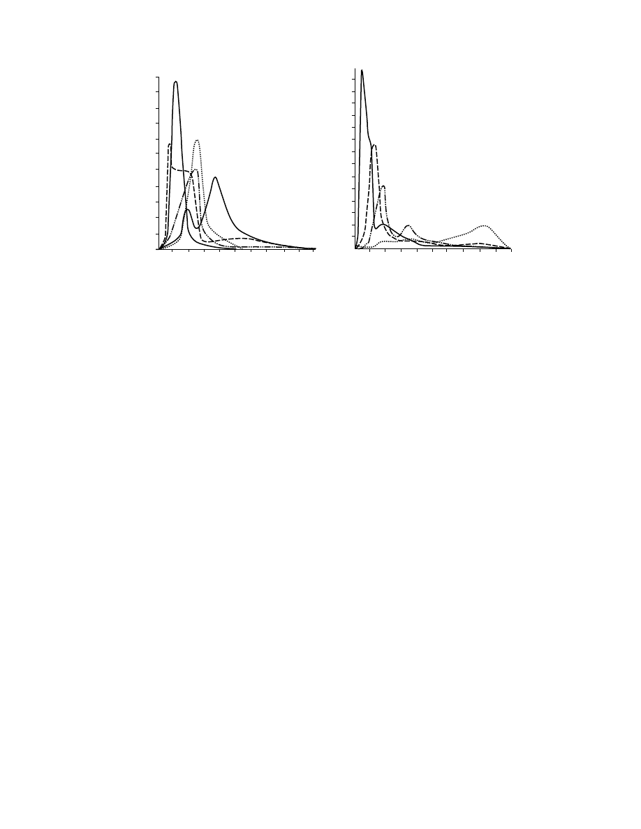
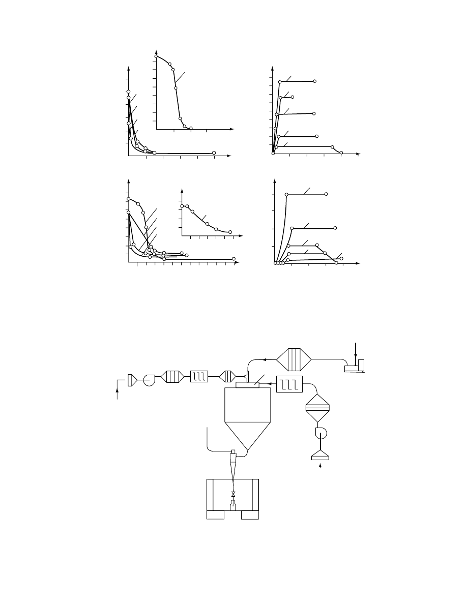
29.3.1.1 Particle Size
Pharmaceuticals are usually obtained by crystallization.
Under most conditions their particle size seldom grows
larger than 1 mm. Generally, owing to their low solu-
bility, the crystals are small or very small. The particle
size distribution of a typical pharmaceutical as meas-
ur ed by s ieve analy sis is shown in
. From the
point of view of drying technology, for monodisperse
materials, such as ASA and sodium p-aminosalicylate,
the aerodynamic conditions in dryers are much easier
to select. If particle size distribution is unimodal but
widespread (e.g., Urotropin or phenyl salicylate) or
bimodal (e.g., codeine, streptomycin, or sulfanilamide),
the material is more difficult to dry in suspended state
as particle segregation may occur.
Materials produced in spray dryers from solutions
and suspensions are characterized by a very small
particle size. Particle sizes in the range 1 to 500 mm
are observed. All powders must be granulated before
tableting. According to Remington [3], the following
granulate size should be used to produce tablets of
given diameter.
Tablet Diameter (in.)
Granulate Size (mesh)
0–3/16
20
7/32–5/16
16
11/32–13/32
14
>
7/16
12
TABLE 29.2
Classification of Granular Pharmaceuticals
According to Size (British Pharmacopoeia)
Class
Particle Size
Range (mm)
Coarse powder
100%
<
1680
40%
<
355
Moderately coarse
powder
100%
<
1680
40%
<
250
Moderately fine
powder
100%
<
355
40%
<
180
Fine powder
100%
<
180
Very fine powder
100%
<
125
Ultrafine powder
100%
<
50
90%
<
5
ß
2006 by Taylor & Francis Group, LLC.
About 10–20% of fine particles in granulate are
generally allowed as they improve the flow properties
of the granulate.
29.3.2 T
HERMAL
P
ROPERTIES
Among thermal properties, thermal decomposition
rate is of primary interest. Usually thermal decom-
position follows a first-order reaction kinetics, that is,
c
¼ c
0
e
kt
where c is the actual concentration, c
0
is the initial
concentration, k is the rate constant (1/s), and t is the
time (s).
The reaction rate constant depends on tempera-
ture according to Arrhenius theory:
k
¼ Ae
E=RT
where A is constant (1/s), E is the activation energy
(J/mol), R is the universal gas constant (J/(mol K)),
and T is temperature (K).
For example, thiamine hydrochloride in aqueous
solution has E
¼ 92.18 kJ/mol and A ¼ 9.5810
10
1/min. Processing such solution at 908C for 10 min
would result in c/c
0
¼ 0.949 (i.e., about 5% loss). One
has to remember that thermal decomposition is usu-
ally influenced by water content of the processed
material.
Other properties of interest include melting point
temperature, specific heat, and heat conductivity of
solid. They may be found in specialized books [2,4]
for most common pharmaceuticals.
29.3.3 S
ORPTIVE
P
ROPERTIES
Sorptive properties of the pharmaceutical products as
represented by their sorption isotherms reflect their
ability to absorb water from the air and are the source
of valuable information for the selection of dryers as
well as the packaging conditions. The sorption iso-
therm is the relationship between the relative humid-
ity of the air and the moisture content of solid in
equilibrium with this air.
They are usually measured by gravimetric methods,
where a known amount of solid of known initial
moisture content is exposed to a gas of specified
relative humidity. After sufficient time, the new
weight of the sample is measured, which allows one
to calculate the actual moisture content.
In most cases the sorption isotherm produced
under conditions of increasing humidity (sorption)
differs from that produced when humidity is de-
creased (desorption). This phenomenon, known as
sorption hysteresis, can sometimes be very substan-
tial. For drying purposes only desorption isotherms
are of practical significance.
Sorption isotherms should if possible be measured
under dynamic conditions, as in a condition of fluid-
ization. The use of sorption isotherms measured
under static conditions can lead to substantial errors
when used for calculations of fluid bed, pneumatic, or
11
Δ
n
/d
. mm
−
1
Δ
n
/d
. mm
−
1
4
3
5
2
1
10
9
8
7
6
5
4
3
2
1
0
14
10
11
12
13
9
8
7
6
5
4
3
2
1
0
1
4
2
3
0.2
(a)
(b)
0.4
0.6
0.8
1.0
d.mm
0.2
0.4
0.6
0.8
1.0
d.mm
FIGURE 29.1 Size distribution of typical pharmaceutical products: (a) 1, streptomycin sulfate; 2, ascorbic acid; 3, hydrate of
diaceto-2-keto-
L
-gulonic acid; 4, starch; 5, talcum; (b) 1, sulfanilamide; 2, acetylosalicyclic acid; 3, sodium p-aminosalicylate;
4, codeine
þ terpin hydrate. (From Golubev, L.G., Sazhin, B.S., and Valashek, E.R., Drying in Chemicopharmaceutical
Industry, Meditsina, Moscow, 1978 (in Russian). With permission.)
ß
2006 by Taylor & Francis Group, LLC.

other dryers with partic les suspen ded in the air. Sor p-
tion isot herms for a seri es of selected pharmac eu ticals
were tabula ted by Reprin tseva and Fedor ovich [4].
Analysis of their so rption isot herms allows one to
classif y the products an d give so me indica tions
about the selection of dryer.
M aterials with intens ive hyster esis for whi ch sorp-
tion and desorpt ion isotherms coincide only at two
points , at zero and saturati on hum idity, belong to
colloid al bodies acco rding to Rebi nder’s class ifi-
cation . Most of the final pharmac eutic al produ cts
belong to this group. All table ting formu lations co n-
taining star ch or gelatin are obt ained by spray dr ying
a mixt ure of the drug with all other table t compo n-
ents, such as lubri cants, binders , and diluent s, which
are co lloid in na ture.
M aterials that displ ay no sorption hysteresis , or if
their hyster esis is limit ed (the range RH 0.2–0. 9 or
over a narrow er range) , are classified as cap illary-
porous bodi es. As exa mples, ascorbi c acid, p-amin o-
benzosu lfamide, and he xameth ylenetetra mine may be
mentio ned here. Materials showing sorpti on iso-
therms intermed iate between these tw o ca tegories be-
long to the so -called capillary- colloid-po rous bodies,
and they include ASA and penici llin. The en ergy of
the solid –moisture bond increases from cap illary-
porous to colloidal bodies. Adeq uate drying temp-
erature s an d resid ence times must be used for dry ing
such difficult to dry solid s. The tempe rature of dry-
ing is direct ly proporti onal to the energy of the solid–
moisture bond. The drying tim e depends on parti cle
size and the amount of mo isture remove d.
M ore informat ion can be obtaine d from dry ing
kinetics and exp erimental measur ement s. These ex -
perime nts provide the ulti mate basis for selection of
the app ropria te dryer an d drying conditio n. Often
one may arrive at severa l alte rnate dry ing eq uipment
for drying a given pr oduct.
Som e infor matio n on moisture–m aterial bond
More specific infor mation on sorption isot herms for
most common mate rials used in the pharmac eutic al
indust ry together with measur ing methods may be
found in Stahl [5].
29.4 DRYER TYPES AND THEIR
PERFORMANCE
High-q uality standar ds and high price of the fina l
produc t demand high reliabil ity an d just ify more so-
phisticat ed con struction of pharmac eutic al dry ers
than dryers used in most other indust ries. Tradit ional
dryers of the pharmac eutical indu stry, such as shelf or
batch flui d be d dryers , are continuous ly sup pleme n-
ted by dryers first used in other fields of applic ation.
Increas ing quan tities of prod ucts may call for con -
tinuous dryers . Increased quality co ntrol an d large r
producti on rates continuous ly broaden the rang e of
dryer types us ed in the pha rmace utical indust ry. Thi s
chapter pr esents only the most wi dely used types of
dryers for pha rmace uticals. More infor mation on per-
forman ce of industrial dryers for pharmac eutic als is
given by Simon [6]. It shou ld be noted that most of
these dryers are discussed in greater detai l elsewhere
in this handbo ok.
29.4.1 D
IRECTLY
H
EATED
D
RYERS
: B
ATCH
D
RYERS
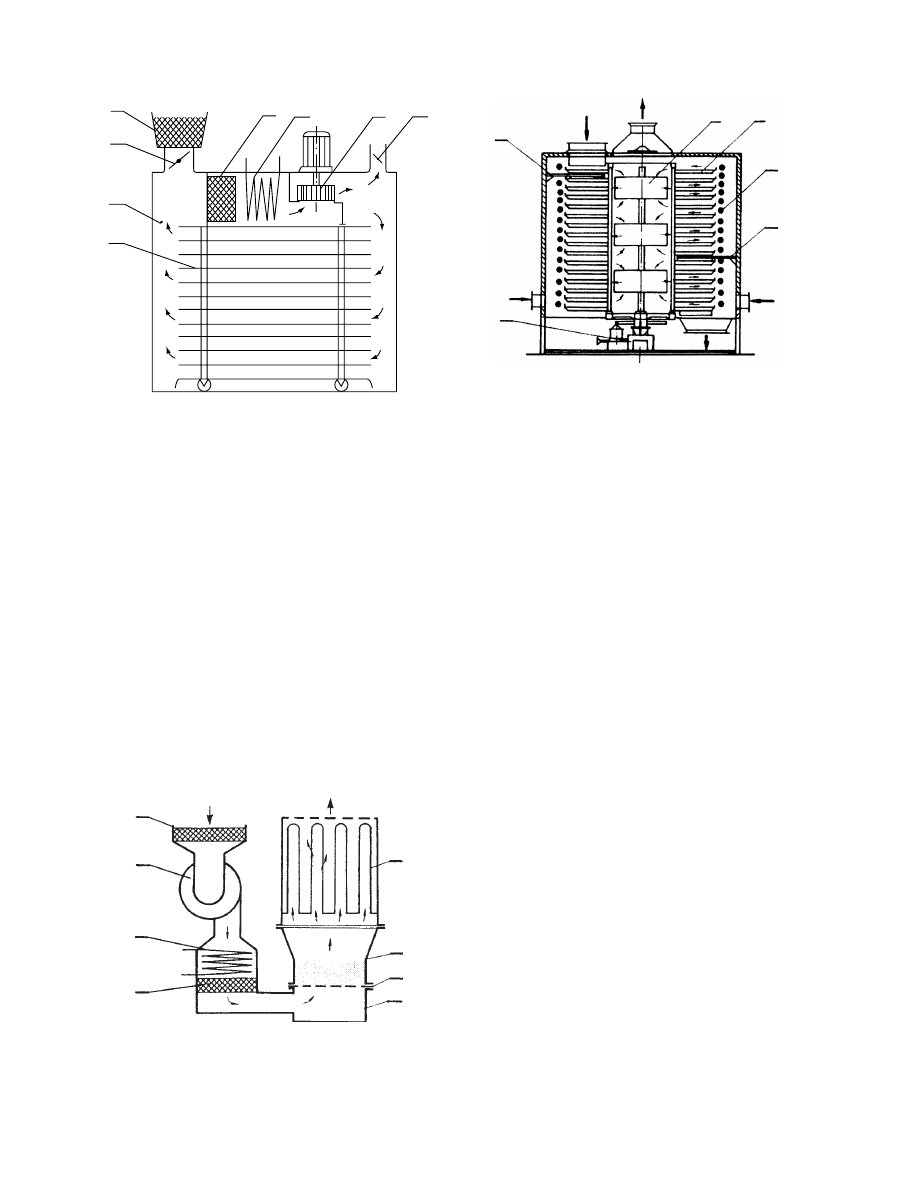
29.4.1 .1 Ovens
For smal l batches of pha rmace uticals, ovens are still a
good cho ice. They allow for placi ng mate rial upon
several shelve s, whi ch can be carried by a truck. Dur-
ing drying, hot air is cross- circulated be tween the
shelve s to permit drying of differen t pro ducts at the
same time. Inter nal circulati ng air filter s are often
provided (
) to protect against cross-contam-
ination of the products. Similar ovens can be used for
thermal sterilization of vials and bottles, for example.
29.4.1 .2 Flui d Bed Dryers
Small ba tch flui d bed dryers (
) a re ve ry
commonl y used in the pharmac eutical indust ry.
Owing to better a ir–solid co ntact, drying in fluid
beds is faster than in tray ovens and beca use of
good mixi ng product unifor mity is muc h improve d.
Usually they are sup plied with roll-on roll-off drying
chambers often eq uipped with an agitator. Air afte r
drying is filter ed, us ually in multicycl ones or bag
filters. The use of bag filter s is, howeve r, troublesome
if the dryer is often used for different produ cts as it
requir es very caref ul cleani ng.
29.4.2 D
IRECTLY
H
EATED
D
RYERS
: C
ONTINUOUS
D
RYERS
29.4.2.1 Band Dryers
Relatively seldom used in the manufacture of final
pharmaceutical products, band dryers find wide use
in drying of raw materials, especially herbal and me-
dicinal plants. Usually several bands in one-above-
another configuration are used. Bands are made of
stainless steel screens or perforated plates. Band
speeds from several centimeters to about 0.5 m/min
are used. Bandwidths vary from as low as 0.5 m up to
2 m. Drying air temperatures in the range 80–1008C,
initial moisture contents of 45–100%, (d.6) and drying
rates of 5–18 kg/m
2
h are usual in industrial practice.
ß
2006 by Taylor & Francis Group, LLC.

TABLE 29.3
Data on Water Sorption Properties of Selected Pharmaceutical Materials
Substance
Moisture Content (% Dry Basis)
Physicochemical Bond
Desorption
Sorption
Desorption
Maximum
Hygroscopic
Moisture
Content
Heat of
Sorption
(10
2
,
kJ/kmol)
Physicomechanical Bond
Polymolecular Adsorption
Monomolecular Adsorption
Capillary
Osmotic
Sorption
Penicillin
21.4
9.6
3.0
3.6
1.0
1.0
19.0
134.0
Streptomycin
20.0
10.0
9.0
12.0
6.8
6.0
25.0
158.0
Phenylsalicylate
—
—
—
—
0.18
—
1.0
58.12
Acetylosalicyclic acid
8.5
6.0
1.5
1.7
0.5
0.5
5.8
23.50
Sodium p-aminosalicylate
20.0
12.0
8.0
10.0
2.0
2.0
20.0
—
Ascorbic acid
13.0
13.0
0.5
0.6
0.25
0.25
2.0
8.95
Talcum
—
—
0.1
—
0.05
—
0.35
10.36
Starch
32.0
22.0
13.6
16.0
8.2
10.0
26.0
56.35
ß
2006
by
Taylor
&
Francis
Group,
LLC.
29.4.2 .2 Tur bo-Tray Dryers
Turbo -tray dryers , suitable for granula r feeds, ope r-
ate wi th rotat ing shelve s and forced convecti on of the
air ab ove the shelves (Figur e 29.4). The product layer
fed onto the first she lf is level ed by the set of stat ion-
ary blades, whi ch also scrat ch a series of grooves onto
the layer surfa ce. All blades are staggered so that a
new surfa ce layer is form ed by each set. This way the
layer is well mixed and dries unifor mly. After trave l-
ing one rotation, the material is wiped off by the last
blade and falls onto the lower shelf. The dryer can
have up to 30 trays or more a nd pro vide large resi -
dence times. Herm etic sealing of the whol e dryer is
easy so that solvent recover y can be achieve d.
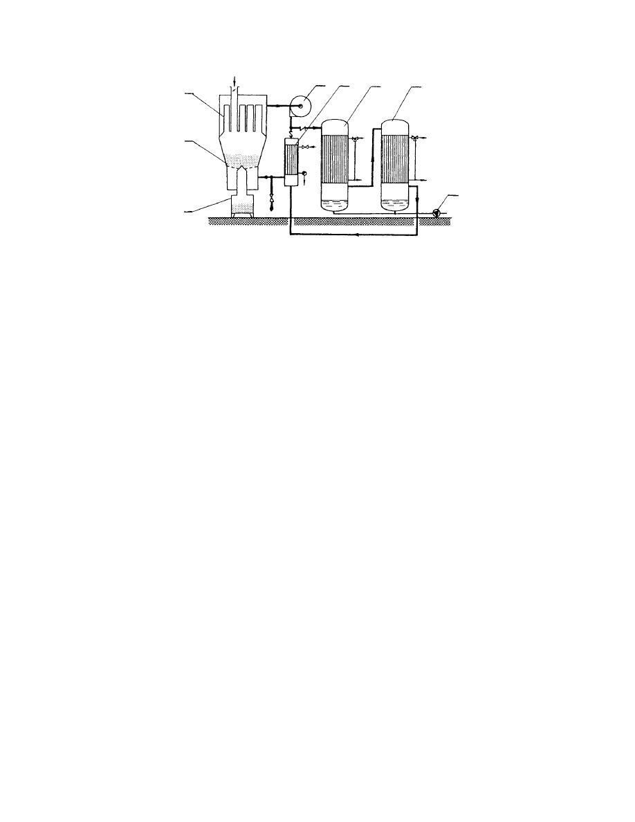
29.4.2 .3 Pne umat ic Dryers
In pneumat ic dryers the wet feed is introdu ced into a
stream of hot gas flowi ng with velocitie s of severa l
meters per second, usuall y in a verti cal insul ated duct.
Durin g their cocurrent co ntact mois ture is evap or-
ated, co nsumin g the sensible heat of the gas. High
evaporat ion rates (values as high as 240–1200 -kg
moisture per h and per m
2
of contact area are gener-
ally met) and co current co ntact protect the pa rticles
from overheat ing. Aft er a time of the order of a
fraction of a second to a few seconds, the dried ma-
terial an d gas leave the duc t and are sep arated in a
cyclone. Very short times of con tact allow drying only
the unboun d moisture from smal l particles .
To prolon g the contact time with the same dry er
height (or length ), spiral inserts may be install ed inside
the dryer tube. Simi lar to other direct ly heated dryers ,
they can operate in a closed cycle. A closed-cycl e
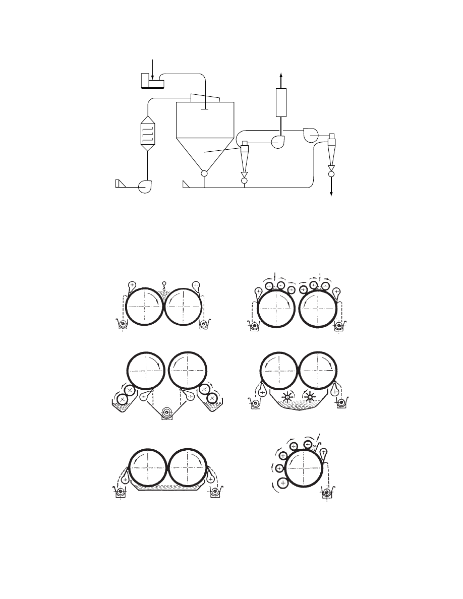
pneumatic dryer is shown schematically in
.
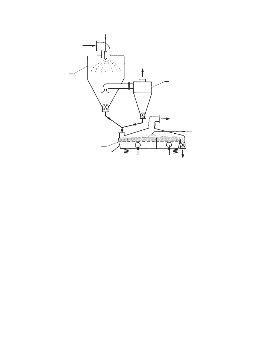
29.4.2 .4 Cyc lone Dryers
Observa tions of pne umatic dryers proved that a co n-
siderab le amount of total mois ture remove d evap or-
ates in the cyclone sep arator. Se veral new dryer types
were constr ucted that app ly the princi ple of vortex
flow. In ad dition, the cyclone dryers have particle
separation featu res. Centrifuga l force keeps large
and wet pa rticles rotating whereas small an d dry
particles can be carried away with gas. Adjus tment
of gas velocity can thus change the critical parti cle
size as well as resid ence time in the dryer.
29.4.2.4.1 Convex-Type Dryers
The constr uction of conve x-type dryers resem bles a
flat c yclone without the con ical bottom (
) .
1
6
3
5
3
4
6
2
FIGURE 29.2 Shelf batch dryer (1, shell; 2, truck with
shelves; 3, heater; 4, fan; 5, air filters; 6, valves).
1
7
6
4
5
6
2
3
FIGURE 29.3 Batch fluid bed dryer (1, fluidizing chamber;
2, gas distributor; 3, plenum chamber; 4, blower; 5, heater;
6, filters; 7, bag dust collector).
4 1
3
2
5
2
FIGURE 29.4 Turbo-tray dryer (1, shelves; 2, blades; 3,
heater; 4, fan rotors; 5, shelf and fan drive).
ß
2006 by Taylor & Francis Group, LLC.
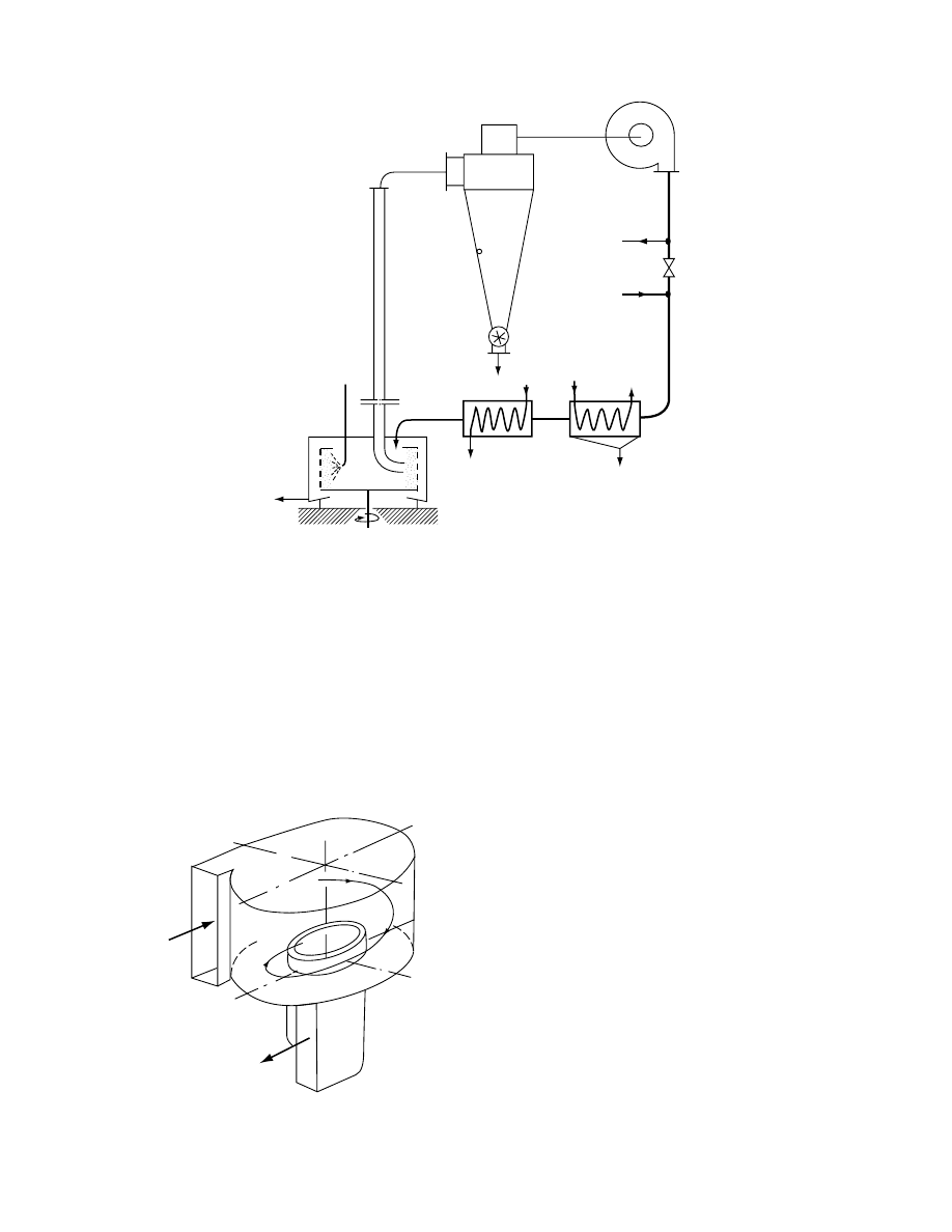
A fast stream of hot gas carryi ng suspended wet
particles is intr oduc ed tangent ially into the c hamber.
After severa l spins (i.e., he lical motion wi thin the
chamber) , the gas and mate rial escape throu gh a
centra l exhaust port and are separat ed in a cyclone.
A ch aracteris tic featu re of this type of dryer is that
only smal l pa rticles can be carried away as large wet
particles are throw n by the centrifugal force toward
the peripher y. Thi s type of dryer can be designe d to
obtain a fina l pro duct of requir ed particle size. To he lp
disintegra te the large pa rticles, mechani cal impac t
disintegra tors are often built into the drying ch amber.
29.4.2.4.2 Spin-Flash Dryers
The princip le of separat ion of wet and dry pa rticles is
applie d in the design of a spin-fla sh dryer for sticky
and pastel ike mate rials (
). In the bot tom
of a cylin drical chambe r a high-spe ed impeller disin -
tegrates the wet feed in a rapid stream of the tangen -
tially intr oduced he ated gas stream. The swirl ing ga s
carries away dry particles , which are then separated in
a cyclone. Par tially dried particles fall back into the
impeller zone and are disi ntegrated. This type of dry er
is especia lly suit able for thick pa stes as it can hand le
them wi thout dilut ion.
29.4.2.4.3 Countercurrent Spin Dryers
In a countercur rent spin dryer, a princi ple of two
coaxial cocurrent swirls of gas is applie d. An exem-
plary drye r scheme worki ng accordi ng to this prin-
ciple is shown in
. The cyli ndrical chamb er
is equipped with a series of side ports that introduce
air tangentially into the chamber. The velocity of the
side airstreams varies in the range of 5–100 m/s and is
capable of producing a looser or tighter spiral, or
finally a stationary circular motion of the entrained
2
1
Bleed
3
Make-up
nitrogen
Coolant
Steam
Feed
6
5
4
Solvent
FIGURE 29.5 Closed-cycle pneumatic dryer in conjunction with a centrifuge (1, dryer tube; 2, cyclone; 3, blower; 4,
condenser; 5, heater; 6, centrifuge).
FIGURE 29.6 Schematic of a convex dryer.
ß
2006 by Taylor & Francis Group, LLC.
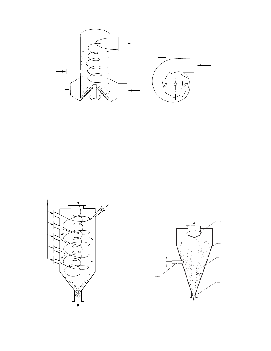
particles depending on the side nozzle inclination and
gas velocity. In this way particle residence time can be
controlled. Wet solids are introduced at the top of the
dryer chamber. Drying occurs as the solids descend
and finally separate from the gas, leaving the chamber
through a bottom port equipped with an airlock.
29.4.2.5 Spouted Bed Dryers
A spouted bed is essentially a conically shaped cham-
ber with a cylindrical section on top supplied with air
through a single nozzle at the bottom (Figure 29.9).
The operational regime of the spouted bed dryer
depends on the properties of feed and the assumed
final product requirements. Polydisperse, slow-drying
granular materials are continuously added and re-
moved from the bed. Particles that undergo severe
attrition or dramatically lose weight when dry can
be carried away from the chamber with the heat
carrier. Product size and moisture content are thus
controlled by superficial air velocity in the cylindrical
part of the drying chamber. Pastelike materials can be
sprayed onto a spouted bed of inert material. Owing
to severe attrition the dry product is removed from
the particles and carried away with gas for collection
in a separator.
Feed
A
A
Air
Air
Product
A-A
FIGURE 29.7 Schematic of a spin-flash dryer.
Product
Feed
Vapors
Air
FIGURE 29.8 Schematic of a countercurrent spin dryer.
3
5
1
2
4
FIGURE 29.9 Schematic of a spouted bed dryer with an
inert bed (1, shell; 2, nozzle; 3, particle separator; 4, spray
nozzle; 5, inert bed).
ß
2006 by Taylor & Francis Group, LLC.

29.4.2 .6 Vib rated Bed Dry ers
For highly polyd isperse or stic ky produc ts with long
drying times, the vibrat ed bed type of dryer offers the
possibi lity of co ntinuous operatio n accompani ed by
gentle mate rial hand ling and unifor mity of the fina l
produc t mo isture con tent. A trough vibrating in a
direction sligh tly inclined to the verti cal at frequenci es
up to 60 Hz an d amplitudes up to severa l mil limeter s
offers the pos sibility of sim ultane ous mate rial trans -
portation and vigorou s mixing. In such a dryer,
granula r mate rial can be he ated directly from gas
blown through a perforated trough bottom or indir -
ectly from heatin g surfaces imm ersed in the be d. Vi -
brator y acti on reduces mate rial cohesion, which
makes this dryer suitable for very wet or sticky ma-
terials . Spiral constr uction of the trough ca n, if neces-
sary, extend the resi dence time of the mate rial up to
30 min. Thes e dryers can operate wi th virtuall y any
gas veloci ty up to the entrai nment lim it. The ga s
velocity can be ad justed to the particle size. In direct
drying cond itions, evaporat ion rates 30–100 kg/h
m
2
of grid area are obse rved. If the amou nt of hea t
carried with gas is not adequate for drying, additio nal
contact he aters can be employ ed.
Radi ant heati ng by infrared rad iation (IR) radi-
ators can also be used . How ever, in this case onl y very
thin be ds can be unifor mly he ated. For gluta mic acid
with mate rial load 15 kg/m
2
and rad iant heat flux 3.5
kW/m
2
, evaporat ion rates up to 4.5–9 kg/m
2
h have
been observed.
29.4.2 .7 Flui d Bed Dryers
Continu ous fluid bed dryers are generally built in two
version s: vessel-l ike ideal ly mixe d dryers and trough-
like plug-flow dryers . Perfectly mixe d fluid bed dryers
are charact erized by a rapid decreas e of the feed
moisture co ntent as it is diluted in the large vo lume
of the relative ly dry bed . Therefor e, they can han dle
relative ly high init ial mo isture co ntent feedstock .
Trough dryers are much more sensi tive to initial
feed moisture con tent since the solid ’s mois ture de-
crease s gradual ly with dryer lengt h. As expecte d, they
provide a much bette r resid ence tim e dist ribution
(RTD) of soli ds in the dryer. Fluid bed dryers can
be built virtu ally in any requir ed scale . Besides dr ying
they can be used for cooling and g ranulation. Thei r
modificat ions, such as vibrated, stirred, and pulsed
fluid beds, can be used to dry or process polydisp erse
and relative ly sti cky material s.
29.4.2 .8 Sp ray Dry ers
Solutio ns and thin slurries of dru gs can be spray dr ied
by con tact with hot air. Par ticles of dry produ ct
obtaine d in such a way are very fine , so after mixing
with oth er compo nents and granu lation they can be
used directly for tableting . W hen the spray drying
operatio n is cocurrent , that is, hot a ir is intro duced
into the dryer close to the atomizing device, there is
no da nger of ov erheat ing as evapo ration rates are
high (34–16 0 kg/h
m
2
of particle area) . Thus , highly
heat-sensi tive mate rials can be spray dried.
A typic al arrange ment of an open -cycle spray
dryer for pharmac eutic als is shown in
.
Gas–liqui d nozzles are commonl y used to spray feeds
that are solut ions. How ever, in the produ ction of
certain pharmac euticals, such as antibioti cs, the pow-
ders obtaine d by spray dr ying low -concent ration
aqueou s solut ions have low bulk den sity. Highe r
bulk density can be obtaine d if the feed is partly
precipitat ed. High bulk density antibi otics are pro -
duced from suspen sions of precipitat ed substrates in
organic solvent s; this requires the use of a closed- cycle
dryer to recuperat e the solvent an d also an inert ga s
as drying medium to avo id the risk of ignition. Se v-
eral pharmac eutic al prod ucts after filtrati on form
pastes that can be spray dried if they are pum pable.
Pastes that are too thick must be thinned wi th solv-
ents or by disi ntegra tion of their struc ture, as in the
case of thixot ropic pa stes. Fro m a prac tical point of
view, disk atomizers are bette r capable of han dling
thicke r pastes than are two -fluid noz zles.
In many cases, when inert ga ses are used for dry-
ing or valuabl e solvent s must be recover ed, a closed-
cycle dryer can be designe d ac cording to the rules
explain ed in
29.4.3 I
NDIRECTLY
H
EATED
D
RYERS
29.4.3.1 Drum Dryers
Drum dryers are frequently used for drying slurries
and thin pastes, especially those that easily adhere to
the metal surface and therefore are difficult to dry in
other dryers. The slurry or paste is fed onto the drums
by means of various types of feeders. Some of the
standard feeding arrangements and recommendations
for their use are indica ted in
. The dry
product is removed by doctor blades. Depending on
the material properties, the product is removed in the
form of powders, flakes, or webs. The drum can be
entirely enclosed in a hood and supplied with the
necessary amount of drying gas. Thus, organic solvents
can be recovered in a closed-cycle operation.
29.4.3.2 Vacuum Dryers
Materials that are thermolabile or easily oxidizable,
especially when wet, can be dried in vacuum dryers.
ß
2006 by Taylor & Francis Group, LLC.
Feed
5
3
2
1
6
8
Product
7
9
4
FIGURE 29.10 Spray dryer installation (1, drying chamber; 2, atomizer; 3, air dispenser; 4, air heater; 5, feed pump; 6, main
cyclone collector; 7, wet scrubber; 8, pneumatic conveying system; 9, conveying cyclone). (Courtesy of A/S Niro Atomizer,
Soeborg, Denmark.)
3
1
1
4
4
3
2
3
2
1
1
1
2
2
1
3
3
4
3
3
4
4
1
1
3
3
1
1
4
4
2
3
4
1
(a)
(b)
(c)
(d)
(e)
(f)
FIGURE 29.11 Some standard feeding arrangements for drum dryers: (a) nip feed, suitable for thin solutions; (b) feed roll,
suitable for glutinous materials, such as starch; (c) double applicator roll, for heat-sensitive materials; (d) splash feed, used
for slurries; (e) dip feed, for suspensions; (f) multiple applicator roll, used for increasing film thickness (1, drums; 2,
applicator rolls; 3, doctor blades; 4, conveyors). (Courtesy of R. Simon and Sons, Basford, England.)
ß
2006 by Taylor & Francis Group, LLC.
Various types of vac uum dryers are in use for drying
pharmac eutic al prod ucts.
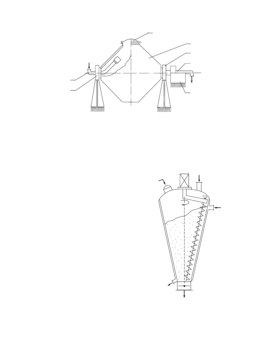
29.4.3.2.1 Double-Cone Dryer-Blender
Opera ted in batch mode, the doubl e-cone dryer-
blender dryer (F igure 29.12) is suitable for drying
wet granula r mate rials. Owing to the intens e blend ing
that occurs during the drying cycle, they can be
used for preparat ion of the table ting form ulatio ns.
Commerci al double-cone dry ers ha ve capacities up
to 10 m
3
. They may be glass lined to pro vide high
purity of the pro duct. They are especi ally suit able to
perfor m co nsecutive ch emical reaction-dr ying cycles .
Reage nts can be suppli ed throug h a feed tube or
through a hollow shaft. The heat necessa ry to eva p-
orate the mois ture is supplie d from steam-heat ed
dryer walls. Dryin g rates observed here are in the
range 2–7 kg /h
m
2
of the heated area.
29.4.3.2.2 Conical Dryer with Screw Mixer
The conical dryer with screw mixe r is sim ilar in prin-
ciple to the doubl e-cone dryer-blend er althoug h the
vessel is stationar y a nd solid s are mixed by epicycl ic
screw mixe r (Figur e 29.13) . For pressur es from 25 to
150 mbar an d wall tempe ratur es from 40 to 60 8 C,
Simon [6] report s evaporat ion rates of water up to
10 kg/h
m
2
. Units up to 5 m
3
are commer cially avail -
able. The dryer ha s no dead spaces and is easy to clean.
29.4.3.2.3 Paddle Dryers
Continu ously ope rated dryers of the pad dle type
(
) pro vide drying times up to severa l
hours. Suitabl e for pastelike an d granula r mate rials,
they are steam heated. A horizontal rotating shaft
fitted with paddles scrapes the product from the
walls and mixes and transports it along the dryer
length. Solvents can be fully recovered if a suitable
condenser for vapors is provided. Evaporation rates
of water up to 10 kg/h
m
2
are observed.
5
2
1
6
4
3
6
FIGURE 29.12 Double-cone batch vacuum dryer (1, steam jacket; 2, hatch; 3, drive; 4, vacuum ducts; 5, steam supply;
6, bearings).
4
6
3
5
2
1
FIGURE 29.13 Conical vacuum dryer with epicyclic screw
mixer (1, steam jacket; 2, hatch; 3, feed tube; 4, exit port and
valve; 5, motor; 6, drive arm; 7, mixing auger).
ß
2006 by Taylor & Francis Group, LLC.
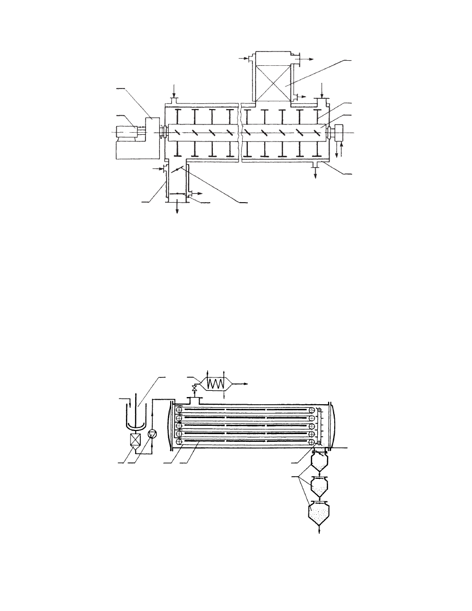
29.4.3.2.4 Vacuum Band Dryers
Vacuum band dryers are suitable for all types of
pastelike materials. Wet material is dried as it is
transported on a moving band. Heat is supplied by
infrared low-temperature radiators or by contact with
heated bands. A multiband vacuum dryer is shown in
Figure 29.15. To allow continuous production, such
dryers are equipped with an automatic discharge
system that prevents dehermetization of the dryer
chamber. Drying chambers that provide drying sur-
face areas up to 120 m
2
are available commercially.
29.4.3.2.5 Filter Dryer
The filter dryer is a combination of two operations in
one vessel. Usually it has a cylindrical form with
a bottom that serves as a filter. It is equipped with a
paddle agitator that can be heated internally or heat
may be transmitted through jacketed walls. In the
6
7
2
5
5
Product
2
3
4
Feed
Vapors
FIGURE 29.14 Continuous vacuum paddle dryer (1, vapor filter; 2, steam jacket; 3, shaft with paddles; 4, paddles; 5, valves;
6, shaft drive; 7, shaft oscillator).
1
6
2
3
4
5
7
8
FIGURE 29.15 Band vacuum dryer installation (1, feed mixer; 2, filter; 3, feed pump; 4, band; 5, heating panels; 6, vapor
condenser; 7, scraper; 8, product collector system).
ß
2006 by Taylor & Francis Group, LLC.

latter case, the vessel is turned ups ide down after
filtering. Units of filter area up to 15 m
2
a nd volume s
up to 22.5 m
3
are built .
29.4.3 .3 Freeze Dry ers
Freeze drying is the best method for drying highly heat-
sensitive or easy oxidizable materials. However, its se-
lection must be governed by economic considerations.
Early applications of this method were the drying of
blood plasma and serum during World War II.
The high cost of freez e-drying discour ages its
wider applic ation. In freez e-dryin g, solut ions of pha r-
maceut icals dos aged into vial s are frozen a nd placed
in a vacu um chamber. Ice su blimes, consumi ng the
latent heat of subli mation , suppli ed from heated
shelve s. Recently, micr owave he ating has also been
used in freeze dryers . The vapor is con tinuous ly re-
moved by a vacu um pump. After all mois ture su b-
limes, a very fine por ous struc ture remains that can be
easily rehydrat ed. It was notice d that solut ions di-
luted be low 1% (weight ) con centration of solids do
not prod uce such structure. The struc ture is labil e and
can colla pse if its tempe ratur e is raised ab ove a cer-
tain tempe ratur e of collap se. Thi s tempe ratur e can be
as low as
40 8 C (e.g., for glucose a nd fructo se) or
10 8C (e.g., for starches an d protei ns) an d increa ses
with the increa se of molec ular weight of the lattice
and its dryn ess. To pro tect agains t even slight rehydra-
tion the freez e-dried vial s are immed iately stopp ered,
prefera bly by internal devices without deco mpression
of the chamber.
Among othe r requ irements that freez e dryers for
pharmac eutic als have to fulfil l, the a ctual trend is
that they shou ld provide the followin g range of per-
forman ce parame ters (Table 29.4) [7]. Und er the
conditi ons refer red to as nor mal, most of the pha r-
maceuticals can be dried. Under normal conditions,
with shelves fully covered with vials at an operating
temperature of 608C, a drying rate of about 1 kg/m
2
h
may be expected. Peak evaporation rates can reach
1.5 kg/m
2
h for an operating temperature of about
708C. Because of the critical drying conditions met
during drying of pharmaceuticals, the whole drying
system (
) and its componen ts must meet
the following requirements:
Chamber: Should if possible be built of easy-to-
clean and noncorrosive materials and provided
with a vial-stoppering facility.
Shelf heating and cooling: In order to protect
against product melt-back, dryer shelves must
be frozen during loading and chamber evacu-
ation. Further, during drying they must be
heated, preferably with the possibility of tem-
perature control.
Vacuum pump: In a typical dryer with the shelf-
freezing feature, the vacuum pump should have
a capacity of about 50 L/s
m
2
of the shelf area.
As leakage of air is inherent in any practical
vacuum system, this capacity is used to main-
tain the desired operating pressure. If, however,
the shelves do not have the freezing capacity,
the vacuum pump should have a much higher
capacity to provide nearly instantaneous dryer
evacuation.
Condenser: All freeze dryers are equipped with
condensers to remove water vapor from the
gases coming out of the drying chamber.
Instrumentation and control: Provide monitoring
and control of pressure and temperature at stra-
tegic points in the dryer, which includes the
control of shelf temperature and often the
vacuum if product sublimation is possible.
Only the most sensitive and expensive products
are usually freeze-dried. Among these are antibi-
otics, antitoxins, antisera, certain vitamins, cancer
chemotherapy drugs, diagnostic reagents, and other
unstable and easily oxidizable materials. Because of
the high value of the dryer load, they are often
equipped with standby vacuum pumps and re-
frigeration units, as well as a standby electrical
power supply and control instrumentation to protect
against any failure.
TABLE 29.4
Performance Parameter Ranges for Pharmaceutical
Freeze Dryers
Parameter
Normal
Conditions
Special
Conditions
Chamber pressure (mmHg)
Peak
100–200
50
Final
20–50
5–10
Shelf temperature (8C)
Lowest
40
50
Highest
70
80
Shelf heat-up rate (min),
from
408C to 708C
90
60
Shelf cool-down rate (min),
from 228C to
448C
90
60
Evacuation rate (min) to
reach 100 mmHg
15–30
5–10
Vapor handling capacity
(kg H
2
O/h
m
2
)
0.98
1.47
Total shelf area (m
2
)
11–25
0.75–3.5
ß
2006 by Taylor & Francis Group, LLC.
29.4.4 G
RANULATION AND
D
RYING
To ha ve proper solubi lity the table ts are form ed from
very finely dispersed dru g mixtures. How ever, the
process of tableting is not smoo th if these powder s
are fed direct ly to the table ting machi nes. Granul a-
tion of the powder s before table ting is usually re-
quired. Also, several pharmac eutic al pro ducts, such
as gluco se prepa rations, a re sold in gran ulated form .
Granu lation may be carried out as a dry or a wet
process . Aggl omerat ion of parti cles of very fine (i.e.,
few micromet ers in size) dry powder s can occur owing
to van der W aals forces of attracti on. Aspirin, acet-
ophen etidin, thiamine hydro chloride, ascorbi c acid,
and others can be g ranulated using a dry pr ocess.
For wet granu lation, a suitab le liquid is sprayed
onto the vigorou sly mixe d powd er. Adhesi on of par-
ticles takes place owin g to the developm ent of liquid
bridges and capillary forces betw een parti cles. In the
drying pha se followi ng the granula tion process , solid
bridges de velop owi ng to cryst allization of dissolved
substa nces.
Spr ay granula tion may be c arried out in fluid bed s
or vibrated fluid beds as a separat e process , or this
may be perfor med in the dryer its elf as the fina l stage
of the drying process .
cation of a vibrat ed fluid be d dryer as a secon d stage
of a combined drying and granula tion process . In
the first stage the mate rial is spray dried. Resid ual
moisture is remove d from the powder in a vibrated
fluid bed dryer. In the same dryer the powder is sp ray
granula ted and the granule s are dried to the requ ired
final moisture content .
In an alte rnate method of agglom eration , satur -
ated steam is blow n for a specific period of time
through the fluid bed of cold pa rticles. Cond ensation
of moisture on the particles form s agglom eration c en-
ters and allows form ation of granule s of the produ ct
during fluidiza tion.
29.5 DRYING OF DOSAGE FORMS
Final drug form ulation is a mixt ure of active dru gs
with a su itable excipi ent and necessa ry additive s
(binder , color, aroma, etc. ). The mixtu re may be
obtaine d directly through spray drying of solution
or suspensi on; otherw ise, crystall ine substa nces must
be carefully grou nd and blended. Pow dered prepar-
ation is usually converted into granules, tablets, or
dragees. Granules obtained by wet granulation re-
quire postgranulation drying, which may be per-
formed in the same unit (see Sectio n 29.4. 4). Tabl ets
usually do not require drying although they contain
some water that was present in powder to im-
prove tableting. Dragees, which are essentially lac-
quered tablets, need drying as a final stage. Their
coating is sprayed usually in many layers, including
8
8
9
5
4
3
2
1
6
7
10
FIGURE 29.16 Freeze-drying system (1, drying chamber; 2, heated or cooled shelf; 3, ice condenser; 4, diffusion vacuum
pump; 5, rotary vacuum pump; 6, tank for cooling shelf circulating liquid; 7, tank for heating shelf circulating liquid;
8, freezing aggregate; 9, circulation pump; 10, air filter).
ß
2006 by Taylor & Francis Group, LLC.
an an tioxidant layer , dissolv ing rate-limit ing layer ,
and tast e and co lor layer . Coating layer s may be
water or solvent ba sed. Drage es may be dr ied in a
batch dryer with flow of air through the bed or in a
continuous fluid be d. These dryers are integral parts
of dra gee-coa ting machi nes.
29.6 SOME TECHNOLOGICAL DATA
ON DRYING OF PHARMACEUTICAL
PRODUCTS
The following is a short summa ry of some techni cal
informat ion on drying of some of the more com-
monly encoun tered pharmac euticals and inter media te
produc ts.
present s a su mmary of the va rious
types of dr yers, toget her with exampl es of pharma-
ceutica l prod ucts for whi ch they are used commer -
cially. It should be noted that in most ca ses alte rnate
dryers are used in practice to dry the same pro duct.
Typical ope rating data for drying of selec ted pharma-
ceutica ls are given in
. The infor mation
contai ned in Table 29.6 is derive d from ope rating
dryer perfor mance data as well as from laborat ory-
scale experi ments. Labor atory an d often pilot-sc ale
tests are necessa ry before a co mmercial -scale dry er
may be designe d wi th confid ence. For pharmac eutic al
products , labo ratory tests are perfor med to provide
data on the thermal sensitiv ity, oxidiz ability, stabi lity,
and fina l product mois ture content . This forms the
basis for the selec tion of a dryer and process param-
eters. If the product is pro duced in small quantities , a
batch dryer may be selec ted. In large -scale produ c-
tion, energy losses, losse s due to deterio ration of the
product qua lity, and other losse s can be quite sub -
stantial if the dryer type and operati ng parame ters
are not optim ally selected. To show how the drye r
type influen ces the drying kineti cs, severa l drying
rate curves for selected pha rmace uticals are present ed
in
29.7 ASEPTIC CONDITIONS IN
PHARMACEUTICAL DRYERS
The prob lem of maint aining asep tic condition s exist s
in all stage s of pharmac eutic al prod uction. The fina l
stages of the pharmaceutical production process, dry-
ing, tableting, and packaging, are especially suscep-
tible to microbial infection. High-sterility standards
are required for pharmaceuticals of biologic origin,
standards, laboratory reagents, and others. The two
possible sources of bacterial infection during drying
Solution
Hot air
1
Vapors
2
3
Vapors
Agglomerizing
liquid
Product
Cool air
Hot air
FIGURE 29.17 Combined spray drying–agglomerating system (1, spray dryer; 2, cyclone; 3, vibrated fluid bed dryer-
granulator).
ß
2006 by Taylor & Francis Group, LLC.

are the feed and air used for direct dry ing. Prop er
sanitary han dling of the feed must be maintained
throughou t the whole producti on cyc le. If the drug
is not thermo degradabl e, sterilizati on by sup erheat ing
can be applied . If the fina l pro duct is thermolabi le,
therma l ster ilization of the raw mate rials somet imes
can be ap plied or chemical, ultr aviolet, or radioac tive
means of ster ilization shou ld be used .
For all high-s terility manufa cturi ng operatio ns,
class 100 air cleanl iness acc ording to U.S. Fede ral
Standard 209A (1966) must be maintained. High-
efficien cy air filtrati on and lami nar flow units must
be inst alled in packaging areas. Rem oval of the
airbor ne micr obes from the air that feeds the dryers
and pack aging areas is usually perfor med by
high-e fficiency particu late air (HEP A) filter s. They
are claimed to remove up to 99.97% of all pa rticles
larger than 0.3 mm, that is, most of the known bacter ia
(but not viruses).
To protect HEPA filters against premature clog-
ging, air filtration is usually multistage. At least one
prefilter is added to remove dust from the air before it
enters the HEP A filter .
matic diagram of a typical aseptic spray dryer system.
If drying is performed at low temperatures, air
washing with sterilizing liquid also may be used.
This is also applicable to air supplied to the packag-
ing areas. Prewashing of the air with antibac-
terial liquids can remove up to 95% of all viable
microorganisms present.
TABLE 29.5
Applications of Different Pharmaceutical Dryers
Type
General Application
Example Product
Directly heated
Fixed bed
Ovens
Small batches of all types of pharmaceuticals
Various products
Band dryers
Organic raw materials, preformed pastes
Various products
Turbo-shelf dryers
All kinds of medium and coarse granular materials with
long drying times
Penicillin, ascorbic acid, mannitol,
monosodium glutamate, nicotinic acid,
riboflavin, sorbitol, starch
Suspended state
Pneumatic dryers
Removal of unbound moisture, narrow particle size
Ascorbic acid, hydrate of 2-keto-
L
-gluonic
acid, p-aminobenzosulfamide, tetracycline
sulfathiazole, aminopyrine, ASA
Cyclone dryers
Removal of unbound and bound moisture, possible
self-adjustment of particle size, longer residence times
than in pneumatic dryer
Thiamine bromide, phthalimidopropionitrile,
ascorbic acid, folic acid, nicotinic acid
Spouted bed dryers
Long drying times, increased thermal sensitivity, suitable
for drying pastes on inerts
ASA, hexamethylenetetramine, 2-amino-5-
ethyl-1,3,4-thiodiazole
Vibrating bed dryers
Granular polydisperse materials, long residence time
Nicotinic compounds, sorbose, ascorbic acid,
lactose
Fluid bed dryers
Medium and coarse granular materials, possible
granulation
Vitamins, lactose, glucose, sodium glutamate,
Urotropin, antibiotics (oxytetracycline),
paracetamol, pancreatin powder, ASA
Spray dryers
Pastes, solutions, and suspensions
Aminosalicyclic acid, bacitracin, blood plasma,
blood serum, methicillin salts, culture media,
dextran, enzymes, gamma-globulin,
hormones, streptomycin, iron dextran,
lysine, casein hydrolysate, penicillin, serum
hydrolysate, penicillin, serum hydrolysate,
tetracycline vitamins, oleandomycin,
chloramphenicol succinate salts
Indirectly heated
Drum dryers
Thin pastes and slurries
Calcium panthothenate, streptomycin sulfate
Vacuum dryers
All types of heat-sensitive materials
Various products
Freeze dryers
Extremely heat-sensitive materials in solutions and
suspensions
Antisera, antibiotics, antitoxins, vitamins,
cancer chemotherapy drugs, various
diagnostic reagents and standards
ß
2006 by Taylor & Francis Group, LLC.

TABLE 29.6
Process Parameters for Drying of Selected Pharmaceuticals
Material
a
Dryer Type,
Bed Height
Moisture
b
Initial
Moisture
Content
(310
2
kg/kg)
Final
Moisture
Content
(310
2
kg/kg)
Initial Air
Temperature
(
˚
C)
Final Air
Temperature
(
˚
C)
Dryer
Throughput
(kg/h)
Evaporation
Rate
(kg/m
2
h)
Residence or
Drying
Time
Unit Air
Consumption
(kg air/kg material)
AET
Batch fluid bed
17–18.6
0.5
150–155
Batch fluid bed,
100 mm
20–23.5
0.5–1
90–95
Batch fluid bed,
100 mm
110–115
Aminopyrine
Combined
d
15
0.68
95
45
86
83
c
Antibiotics
Batch fluid bed
19.3
0.8
70
80 min
ASA
Batch fluid bed
15
1
40
20 min
Ascorbic acid
Combined
6.34
0.06
170
60
35.7
Vortex
Ethanol
12
0.35
90
55
45 s
10.3
Azorybitylamine
Combined
50
0.5
160
65
252
Barbituric acid
Combined
30
0.2
250
65
109.7
Biomycin
Pulsed fluid bed
25–48
0.05
1–1.5 h
DKGA
Combined fast
spouted bed
15
0.5
45
38
65.3
117
c
11
0.2
55
10 s
Folic acid
Vortex
20
0.4
80
50
52 s
10.6
Nicotinic acid
Combined
20.9
0.005
100
60
Vortex
20
0.55
120
80
36 s
16.6
Vortex
27
0.34
130
78
38 s
15.0
ß
2006
by
Taylor
&
Francis
Group,
LLC.

Vortex
28
0.54
130
80
42 s
14.0
Vortex
27.6
0.36
150
98
57 s
13.6
Vortex
27.8
0.43
160
105
62 s
12.0
Oxytetracycline
Pulsed fluid bed
18–24
3–5
1.5–2 h
Phthalimidopropionitrite
Vortex
18
0.3
80
52
45 s
10.2
Piperazine
Combined
30–5
5–0.5
90–160
50–80
40–79
30–50
c
Riboflavine
Combined
40
0.75
130
80
150
Sorbose
Combined
6
0.2
124.7
32.8
62.7
29.2
Sulfaguanidine
Pneumatic
14.8
8.93
0.3–0.5 h
Terpin hydrate
Pulsed fluid bed
20–28
0.1–0.3
130
50
80.1
58.8
c
Tetracycline
Combined
30
18
130
20
Pneumatic
30–35
15–12
0.3–0.35 h
Granulated
Pulsed fluid bed
24–26
12–14
0.4–0.5 h
Hydrochloride
Pulsed fluid bed
17–21
1–2
Thiamine bromide
Vortex
Ethanol
15
2
65
46
16
1.8
80
50
38 s
13
18
1.5
90
55
36 s
12
20
0.6
100
70
23 s
11
20
0.4
100
75
42 s
10
Vitamins
Turbo-tray
20
5
90
30 s
8
a
AET, 2-amino-5-ethyl-1,3,4-thiodiaz ASA, acetylosaloicyclic acid; DKGA, hydrate of 2-keto-
L
-gluonic acid.
b
Moisture removed is water if not otherwise indicated.
c
In kg air/kg water evaporated.
d
Free fall of extruded particles in countercurrent with air and fluid bed.
ß
2006
by
Taylor
&
Francis
Group,
LLC.
12
10
3
2
1
5
8
6
4
2
8
7
3
5
2
1
6
5
4
3
2
1
X
,%
X
,%
8
4
40
2
(b)
X
,%
4
6
8
10
4
12
20
28
40
8
X
,%
N
, %/min
6
4
3
2
1
2
4
4
3
2
1
5
6
8
X,%
4
2
4
80
120
t, min
36
44
t, min
60
80
4
(a)
t, min
16
4
1
3
5
4
N
, %/min
12
8
4
4
8
12
16
X,%
t, min
FIGURE 29.18 Drying kinetic data for (a) penicillin; (b) ascorbic acid (1, countercurrent spin dryer; 2, flash dryer with
impacting streams of gas; 3, spouted bed dryer; 4, gas filtration in stationary bed; 5, fluid bed; X, moisture content; t, time; N,
drying rate).
4
5
6
10
11
7
3
6
1
7
2
8
9
9
4
Drying
air
Atomizing
air
Exhaust
air
Feed
Pro-
duct
FIGURE 29.19 Aseptic open spray drying system (1, drying chamber; 2, air dispenser; 3, atomizer; 4, prefilter; 5, filter;
6, heater; 7, HEPA filter; 8, sterile feed filter; 9, feed pump; 10, cyclone collector; 11, packing room). (Courtesy of A/S Niro
Atomizer, Soeborg, Denmark.)
ß
2006 by Taylor & Francis Group, LLC.
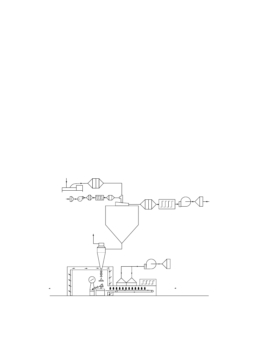
The packaging areas should be provided with
laminar flow units supplied with filtered or washed
air. All personnel and ancillary equipment must be
placed downstream from the sterile product. A sche-
matic of the packaging area of a typical spray dryer
for aseptic operation is shown in Figure 29.20. In
general, for aseptic noncontaminating drying oper-
ation, rotating or sliding parts should be avoided in
dryer installations. Dryers themselves and their duct-
work can be easily sterilized by maintaining the in-
stallation at elevated temperatures for specified
periods. The U.S. Pharmacopoeia specifies heating at
160–1708C for 2–4 h. However, most aseptic dryers
are sterilized at temperatures in the range 200 to
2508C for several hours in practice.
Effectiveness of thermal sterilization may be
tested by placing samples of test bacteria (Bacillus
subtilis for hot air and spores of Bacillus stearother-
mophilus for steam sterilization) in strategic locations
in the installation. After sterilization, samples are
sown onto culture media in petri dishes and observed
for growth. Absence of any growth indicates that
sterilization was successful.
To maintain high-purity standards of the product,
several precautions must also be taken in the design of
the drying chamber and installation [8].
The installation must be leakproof and must op-
erate under slight overpressure.
All inside surfaces must be as smooth as possible;
all corners must be rounded to guard against
material deposition.
All ductwork should be as short as possible to
prevent product buildup.
All locations where mechanical friction of parts
take place should be eliminated as they can
produce small metallic contaminations in the
product. Rotating or sliding parts should be
avoided.
Aseptic dryers with an open drying cycle provide
satisfactory protection against microbial infec-
tion. Nevertheless, closed-cycle dryers offer a
much better possibility of maintaining proper
sanitary conditions. Unfortunately, their higher
costs make them justified only in some special
cases.
Bottles out
Bottles in
Filling machine
Clean room with
laminar flow
Bottle sterilizer
Fan
Pre-filter
Hepa filter
Cyclone
Outlet air
Atomizing air
Feed
Feed pump
Pre-filter I
Pre-filter II
Hepa filter
Two fluid nozzle
Sterile feed filter
Air blower
Heater
Hepa filter
Heater
Fan
Pre-filter
Drying air
Drying chamber
FIGURE 29.20 Aseptic spray dryer and packaging area. (Courtesy of A/S Niro Atomizer, Soeborg, Denmark.)
ß
2006 by Taylor & Francis Group, LLC.

29.8 SOLVENT RECOVERY AND
CLOSED-CYCLE DRYING
A large por tion of all pharmac eutic als is obtaine d
from nonwat er solutions. The solvent is eithe r a single
compon ent solvent (i.e., ethanol , methan ol, acetone,
etc.); howeve r it is often a mixtu re of solvents. Table
29.7, contai ning some infor matio n selec ted from
Pakowski [9], present s exempl ary drugs with mois ture
that is a solvent mixture.
These solvents, due to their high cost and detrimen-
tal influence on the environment, may not be disposed
off into atmosphere even at very low concentrations. In
vacuum dryers solvent vapors after filtering in dust
collectors undergo condensation in single or multistage
condensers. In convective drying the presence of solv-
ents and powders can produce an explosive mixture
with air, which calls for inert gas as the heat carrier. It
is then necessary to close the drying cycle.
In closed- cycle drying the spent gas, after separ-
ated from the dried mate rial, is dehu midified and
after reheat ing retur ned to the dryer.
A closed-cycl e dr yer is justified in the foll owing
cases:
Flamm able, toxic, or valuabl e organic solvent
is used. In this case the solvent will be fully
recuperat ed.
Inert gas is used as drying medium , which is
recomm ended if flamma ble solvent or soli d is
dealt wi th. Easy ox idization of the pro duct also
requir es inert gas drying.
Solids or its solvent or vapo rs produ ced during
drying are toxic , ha ve an unpleasa nt odor , or
can by other means pollut e the atmos phe re.
Inert gas, usu ally nitr ogen, c irculatin g in the cycle
is co ntinuous ly suppli ed with a fresh mak eup gas. For
a spray dryer with evaporation rate of acetone, 110
kg/h, approximately 3 m
3
/h makeup nitrogen is ne-
cessary during normal operation. Purging of the in-
stallation after washing and sterilization requires
approximately 75 m
3
nitrogen.
A closed-cycl e spray dryer is shown in
. Essenti ally the same elem ents of installation
are used as for normal open-cycle dryers; however,
disk or liquid-nozzle atomizers are preferred as they
do not require gas for spraying. Solvent evaporates
into the stream of inert gas, usually nitrogen, leaving
the material dry. Most of the particles then formed
are separated in the dryer; the rest are recovered in
high-efficiency cyclones. Hot and humid effluent gas
is contacted with cooled solvent in a scrubber where
the solvent vapors partially condense. Dehumidified
gas is reheated and returned to the dryer. Another
solution for water-based solids is a self-inertizing
TABLE 29.7
Some Pharmaceuticals Containing Multicomponent Moisture
Solid
Moisture
Composition, wt%
Total Moisture Content, wt%
Initial
Final
Raw vitamin C
1,2-Dichloroethane
68
20
0.1
Trichloroethylene
20
Acetone
10
Ethanol
2
Commercial vitamin C
Methanol
Water
Vitamin B6
Ethanol
80
10.6
0.5
Water
20
Dibromobenzene
Acetic acid
11
20
0.3
Water
89
Pancreatin
Acetone
60
0.3
Water
Trichloroethylene
Steroids
Methanol
30
0.2
Ethanol
Water
Multivitamin
Ethanol
85
13
1.5
Water
15
Antibiotics
Isopropanol
40
0.3
Acetone
ß
2006 by Taylor & Francis Group, LLC.
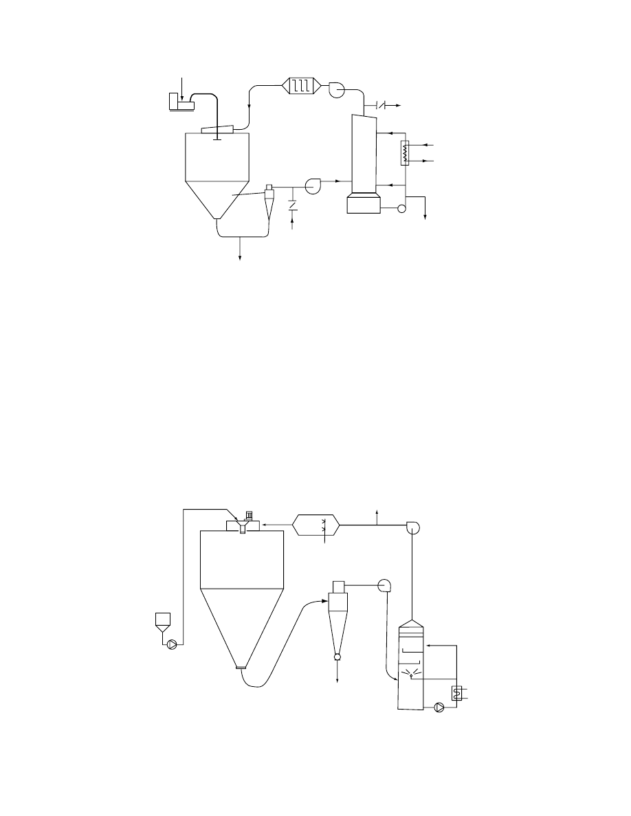
dryer (Figure 29.22) in which oxygen concentration in
drying air is lowered to 4–5% in a directly fired
gas heater.
The throughput of closed-cycle dryers is generally
limited by the volume of the scrubber used for cooling
and condensation. The dimensions of the scrubber
increase with the amount of gas used for drying;
however, closing the cycle of even such extensively
gas-consuming dryers as pneumatic or fluid bed
dryers was found justified.
Among the pharmaceuticals dried in closed-cycle
spray dryers, antibiotics and antibiotic by-products
can be mentioned. Coating of powders with poly-
meric coating material dissolved in the feed or so-
called microencapsulation is a new application of
closed-cycle spray dryers. For dryers using very
high gas flow rates, such as fluid bed dryers, the
following principle may be used. The outcoming
gas from the drying chamber is split into two
parts. One part is heated and recirculated whereas
the second part is sent to a condenser; after solvent
removal it is mixed with the recycle stream and
returned to the drying chamber. This allows oper-
ation at high gas flow rates in the drying chamber
Feed
10
2
1
4
5
3
9
6
8
7
Solvent
recovery
Product
Cooling
liquid
FIGURE 29.21 Closed-cycle spray dryer system (1, drying chamber; 2, atomizer; 3, gas dispenser; 4, cyclone collector; 5, inert
gas supply; 6, scrubber-condenser; 7, heat exchanger; 8, vent for purging dryer; 9, gas heater (indirect); 10, feed pump).
(Courtesy of A/S Niro Atomizer, Soeborg, Denmark.)
1
6
10
3
8
4
3
2
FIGURE 29.22 Self-inertizing closed-cycle dryer (1, feed tank; 2, direct heater; 3, atomizer; 4, atomizer drive; 5, scrubber;
6, drying chamber; 7, pumps; 8, cyclone; 9, fans; 10, cooler). (Courtesy of APV Pasilac Anhydro, Soeborg, Denmark.)
ß
2006 by Taylor & Francis Group, LLC.
and also relatively high solvent concentrations in
the exit streams, which makes condensation more
efficient. In the falling rate period, when the concen-
tration of the solvent in the exit gas decreases, re-
moval of moisture usually requires lowering the
temperature of the cooling medium in order to ob-
tain condensation at the required concentration of
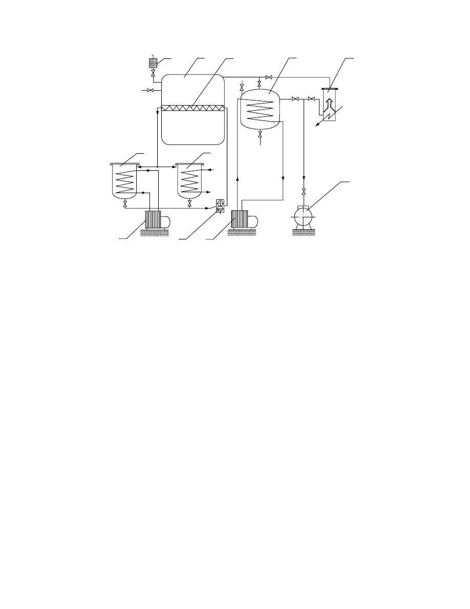
solvent. Figure 29.23 shows schematically a batch
fluid bed dryer working in a closed-cycle opera-
tion [10]. Two condensers operating at different
temperatures are used; this arrangement is espe-
cially appropriate when condensing a mixture of
two different solvents.
Traces of solvents in gas vented to atmosphere
from closed-cycle dryers are usually removed by in-
cineration in gas or catalytic burners. This method
may also be used for deodorization of exhaust gas.
Chlorine-containing solvents cannot be burned and
must be adsorbed on a suitable sorbent.
ACKNOWLEDGMENTS
We are grateful to A/S Niro Atomizer and APV
Pasilac Anhydro, both of Soeborg, Denmark, and
R. Simon and Sons, Basford, England, for granting
permission to reproduce some of their copyrighted
material.
REFERENCES
1. Basic Standards of Good Manufacturing Practice for
Pharmaceutical Products, Document PH 3/83, EFTA
Secretariat, Geneva, 1983.
2. L.G. Golubev, B.S. Sazhin, and E.R. Valashek, Drying
in Chemicopharmaceutical Industry, Meditsina, Mos-
cow, 1978 (in Russian).
3. J.P. Remington, Remington’s Pharmaceutical Sciences,
16th ed., Mack Publishing Company, Easton, 1980.
4. S.M. Reprintseva and N.V. Fedorovich, New Methods
of Thermal Processing and Drying of Pharmaceuticals,
Nauka i Tekhnika, Moscow, 1979 (in Russian).
5. P.H. Stahl, Feuchtigkeit und Trocken in der pharmaceu-
tischen Technologie (Moisture and Drying in the Pharma-
ceutical Technology), Dr. Detrich Steinkopff Verlag,
Darmstadt, 1980 (in German).
6. E. Simon, Industrielle Trocknung von Arzneimitteln
und ihren Vorstufen (Industrial Drying of Drugs and
Their Intermediate Products). In Trocknung und Trock-
ner in der Produktion, Vol. 3 (K. Kro¨ll and W. Kast,
Eds.), Springer-Verlag, Berlin, 1989 (in German).
7. S.L. Morgan and M.R. Spotts, Pharmaceutical Tech-
nology, 11 1979, pp. 94–101, 114.
8. K. Masters and I. Vestergaard, Process Biochemistry, 1
1975, pp. 3–6.
9. Z. Pakowski, Drying of solids containing multicompo-
nent moisture. In Advances in Drying, Vol. 5 (A.S.
Mujumdar, Ed.), Hemisphere Publishing Company,
New York, 1992.
10. E.I. Simon, Khim. Farm. Zhurn., 11 1978, pp. 121–128.
2
1
7
3
4
5
5
6
Feed
FIGURE 29.23 Closed-cycle batch fluid bed dryer (1, drying chamber; 2, bag filter; 3, blower; 4, heater; 5, condenser;
6, pump; 7, product collector).
ß
2006 by Taylor & Francis Group, LLC.
Document Outline
- Table of Contents
- Chapter 029: Drying of Pharmaceutical Products
- 29.1 Introduction
- 29.2 Classification of Pharmaceutical Products with Respect to Dryer Selection
- 29.3 Properties of Pharmaceutical Products
- 29.4 Dryer Types and Their Performance
- 29.5 Drying of Dosage Forms
- 29.6 Some Technological Data on Drying of Pharmaceutical Products
- 29.7 Aseptic Conditions in Pharmaceutical Dryers
- 29.8 Solvent Recovery and Closed-Cycle Drying
- Acknowledgments
- References
Wyszukiwarka
Podobne podstrony:
039 Drying of Biotechnological Products
034 Drying of Textile Products
030 Drying of Nanosize Products
the illict preparation of morphine and heroin from pharmaceutical products containing codeine homeba
Modeling with shrinkage during the vacuum drying of carrot (daucus carota) (Arévalo Pinedo, Xidieh M
Influence of drying methods on drying of bell pepper (Tunde Akintunde, Afolabi, Akintunde)
[Mises org]Hülsmann,Jörg Guido The Ethics of Money Production
Far infrared and microwave drying of peach (Jun Wang, Kuichuan Sheng)
ecdltest, produkty ryżowe, List of Rice Products in Stock
Microwave Application in Vacuum Drying of Fruits (Drouzaf, H SchuberP)
Microwave vacuum drying of model fruit gels (Drouzas, Tsami, Saravacos)
acetylcholinesterase inhibitors British Journal of Pharmacology
Duty Health Effects of Cleaning Products
041 Drying of Polymers
042 Drying of Enzymes
ANALYSIS OF FOOD PRODUCTS 116
Modeling and minimizing process time of combined convective and vacuum drying of mushrooms and parsl
022 Drying of Fish and Seafood
026 Drying of Herbal Medicines and Tea
więcej podobnych podstron