
REAR WINDOW DEFOGGER
CONTENTS
page
page
DIAGNOSIS
. . . . . . . . . . . . . . . . . . . . . . . . . . . . . 2
GENERAL
. . . . . . . . . . . . . . . . . . . . . . . . . . . . . . 1
SERVICE PROCEDURES
. . . . . . . . . . . . . . . . . . . 4
GENERAL
Using heating elements bonded to the rear window
glass, the rear defogger will clear condensation, frost
and light snow coverings from the rear window.
The horizontal grid lines and vertical bus bar lines
printed and baked on inside surface of rear window
glass comprise an electrical circuit. The electrically
conductive lines are composed of a silver-ceramic ma-
terial. When this material is baked on glass it be-
comes bonded to the glass and is highly resistant to
abrasion.
The electrical current required to produce the heat
in the grid is supplied through a relay and driver
operated switch. When the switch is momentarily
depressed, the relay senses a voltage change. This
voltage change causes the relay to change state and
complete a circuit to energize the relay. Once the
relay energizes, the contacts close connecting the grid
to battery power.
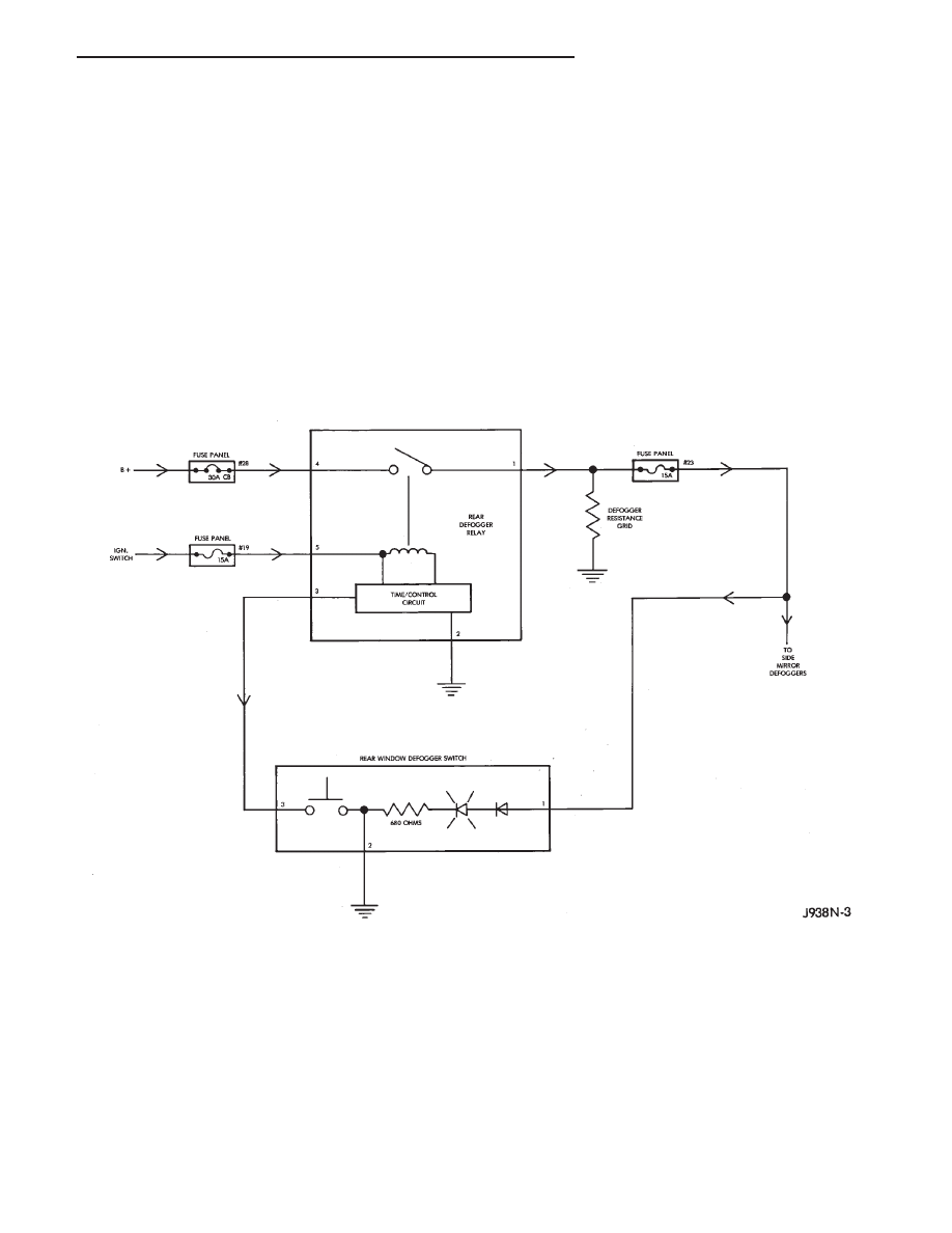
The power circuit to the grid is protected by the 30
amp Circuit Breaker #28 located in the fuse box.
Power for the relay is protected by the 15 amp #19
fuse located in the fuse box. There is another fuse,
#23, located in the fuse box that controls the power to
the switch and the side mirrors.
To defog the rear window, momentarily depress the
push button switch. An amber light above the push
button switch will illuminate indicating that the de-
fogger is operating.
If the ignition switch is ON the first activation of
the defog/defrost feature will last for 10 minutes.
Succeeding activations will last for 5 minutes unless
the ignition switch is turned OFF; then it will recycle
back to 10 minutes for the first activation.
To stop defogger operation, momentarily push the
switch a second time.
CAUTION: Use care when washing the inside of the
rear window to prevent damage to the defogger
heating elements. Use a soft cloth and a mild wash-
ing solution. Wiping motions should be parallel to
the heating elements. Also, keep all objects a safe
distance from the window to prevent damaging the
heating elements.
Z
REAR WINDOW DEFOGGER
8N - 1
DIAGNOSIS
Refer to Group 8W - Wiring Diagrams for a com-
plete circuit diagram.
REAR WINDOW DEFOGGER GRID TEST
It is possible, that a break may exist or occur in an
individual grid line resulting in no current flow
through the line. When a grid has an open circuit, the
area of glass normally cleared by that grid remains
fogged or iced unless, and/or until it is cleared by the
adjacent grids.
With the engine running, push the rear window
defogger switch to the ON position and release. The
pilot lamp above the push button switch should light,
indicating defogger operation.
Using a 12 volt DC voltmeter, contact the positive
lead to the feed side vertical bus element on the
inside surface of the glass. Contact the negative lead
to the ground side bus element. Meter should read
between 11 and 13 volts. Connect the negative lead of
the voltmeter to a good ground; the meter reading
should be constant.
Keep the negative lead connected to ground. Use
the positive lead and carefully contact each grid at
the approximate centerline of the window.
A voltage drop of one-half the full amount, approxi-
mately 6 volts, indicates a good grid or closed circuit.
A voltage drop of 12 volts at the centerline indicates
a break in the grid between the positive voltmeter
lead and the ground.
No voltage drop (0 volts) at the centerline indicates
a break in the grid between the centerline and the
voltage source or lead.
The exact location of the break can be pinpointed by
moving the positive voltmeter lead to the left or right
along the grid. An abrupt change in the voltage read-
ing will be noticed. The break is at that point in the
grid.
SWITCH TESTING
BATTERY, IGNITION & FUSES
• Check fuses #19, #23 and circuit breaker #28. Re-
place as required.
• If the fuses are not blown, check the battery side of
fuse #28 for battery voltage. If battery voltage is not
present replace the Maxi fuse located in the Power
Distribution Center.
• Check the ignition side of fuse #19, for battery
voltage. If battery voltage is not present check for an
open from the ignition switch.
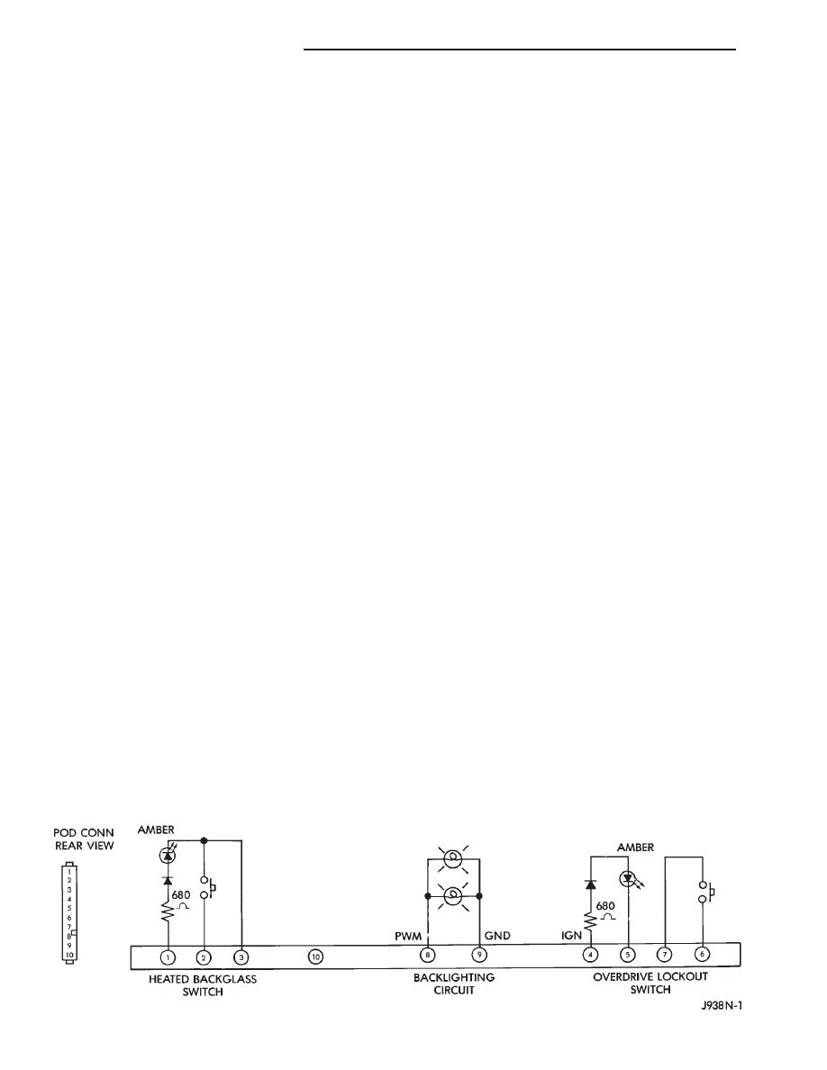
DEFOGGER SWITCH
Defogger switch connector separated from de-
fogger switch.
(1) Using a jumper wire, apply 12 volts to terminal
1 of switch.
(2) Using another jumper wire connect terminal 3
of switch to ground.
The indicator should light. If not replace switch. If
OK, proceed to next step.
(3) Remove jumper wires and connect an ohmmeter
to terminals 2 and 3 of switch.
(4) Push the switch. Ohmmeter should read less
than 1 ohm. If not replace switch. If OK, check for an
open circuit between:
• terminal 1 and fuse #23
• terminal 3 and ground
• terminal 2 and terminal 3 of the relay.
REAR DEFOGGER RELAY
Defogger relay connector separated from de-
fogger relay; turn ignition switch to RUN for
voltage tests; turn ignition switch to OFF for
resistance tests
• Measure voltage at relay connector terminal 5. The
meter should read battery voltage. If not, repair open
to fuse #19.
• Measure voltage at relay connector terminal 4. The
meter should read battery voltage. If not, repair open
to Circuit Breaker #28.
8N - 2
REAR WINDOW DEFOGGER
Z
• Measure resistance between relay connector termi-
nal 1 and Left Hand side (driver’s side) of defogger
grid. The meter should read zero ohms. If not, repair
open between relay connector and Left Hand side of
defogger grid.
• Measure resistance between relay connector termi-
nal 2 and a clean chassis ground. The meter should
read zero ohms. If not, repair open between relay
connector and ground.
• Connect relay connector and measure voltage at
terminal 3. The meter should read approximately 5
volts. If not, replace defogger relay.
DEFOGGER GRID
Turn defogger switch to ON; turn ignition
switch to RUN for voltage tests; turn ignition
switch to OFF for resistance tests
• Measure voltage at Right Hand side (passengers
side) of Defogger Grid. The meter should read battery
voltage. If not, repair open from defogger relay.
• Measure resistance for LH side of Defogger Grid to
a clean chassis ground. The meter should read zero
ohms. If not, repair open between RH side of Defogger
Grid and ground.
REAR WINDOW DEFOGGER SYSTEM SCHEMATIC
Z
REAR WINDOW DEFOGGER
8N - 3
SERVICE PROCEDURES
INDEX
page
page
Rear Defogger Relay
. . . . . . . . . . . . . . . . . . . . . . . 7
Rear Window Defogger Grid Repair
. . . . . . . . . . . . 4
Rear Window Defogger Switch Replacement
. . . . . 4
REAR WINDOW DEFOGGER GRID REPAIR
Locate the broken or open grid.
Use the grid repair kit (available as a service part)
by using the following procedure:
(1) Mark the location of the broken or open grid on
the exterior surface of the glass using a suitable
marking pencil.
(2) Lightly rub the area to be repaired (inside the rear
window) using fine steel wool. Clean the area with alco-
hol.
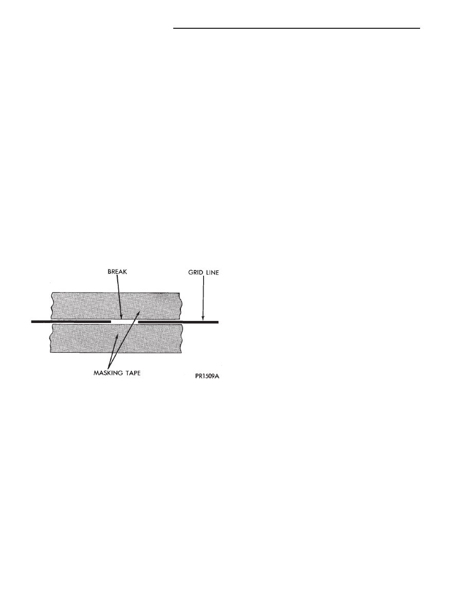
(3) Attach two strips of masking tape to the inside
surface of the rear window above and below the break
in the grid (Fig. 1).
(4) Remove package separator clamp and mix plas-
tic conductive epoxy thoroughly. Fold in half and cut
center corner to dispense epoxy.
(5) Apply conductive epoxy through slit in masking
tape. Overlap both ends of the break.
(6) For a terminal or pigtail replacement, mask
adjacent areas so epoxy can be extended onto line and
buss bar. Apply a thin layer of epoxy to area where
terminal was fastened and to adjacent line.
(7) Apply a thin layer of conductive epoxy on termi-
nal and place terminal on desired location. To prevent
terminal from moving while the epoxy is curing, it
must be wedged or clamped.
(8) Carefully remove masking tape from grid line.
(9) Allow epoxy to cure 24 hours at room tempera-
ture or use heat gun with a 260°-371°C (500°-700°F)
range for 15 minutes. Hold gun approximately
254mm (10 inches) from repaired area.
(10) After conductive epoxy is properly cured re-
move wedge from terminal and check out operation of
rear window defogger. Do not attach connectors until
curing is complete.
WARNING: REPAIR KIT MAY CAUSE SKIN OR EYE
IRRITATION.
CONTAINS EPOXY RESIN AND AMINE TYPE
HARDENER, HARMFUL IF SWALLOWED. AVOID
CONTACT WITH SKIN AND EYES. FOR SKIN, WASH
AFFECTED AREAS WITH SOAP AND WATER. DO
NOT TAKE INTERNALLY. IF TAKEN INTERNALLY,
INDUCE VOMITING; CALL A PHYSICIAN IMMEDI-
ATELY. IF IN CONTACT WITH EYES, FLUSH WITH
PLENTY OF WATER. USE WITH ADEQUATE VENTI-
LATION. DO NOT USE NEAR FIRE OR FLAME. CON-
TENTS CONTAIN 3% FLAMMABLE SOLVENTS.
WARNING: KEEP OUT OF REACH OF CHILDREN.
REAR WINDOW DEFOGGER SWITCH REPLACE-
MENT
(1) Disconnect negative cable from the battery.
(2) Remove ash tray.
(3) Remove 6 screws holding center cluster bezel
(Fig. 2).
(4) Remove center bezel.
(5) Remove 2 screws holding dash pad located be-
hind top of center bezel.
(6) Gently pry defroster grille out of dash pad.
(7) Unplug sensors (if equipped) and set defroster
grille aside.
(8) Remove 4 screws in defroster duct opening hold-
ing dash pad (Fig. 3).
(9) Remove 3 screws above Instrument Panel clus-
ter holding dash pad (Fig. 4).
(10) Open glove box and remove 2 screws holding
dash pad.
(11) Remove dash pad pulling up to unsnap end
clips.
(12) With driver’s door open remove 1 screw from
the side of the lower trim panel (Fig. 5).
(13) Remove 4 screws holding the steering column
cover (Fig. 6).
(14) Remove 1 screw from bottom of lower trim
panel and pull panel off. There is also a clip holding
the panel to the instrument panel.
Fig. 1 Grid Line Repair (Typical)
8N - 4
REAR WINDOW DEFOGGER
Z
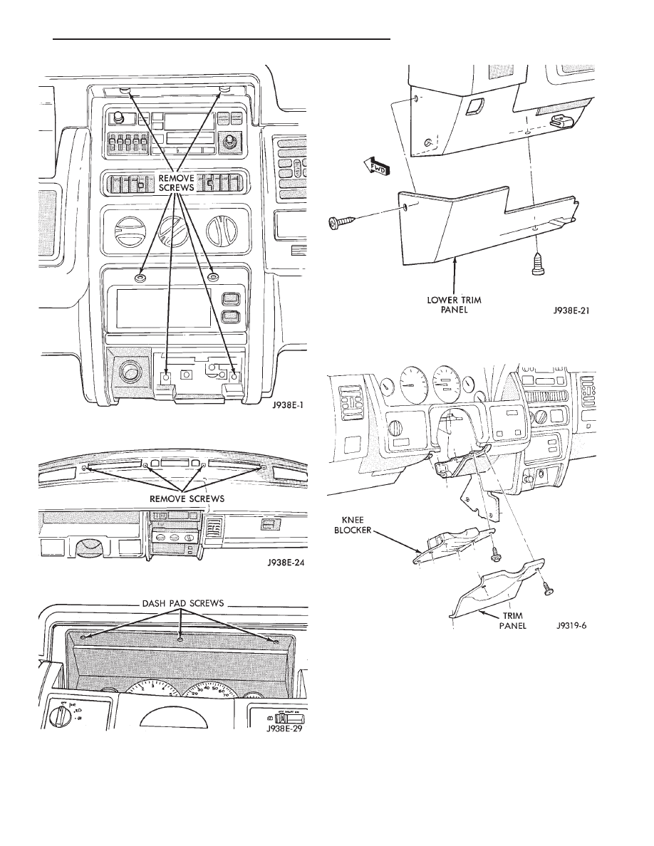
Fig. 2 Remove Center Bezel Screws
Fig. 3 Upper Dash Pad Attaching Screws
Fig. 4 Remove Screws Holding Dash Pad
Fig. 5 Lower Trim Panel
Fig. 6 Steering Column Cover And Knee Blocker
Z
REAR WINDOW DEFOGGER
8N - 5
(15) Remove 6 screws holding knee blocker.
(16) Remove steering column retaining nuts.
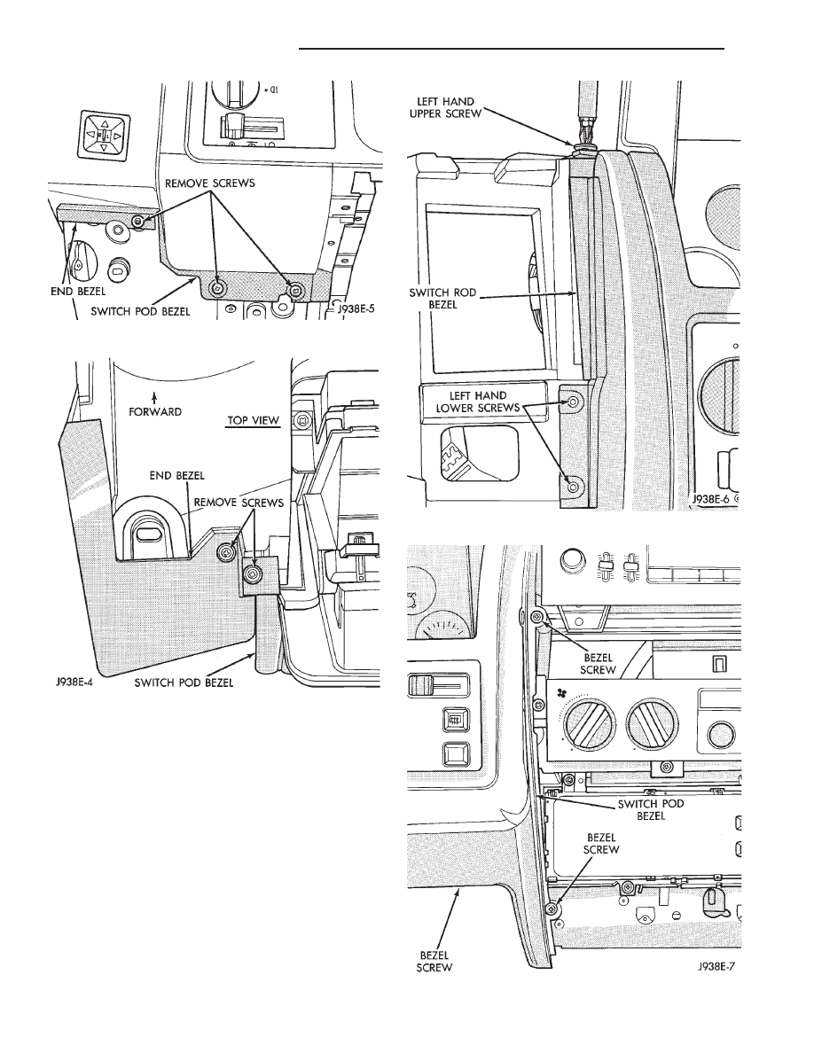
(17) Remove 3 screws holding bottom of bezels (Fig.
7).
(18) Remove 2 screws holding top of end and switch
pod bezels (Fig. 8). The end bezel can now be re-
moved.
(19) Remove 2 screws holding left side of switch
pod bezel (Fig. 9).
(20) Remove 3 screws holding right hand side of
switch pod bezel (Fig. 10).
Fig. 7 Remove Screws Holding Bottom Of Bezels
Fig. 8 Remove Screws Holding Top Of Bezels
Fig. 9 Left Hand Switch Pod Bezel Screws
Fig. 10 Right Hand Switch Pod Bezel Screws
8N - 6
REAR WINDOW DEFOGGER
Z
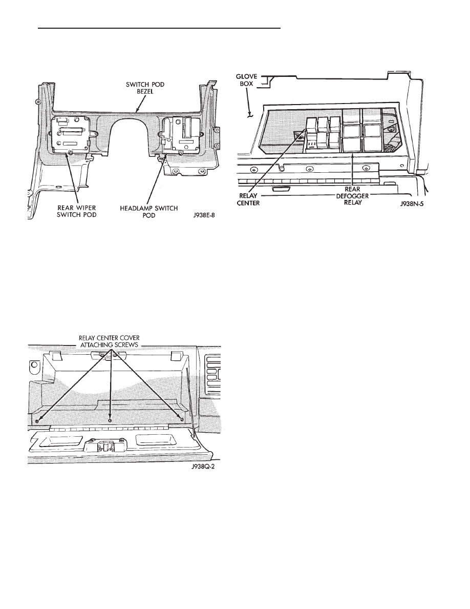
(21) Pull switch pod bezel out far enough to re-
move switch connectors. Disconnect connectors from
each switch pod and remove bezel (Fig. 11).
(22) Remove required switch pod attaching screws
and switch pod.
(23) Reverse the removal procedures to install a
new switch pod. Tighten steering column retaining
nuts to 105 in. lbs.
REAR DEFOGGER RELAY
(1) Open glove box and remove 3 screws holding
relay center cover (Fig. 12).
(2) Remove the RED relay from the relay center
(Fig. 13).
Fig. 11 Rear View of Switch Pod Bezel
Fig. 12 Relay Center Cover
Fig. 13 Rear Defogger Relay
Z
REAR WINDOW DEFOGGER
8N - 7

Document Outline
Wyszukiwarka
Podobne podstrony:
BMW E38 schematic Rear window defogger
93ZJ Secc 8S Power Windows
defogger rear window
Popular Mechanics Repairing Your Rear Window Defroster
93ZJ Secc 11 Exhaust System and Intake Manifold
93ZJ Secc 8J Turn Signals and Hazard Warning Flashes
93ZJ Secc 8F Audio Systems
93ZJ Secc 8R Power Seats
93ZJ Secc 16 Propeller Shafts
93ZJ Secc 6 Clutch
93ZJ Secc 8L Lamps
93ZJ Secc 8B Battery Starter Motor Generator Service
93ZJ Secc 8A Electrical Systems
93ZJ Secc 8M Restraint Systems
93ZJ Secc 22 Wheels and Tires
93ZJ Secc 25 Emission Control Systems
93ZJ Secc 0 Lubrication and Maintenance
93ZJ Secc 8G Horns
93ZJ Secc 8Q Vehicle Theft Security System
więcej podobnych podstron