
BRITISH STANDARD
BS EN ISO
1133:2005
Plastics —
Determination of the
melt mass-flow rate
(MFR) and the melt
volume-flow rate (MVR)
of thermoplastics
The European Standard EN ISO 1133:2005 has the status of a
British Standard
ICS 83.080.20
12&23<,1*:,7+287%6,3(50,66,21(;&(37$63(50,77('%<&23<5,*+7/$:
Licensed Copy: Institute Of Technology Tallaght, Institute of Technology, Tue Jun 27 14:09:31 BST 2006, Uncontrolled Copy, (c) BSI

BS EN ISO 1133:2005
This British Standard was
published under the authority
of the Standards Policy and
Strategy Committee
on 11 October 2005
© BSI 11 October 2005
ISBN 0 580 46474 1
National foreword
This British Standard is the official English language version of
EN ISO 1133:2005. It is identical with ISO 1133:2005. It supersedes
BS EN ISO 1133:2000 which is withdrawn.
The UK participation in its preparation was entrusted to Technical Committee
PRI/21, Testing of plastics, which has the responsibility to:
A list of organizations represented on this committee can be obtained on
request to its secretary.
Cross-references
The British Standards which implement international or European
publications referred to in this document may be found in the BSI Catalogue
under the section entitled “International Standards Correspondence Index”, or
by using the “Search” facility of the BSI Electronic Catalogue or of British
Standards Online.
This publication does not purport to include all the necessary provisions of a
contract. Users are responsible for its correct application.
Compliance with a British Standard does not of itself confer immunity
from legal obligations.
—
aid enquirers to understand the text;
—
present to the responsible international/European committee any
enquiries on the interpretation, or proposals for change, and keep UK
interests informed;
—
monitor related international and European developments and
promulgate them in the UK.
Summary of pages
This document comprises a front cover, an inside front cover, the EN ISO title
page, the EN ISO foreword page, the ISO title page, pages ii to iv, pages 1 to 16,
an inside back cover and a back cover.
The BSI copyright notice displayed in this document indicates when the
document was last issued.
Amendments issued since publication
Amd. No.
Date
Comments
Licensed Copy: Institute Of Technology Tallaght, Institute of Technology, Tue Jun 27 14:09:31 BST 2006, Uncontrolled Copy, (c) BSI

www.bzfxw.com
EUROPEAN STANDARD
NORME EUROPÉENNE
EUROPÄISCHE NORM
EN ISO 1133
June
2005
ICS 83.080.20
Supersedes EN ISO 1133:1999
English version
Plastics - Determination of the melt mass-flow rate (MFR) and
the melt volume-flow rate (MVR) of thermoplastics (ISO
1133:2005)
Plastiques - Détermination de l'indice de fluidité à chaud
des thermoplastiques, en masse (MFR) et en volume
(MVR) (ISO 1133:2005)
Kunststoffe - Bestimmung der Schmelze-Massefließrate
(MFR) und der Schmelze-Volumenfließrate (MVR) von
Thermoplasten (ISO 1133:2005)
This European Standard was approved by CEN on 19 May 2005.
CEN members are bound to comply with the CEN/CENELEC Internal Regulations which stipulate the conditions for giving this European
Standard the status of a national standard without any alteration. Up-to-date lists and bibliographical references concerning such national
standards may be obtained on application to the Central Secretariat or to any CEN member.
This European Standard exists in three official versions (English, French, German). A version in any other language made by translation
under the responsibility of a CEN member into its own language and notified to the Central Secretariat has the same status as the official
versions.
CEN members are the national standards bodies of Austria, Belgium, Cyprus, Czech Republic, Denmark, Estonia, Finland, France,
Germany, Greece, Hungary, Iceland, Ireland, Italy, Latvia, Lithuania, Luxembourg, Malta, Netherlands, Norway, Poland, Portugal, Slovakia,
Slovenia, Spain, Sweden, Switzerland and United Kingdom.
EUROPEAN COMMITTEE FOR STANDARDIZATION
C O M I T É E U R O P É E N D E N O R M A L I S A T I O N
E U R O P Ä I S C H E S K O M I T E E FÜ R N O R M U N G
Management Centre: rue de Stassart, 36 B-1050 Brussels
© 2005 CEN
All rights of exploitation in any form and by any means reserved
worldwide for CEN national Members.
Ref. No. EN ISO 1133:2005: E
Licensed Copy: Institute Of Technology Tallaght, Institute of Technology, Tue Jun 27 14:09:31 BST 2006, Uncontrolled Copy, (c) BSI

www.bzfxw.com
Foreword
This document (EN ISO 1133:2005) has been prepared by Technical Committee ISO/TC 61
"Plastics" in collaboration with Technical Committee CEN/TC 249 "Plastics", the secretariat of
which is held by IBN.
This European Standard shall be given the status of a national standard, either by publication of
an identical text or by endorsement, at the latest by December 2005, and conflicting national
standards shall be withdrawn at the latest by December 2005.
This document supersedes EN ISO 1133:1999.
According to the CEN/CENELEC Internal Regulations, the national standards organizations of
the following countries are bound to implement this European Standard: Austria, Belgium,
Cyprus, Czech Republic, Denmark, Estonia, Finland, France, Germany, Greece, Hungary,
Iceland, Ireland, Italy, Latvia, Lithuania, Luxembourg, Malta, Netherlands, Norway, Poland,
Portugal, Slovakia, Slovenia, Spain, Sweden, Switzerland and United Kingdom.
Endorsement notice
The text of ISO 1133:2005 has been approved by CEN as EN ISO 1133:2005 without any
modifications.
EN ISO 1133:2005
Licensed Copy: Institute Of Technology Tallaght, Institute of Technology, Tue Jun 27 14:09:31 BST 2006, Uncontrolled Copy, (c) BSI

www.bzfxw.com
Reference number
ISO 1133:2005(E)
INTERNATIONAL
STANDARD
ISO
1133
Fourth edition
2005-06-01
Plastics — Determination of the melt
mass-flow rate (MFR) and the melt
volume-flow rate (MVR) of thermoplastics
Plastiques — Détermination de l'indice de fluidité à chaud des
thermoplastiques, en masse (MFR) et en volume (MVR)
EN ISO 1133:2005
Licensed Copy: Institute Of Technology Tallaght, Institute of Technology, Tue Jun 27 14:09:31 BST 2006, Uncontrolled Copy, (c) BSI

www.bzfxw.com
ii
Licensed Copy: Institute Of Technology Tallaght, Institute of Technology, Tue Jun 27 14:09:31 BST 2006, Uncontrolled Copy, (c) BSI

www.bzfxw.com
iii
Contents
Page
Foreword............................................................................................................................................................ iv
1 Scope ..................................................................................................................................................... 1
2 Normative
references ........................................................................................................................... 1
3 Terms
and
definitions........................................................................................................................... 2
4 Principle................................................................................................................................................. 3
5 Apparatus .............................................................................................................................................. 3
5.1 Extrusion
plastometer .......................................................................................................................... 3
5.2 Accessory
equipment........................................................................................................................... 6
6 Test
sample ........................................................................................................................................... 7
6.1 Sample
form .......................................................................................................................................... 7
6.2 Conditioning.......................................................................................................................................... 7
7
Temperature-calibration, cleaning and maintenance of the apparatus .......................................... 7
7.1
Calibration of the temperature-control system ................................................................................. 7
7.2 Cleaning
the
apparatus ........................................................................................................................ 8
8 Procedure
A:
mass-measurement
method ........................................................................................ 8
8.1
Selection of temperature and load...................................................................................................... 8
8.2 Cleaning ................................................................................................................................................. 8
8.3
Selection of sample mass and charging cylinder ............................................................................. 8
8.4 Measurements....................................................................................................................................... 9
8.5 Expression
of
results ......................................................................................................................... 10
9 Procedure
B:
displacement-measurement
method ........................................................................ 10
9.1
Selection of temperature and load.................................................................................................... 10
9.2
Minimum piston displacement distance........................................................................................... 10
9.3 Timer .................................................................................................................................................... 11
9.4
Preparation for the test ...................................................................................................................... 11
9.5 Measurements..................................................................................................................................... 11
9.6 Expression
of
results ......................................................................................................................... 11
10 Flow
rate
ratio
(FRR)........................................................................................................................... 12
11 Precision .............................................................................................................................................. 12
12 Test
report ........................................................................................................................................... 13
Annex A (normative) Test conditions for MFR and MVR determinations .................................................. 14
Annex B (informative) Conditions specified in International Standards for the determination of the
melt flow rate of thermoplastic materials......................................................................................... 15
EN ISO 1133:2005
Licensed Copy: Institute Of Technology Tallaght, Institute of Technology, Tue Jun 27 14:09:31 BST 2006, Uncontrolled Copy, (c) BSI

www.bzfxw.com
iv
Foreword
ISO (the International Organization for Standardization) is a worldwide federation of national standards bodies
(ISO member bodies). The work of preparing International Standards is normally carried out through ISO
technical committees. Each member body interested in a subject for which a technical committee has been
established has the right to be represented on that committee. International organizations, governmental and
non-governmental, in liaison with ISO, also take part in the work. ISO collaborates closely with the
International Electrotechnical Commission (IEC) on all matters of electrotechnical standardization.
International Standards are drafted in accordance with the rules given in the ISO/IEC Directives, Part 2.
The main task of technical committees is to prepare International Standards. Draft International Standards
adopted by the technical committees are circulated to the member bodies for voting. Publication as an
International Standard requires approval by at least 75 % of the member bodies casting a vote.
Attention is drawn to the possibility that some of the elements of this document may be the subject of patent
rights. ISO shall not be held responsible for identifying any or all such patent rights.
ISO 1133 was prepared by Technical Committee ISO/TC 61, Plastics, Subcommittee SC 5, Physical-chemical
properties.
This fourth edition cancels and replaces the third edition (ISO 1133:1997), in which the clauses relating to
temperature control have been revised. In addition, the clarity of the text has been improved.
EN ISO 1133:2005
Licensed Copy: Institute Of Technology Tallaght, Institute of Technology, Tue Jun 27 14:09:31 BST 2006, Uncontrolled Copy, (c) BSI

www.bzfxw.com
1
Plastics — Determination of the melt mass-flow rate (MFR) and
the melt volume-flow rate (MVR) of thermoplastics
1 Scope
This International Standard specifies two procedures for the determination of the melt mass-flow rate (MFR)
and the melt volume-flow rate (MVR) of thermoplastic materials under specified conditions of temperature and
load. Procedure A is a mass-measurement method. Procedure B is a displacement-measurement method.
Normally, the test conditions for measurement of melt flow rate are specified in the material standard with a
reference to this International Standard. The test conditions normally used for thermoplastics are listed in
Annexes A and B.
The MVR will be found particularly useful when comparing materials of different filler content and when
comparing filled with unfilled thermoplastics. The MFR can be determined from MVR measurements provided
the melt density at the test temperature and pressure is known.
These methods are in principle also applicable to thermoplastics for which the rheological behaviour is
affected during the measurement by phenomena such as hydrolysis, condensation or crosslinking, but only if
the effect is limited in extent and only if the repeatability and reproducibility are within an acceptable range.
For materials which show significantly affected rheological behaviour during testing, these methods are not
appropriate. In such cases, the use of the viscosity number in dilute solution, determined in accordance with
the relevant part of ISO 1628, is recommended for characterization purposes.
NOTE
The rates of shear in these methods are much smaller than those used under normal conditions of processing,
and therefore data obtained by these methods for various thermoplastics may not always correlate with their behaviour
during processing. Both methods are used primarily in quality control.
2 Normative
references
The following referenced documents are indispensable for the application of this document. For dated
references, only the edition cited applies. For undated references, the latest edition of the referenced
document (including any amendments) applies.
ISO 1622-2, Plastics — Polystyrene (PS) moulding and extrusion materials — Part 2: Preparation of test
specimens and determination of properties
ISO 1628 (all parts), Plastics — Determination of the viscosity of polymers in dilute solution using capillary
viscometers
ISO 1872-2, Plastics — Polyethylene (PE) moulding and extrusion materials — Part 2: Preparation of test
specimens and determination of properties
ISO 1873-2, Plastics — Polypropylene (PP) moulding and extrusion materials — Part 2: Preparation of test
specimens and determination of properties
ISO 2580-2, Plastics — Acrylonitrile-butadiene-styrene (ABS) moulding and extrusion materials — Part 2:
Preparation of test specimens and determination of properties
EN ISO 1133:2005
Licensed Copy: Institute Of Technology Tallaght, Institute of Technology, Tue Jun 27 14:09:31 BST 2006, Uncontrolled Copy, (c) BSI

www.bzfxw.com
2
ISO 2897-2, Plastics — Impact-resistant polystyrene (PS-I) moulding and extrusion materials — Part 2:
Preparation of test specimens and determination of properties
ISO 4287, Geometrical Product Specifications (GPS) — Surface texture: Profile method — Terms, definitions
and surface texture parameters
ISO 4613-2, Plastics — Ethylene/vinyl acetate (E/VAC) moulding and extrusion materials — Part 2:
Preparation of test specimens and determination of properties
ISO 4894-2, Plastics — Styrene/acrylonitrile (SAN) moulding and extrusion materials — Part 2: Preparation of
test specimens and determination of properties
ISO 6402-2, Plastics — Acrylonitrile-styrene-acrylate (ASA), acrylonitrile-(ethylene-propylene-diene)-styrene
(AEPDS) and acrylonitrile-(chlorinated polyethylene)-styrene (ACS) moulding and extrusion materials —
Part 2: Preparation of test specimens and determination of properties
ISO 6507-1, Metallic materials — Vickers hardness test — Part 1: Test method
ISO 7391-2, Plastics — Polycarbonate (PC) moulding and extrusion materials — Part 2: Preparation of test
specimens and determination of properties
ISO 8257-2, Plastics — Poly(methyl methacrylate) (PMMA) moulding and extrusion materials — Part 2:
Preparation of test specimens and determination of properties
ISO 8986-2, Plastics — Polybutene (PB) moulding and extrusion materials — Part 2: Preparation of test
specimens and determination of properties
ISO 9988-2, Plastics — Polyoxymethylene (POM) moulding and extrusion materials — Part 2: Preparation of
test specimens and determination of properties
ISO 10366-2, Plastics — Methyl methacrylate-acrylonitrile-butadiene-styrene (MABS) moulding and extrusion
materials — Part 2: Preparation of test specimens and determination of properties
ISO 15494, Plastic piping systems for industrial applications — Polybutene (PB), polyethylene (PE) and
polypropylene (PP) — Specifications for components and the system — Metric series
ISO 15876-3, Plastics piping systems for hot and cold water installations — Polybutylene (PB) — Part 3:
Fittings
3 Terms and definitions
For the purpose of this document, the following terms and definitions apply.
3.1
melt mass-flow rate
MFR
rate of extrusion of a molten resin through a die of specified length and diameter under prescribed conditions
of temperature, load and piston position in the barrel of an extrusion plastometer, the rate being determined as
the mass extruded over a specified time
NOTE
The correct SI units are decigrams per minute (dg/min). However, grams per 10 minutes (g/10 min) have
customarily been used in the past and are also acceptable.
EN ISO 1133:2005
Licensed Copy: Institute Of Technology Tallaght, Institute of Technology, Tue Jun 27 14:09:31 BST 2006, Uncontrolled Copy, (c) BSI

www.bzfxw.com
3
3.2
melt volume-flow rate
MVR
rate of extrusion of a molten resin through a die of specified length and diameter under prescribed conditions
of temperature, load and piston position in the barrel of an extrusion plastometer, the rate being determined as
the volume extruded over a specified time
NOTE
The correct SI units are cubic decimetres per minute (dm
3
/min). More commonly used units, which are also
acceptable, are cubic centimetres per 10 minutes (cm
3
/10 min).
3.3
load
combined mass of piston and added weight, as specified by the conditions of the test
NOTE
It is expressed in kilograms (kg).
4 Principle
The melt mass-flow rate (MFR) and the melt volume-flow rate (MVR) are determined by extruding molten
material from the barrel of a plastometer under preset conditions of temperature and load. For melt mass-flow
rate, timed segments of the extrudate are weighed and the extrudate rate is calculated in g/10 min and
recorded. For melt volume-flow rate, the distance that the piston moves in a specified time or the time required
for the piston to move a specified distance is measured to generate data in cm
3
/10 min. Melt volume-flow rate
may be converted to melt mass-flow rate, or vice-versa, if the density of the material is known under the
conditions of the test.
5 Apparatus
5.1 Extrusion
plastometer
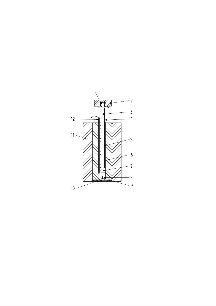
The basic apparatus comprises an extrusion plastometer operating at a fixed temperature. The general design
is as shown in Figure 1. The thermoplastic material, which is contained in a vertical cylinder, is extruded
through a die by a piston loaded with a known weight. The apparatus consists of the following essential parts.
5.1.1 Cylinder, fixed in a vertical position (see 5.1.5). The cylinder shall be manufactured from a material
resistant to wear and corrosion up to the maximum temperature of the heating system, and the finish,
properties and dimensions of its surface shall not be affected by the material being tested. For particular
materials, measurements may be required at temperatures up to 450 °C. The cylinder shall have a length
between 115 mm and 180 mm and an internal diameter of 9,550 mm r 0,025 mm. The base of the cylinder
shall be thermally insulated in such a way that the area of exposed metal is less than 4 cm
2
, and it is
recommended that an insulating material such as Al
2
O
3
, ceramic fibre or another suitable material be used in
order to avoid sticking of the extrudate.
The bore shall be hardened to a Vickers hardness of no less than 500 (HV 5 to HV 100) (see ISO 6507-1) and
shall be manufactured by a technique that produces a surface roughness of less than Ra (arithmetical mean
deviation) = 0,25 µm (see ISO 4287). If necessary, a piston guide shall be provided to keep friction caused by
misalignment of the piston down to a minimum.
NOTE
Excessive wear of the cylinder, piston head, and piston is an indication of misalignment of the piston. Regular
checking for wear and change to the surface appearance of the cylinder, piston and piston head is required to ensure
these items are within specification.
5.1.2 Piston, having a working length at least as long as the cylinder. The piston shall be manufactured
from a material resistant to wear and corrosion up to the maximum temperature of the heating system and its
properties and dimensions shall not be affected by the material being tested. The piston shall have a head
6,35 mm r 0,10 mm in length. The diameter of the head shall be less than the internal diameter of the cylinder
by 0,075 mm r 0,010 mm. The upper edge shall have its sharp edge removed. Above the head, the piston
EN ISO 1133:2005
Licensed Copy: Institute Of Technology Tallaght, Institute of Technology, Tue Jun 27 14:09:31 BST 2006, Uncontrolled Copy, (c) BSI
www.bzfxw.com
4
shall be relieved to
u 9 mm diameter. A stud may be added at the top of the piston to support a removable
weight, but the piston shall be thermally insulated from the weight. Along the piston stem, two thin annular
reference marks shall be scribed 30 mm apart and so positioned that the upper one is aligned with the top of
the cylinder when the distance between the lower edge of the piston head and the top of the die is 20 mm.
These annular marks on the piston are used as reference points during the measurements (see 8.4 and 9.5).
To ensure satisfactory operation of the apparatus, the cylinder and the piston head shall be made of materials
of different hardness. It is convenient for ease of maintenance and renewal to make the cylinder of the harder
material.
The piston may be either hollow or solid. In tests with very low loads, the piston may need to be hollow,
otherwise it may not be possible to obtain the lowest prescribed load. When the test is performed with the
higher loads, a solid piston or hollow piston with guides shall be used.
Key
1 insulation
2 removable
weight
3 piston
4 upper reference mark
5 lower
reference
mark
6 cylinder
7 piston
head
8 die
9 die retaining plate
10 insulating plate
11 insulation
12 temperature sensor
Figure 1 — Typical apparatus for determining melt flow rate, showing one possible configuration
5.1.3 Temperature-control
system: For all cylinder temperatures that can be set, the temperature control
shall be such that, between 10 mm above the top of the die and 75 mm above the top of the die, the
temperature differences measured do not exceed those given in Table 1 throughout the duration of the test.
NOTE
The temperature may be measured with thermocouples, platinum-resistance sensors, or mercury-in-glass
thermometers embedded in the wall. If the apparatus is equipped in this way, the temperature may not be exactly the
same as that in the melt, but the temperature-control system may be calibrated (see 7.1) to read in melt temperature.
The temperature-control system shall allow the test temperature to be set in steps of 0,2 °C or less.
EN ISO 1133:2005
Licensed Copy: Institute Of Technology Tallaght, Institute of Technology, Tue Jun 27 14:09:31 BST 2006, Uncontrolled Copy, (c) BSI

www.bzfxw.com
5
Table 1 — Maximum allowable variation in temperature with distance
and with time throughout the test
Maximum variation in test temperature
a
Test temperature, T
qC
with distance at between
10 mm and 75 mm above
the die surface
°C
with time at 10 mm above
the die surface
b
°C
125
u T 250
r 2,0
r 0,5
c
250
u T 300
r 2,5
r 0,5
300
u T
r 3,0
r 1,0
a
Variation is over the normal time of a test, typically less than 25 min, and can be verified during
calibration of the equipment.
b
When using a 4 mm length die (see 5.1.4), the readings should be made 14 mm above the die
surface.
c
A value of 0,2 °C is preferred since it gives better reproducibility. It is intended that the value of
0,2 °C will become a requirement at the next revision of this International Standard.
5.1.4 Die, made of tungsten carbide or hardened steel, 8,000 mm r 0,025 mm in length. The interior of the
bore shall be manufactured circular, straight and uniform in diameter such that in all positions it is within
r 0,005 mm of a true cylinder of nominal diameter 2,095 mm. The bore diameter shall be checked regularly
with a go/no-go gauge. If outside the tolerance limits, the die shall be discarded. The die shall have ends that
are flat, perpendicular to the axis of the bore and free from visible machining marks.
If testing materials with a melt mass-flow rate ! 75 g/10 min or a melt volume-flow rate ! 75 cm
3
/10 min, a
half-height, half-diameter die 4,000 mm r 0,025 mm in length and with a bore of nominal diameter
1,050 mm r 0,005 mm should preferably be used. No spacer shall be used with this die to increase the
apparent length to 8,00 mm.
For testing potentially corrosive materials, dies made of cobalt-chromium-tungsten alloy, chromalloy, synthetic
sapphire or other suitable materials may be used.
The bore shall be hardened to a Vickers hardness of no less than 500 (HV 5 to HV 100) (see ISO 6507-1) and
shall be manufactured by a technique that produces a surface roughness of less than Ra (arithmetical mean
deviation) = 0,25 µm (see ISO 4287). The die shall not project beyond the base of the cylinder (see Figure 1)
and shall be mounted so that its bore is co-axial with the cylinder bore.
The flat surfaces of the die shall be checked to ensure that the area around the bore is not chipped. Any
chipping will cause errors and chipped dies shall be discarded.
5.1.5 Means of setting and maintaining the cylinder truly vertical: A two-directional bubble level, set
normal to the cylinder axis, and adjustable supports for the apparatus are suitable for the purpose.
NOTE
This is to avoid excessive friction caused by the piston leaning to one side or bending under heavy loads. A
dummy piston with a spirit level on its upper end is also a suitable means of checking conformity with this requirement.
5.1.6 Load: A set of removable weights, which may be adjusted so that the combined mass of the weights
and the piston gives the selected nominal load to an accuracy of r 0,5 %, are mounted on top of the piston.
Alternatively, a mechanical loading device combined with, for example, a load cell, providing the same level of
accuracy as the removable weights, may be used.
EN ISO 1133:2005
Licensed Copy: Institute Of Technology Tallaght, Institute of Technology, Tue Jun 27 14:09:31 BST 2006, Uncontrolled Copy, (c) BSI

www.bzfxw.com
6
5.2 Accessory
equipment
5.2.1 General
5.2.1.1 Packing rod, made of non-abrasive material, for introducing test samples into the cylinder.
5.2.1.2 Cleaning equipment (see 7.2).
5.2.1.3 Go/no-go gauge, one end having a pin with a diameter equal to that of the die bore minus the
allowed tolerance (go gauge) and the opposite end having a pin with a diameter equal to that of the die bore
plus the allowed tolerance (no-go gauge). The pin gauge shall be sufficiently long to check the full length of
the die using the go gauge.
5.2.1.4 Temperature-calibration device (mercury-in-glass thermometer, thermocouple, platinum-resistance
sensor or other temperature-measuring device). The temperature sensor shall have a temperature readout
resolution of 0,1 °C or better. Calibrate the temperature-indicating device using for example a light-gauge
probe-type thermocouple or a platinum-resistance sensor having a short sensing length. The thermocouple
should be encased in a metallic sheath having a diameter of approximately 1,6 mm with its hot junction
grounded to the end of the sheath.
5.2.1.5 Die plug: A device shaped at one end so that it effectively blocks the die exit and prevents drool of
molten material while allowing rapid removal prior to initiation of the test, e.g. a plug attached to a compressed
spring.
5.2.1.6 Piston/weight support, of sufficient length to hold the piston so that the lower reference mark is
25 mm above the top of the cylinder.
5.2.2 Equipment for procedure A (see Clause 8)
5.2.2.1 Cutting tool, for cutting off extruded sample. A sharp-edged spatula has been found suitable.
5.2.2.2 Timer, accurate to r 0,1 s for melt mass-flow rates
u 100 g/10 min and to r 0,01 s for melt mass-flow
rates ! 100 g/10 min. Compare with a calibrated timing device over a period of 15 min to 20 min and ensure
that the tolerance is within r 0,07 % of the total time measured.
NOTE
Procedure A is not recommended for measurement of melt mass-flow rates ! 100 g/10 min unless using a
half-height, half-diameter die.
5.2.2.3 Balance, accurate to r 0,5 mg.
5.2.3 Equipment for procedure B (see Clause 9)
5.2.3.1 Measurement
equipment, for the automatic measurement of distance and time for the piston
movement, using single or multiple determinations for a single charge (see Table 2).
Table 2 — Piston distance and time measurement accuracy requirements
MFR (g/10 min) or MVR (cm
3
/10 min)
a
Distance (mm)
Time (s)
0,1 to 1,0
r 0,02
r 0,1
! 1,0 to 100
r 0,1
r 0,1
! 100
r 0,1
r 0,01
a
For multiple measurements in a single charge regardless of the MFR or MVR of the material, the requirements are the same as for
MFR or MVR ! 100.
EN ISO 1133:2005
Licensed Copy: Institute Of Technology Tallaght, Institute of Technology, Tue Jun 27 14:09:31 BST 2006, Uncontrolled Copy, (c) BSI

www.bzfxw.com
7
6 Test
sample
6.1 Sample
form
The test sample may be in any form that can be introduced into the bore of the cylinder, for example granules,
strips of film, powder or sections of moulded or extruded parts. The test sample may fill the cylinder bore to a
height of 75 mm prior to starting the test.
NOTE 1
In order to ensure void-free extrudates when testing powders, it may be necessary to first compress the
material to a preform or pellets.
NOTE 2
The form of the test sample can be a significant factor in determining the reproducibility. The form of the test
sample should therefore be controlled to improve the comparability of inter-laboratory results and to reduce the variability
between runs.
6.2 Conditioning
The test sample shall be conditioned and, if considered necessary, stabilized prior to testing, in accordance
with the appropriate material specification standard.
7 Temperature-calibration, cleaning and maintenance of the apparatus
7.1 Calibration of the temperature-control system
7.1.1 Calibration
procedure
It is necessary to verify regularly the accuracy of the temperature-control system (5.1.3).
Set the temperature-control system to the required temperature (as indicated by the control temperature-
indicating device). Charge the cylinder with a quantity of the material to be tested, or a material representative
thereof (see 7.1.2), using the same technique as for a test (see 8.3). Five minutes after completing the
charging of the material, introduce the calibrated temperature-indicating device (5.2.1.4) into the sample
chamber and immerse it in the material therein until the sensor is 10 mm from the upper face of the die. After
a further interval of not less than 4 min and not more than 10 min, correct the temperature indicated by the
control temperature-indicating device by algebraic addition of the difference between the temperatures read
on the two temperature sensors. It is also necessary to verify the temperature profile along the cylinder. For
this, measure the temperature of the material also at 30 mm, 50 mm and 75 mm above the upper face of the
die. Check the temperature over time as well as distance for conformance to Table 1. If using a calibration
thermometer as the temperature-indicating device, preheat the thermometer to the same temperature as that
being measured.
NOTE
It is recommended that, in verifying the temperature profile along the cylinder, the measurements are started
at the highest point above the die.
An alternative technique for calibration is to use a sheathed thermocouple or platinum-resistance temperature
sensor with tip diameter of 9,4 mm r 0,1 mm for insertion in the bore without material present. Another
technique is use of a piston provided with thermocouples at heights of 10 mm, 30 mm, 50 mm and 75 mm
above the die, which can be inserted completely in the bore and fits the bore closely. This configuration will
allow temperature calibration of the apparatus and verification of the temperature profile at the same time.
7.1.2 Calibration
material
It is essential that the material used during calibration be sufficiently fluid to permit, for instance, a mercury-
filled thermometer bulb to be introduced without excessive force or risk of damage. A stable material with an
MFR of greater than 45 g/10 min (2,16 kg load) at the calibration temperature has been found suitable.
EN ISO 1133:2005
Licensed Copy: Institute Of Technology Tallaght, Institute of Technology, Tue Jun 27 14:09:31 BST 2006, Uncontrolled Copy, (c) BSI

www.bzfxw.com
8
If such a material is used for calibration purposes in place of a more viscous material which is to be tested, the
dummy material shall have a thermal diffusivity similar to that of the material to be tested, so that warm-up
behaviour is similar. It is necessary that the quantity charged for calibration be such that, when the calibration
temperature sensor is subsequently introduced, the appropriate length of the sensor stem is immersed for
accurate temperature measurement. This can be checked by inspecting the upper edge of the material
coating the end of the calibration temperature sensor, removing the sensor from the cylinder if necessary.
7.2 Cleaning
the
apparatus
WARNING — The operating conditions may entail partial decomposition of the material under test or
any material used to clean the instrument, or cause them to release dangerous volatile substances, as
well as presenting the risk of burns. The user of this International Standard is therefore responsible
for keeping him- or herself informed of possible risks of accident and for providing appropriate means
of protection.
The apparatus shall be cleaned thoroughly after each determination. The cylinder may be cleaned with cloth
patches. The piston shall be cleaned while hot with a cotton cloth. The die may be cleaned with a closely
fitting brass reamer, high-speed drill bit of 2,08 mm diameter, or wooden peg. Pyrolytic cleaning of the die in a
nitrogen atmosphere at about 550 °C may also be used. Abrasives or materials likely to damage the surface
of the piston, cylinder or die shall not be used. Take care that the cleaning procedure used does not affect the
cylinder and die dimensions or surface finish. The die bore shall be checked with a go/no-go gauge after
cleaning. When testing polyolefins, do not use copper-containing materials, e.g. brass brushes, to clean the
cylinder, piston or die as this may accelerate degradation of the polymer.
If solvents are used to clean the cylinder, take care that any effect they may have on the next determination is
negligible.
8 Procedure A: mass-measurement method
8.1 Selection
of
temperature and load
Refer to Annexes A and B. Use the conditions in Table B.1 if the material is listed there. The material standard
takes precedence over this International Standard. If no material standard exists, use an appropriate set of
conditions from Table A.1 based on knowledge of the melting point of the material or the processing
conditions recommended by manufacturer.
8.2
Cleaning
Clean the apparatus (see 7.2). Before beginning a series of tests, ensure that the cylinder and piston have
been at the selected temperature for not less than 15 min.
8.3
Selection of sample mass and charging cylinder
Charge the cylinder with 3 g to 8 g of the sample according to the anticipated MFR or MVR (see Table 3).
During the charging, compress the material with the packing rod (5.2.1.1), using hand pressure. For materials
susceptible to oxidative degradation, ensure the charge is as free from air as possible. Complete the charging
process in 1 min. The preheat time of 5 min begins after charging of the cylinder has been completed.
NOTE
Variations in the packing pressure used to compress the material in the cylinder can cause poor repeatability
of results. Use of the same mass of sample for the analysis of materials of similar MFR or MVR will reduce variability in
the data.
Immediately put the piston in the cylinder. The piston may be either unloaded or preloaded with the test weight
or, for materials with high flow rates, a smaller weight. If the melt mass-flow rate or melt-volume flow rate of
the material is high, that is, more than 10 g/10 min or 10 cm
3
/10 min, the loss of sample during preheating will
be appreciable. In this case, use an unloaded piston or one carrying a smaller load during the preheating
period, and then change to the desired load at the end of the 5 min preheating time. In the case of very high
EN ISO 1133:2005
Licensed Copy: Institute Of Technology Tallaght, Institute of Technology, Tue Jun 27 14:09:31 BST 2006, Uncontrolled Copy, (c) BSI

www.bzfxw.com
9
melt flow rates, a weight support should preferably be used and a die plug may be necessary. If the die plug is
used and less than the desired load is on the piston, add the desired load and allow the material to stabilize
for a few seconds before removing the die plug. If a weight support and die plug are both used, remove the
weight support first.
NOTE
To minimize the risk of burns from hot material coming out of the die rapidly, it is recommended that heat-
resistant gloves be worn during the removal of the die plug.
Table 3 — Guidelines for experimental parameters
MFR (g/10min) or MVR (cm
3
/10min)
a
Mass of test sample in cylinder
b, c
g
Extrudate cut-off time-interval
s
W 0,1 but u 0,5
3 to 5
240
! 0,5 but
u 1
4 to 6
120
! 1 but
u 3,5
4 to 6
60
! 3,5 but
u 10
4 to 8
30
! 10
4 to 8
5 to 15
d
a
It is recommended that a melt flow rate should not be measured if the value obtained in this test is less than 0,1 g/10 min (MFR) or
0,1 cm
3
/10 min (MVR). Melt mass-flow rates greater than 100 g/10 min should only be measured if the timer resolution is 0,01 s and
procedure B is used when a standard 8,00 mm die is used. Alternatively, the half-height, half-diameter die may be used with
procedure A (see 5.1.4).
b
When the density of the material is greater than 1,0 g/cm
3
, it may be necessary to increase the mass of the test sample. Use the
low mass values for low-density materials.
c
Sample mass is a significant factor in determining the repeatability of this test and may need to be controlled to 0,1 g to reduce
variability between runs.
d
To achieve adequate repeatability when testing materials having an MFR greater than 25 g/10 min (or MVR greater than
25 cm
3
/10 min), it may be necessary either to control and measure cut-off intervals to an accuracy of less than 0,1 s or to use
procedure B.
8.4 Measurements
8.4.1 Five minutes after completing the introduction of the test sample, place the selected weight on the
piston, if it was unloaded or under-loaded. During this time, check that the temperature has returned to that
selected. Allow the piston to descend under gravity until a bubble-free filament is extruded; this may be done
before or after loading, depending on the actual viscosity of the material. It is strongly recommended that
forced purging of the sample, done either manually or by using extra weights, before commencement of the
test be avoided. If any forced purging is required (i.e. to complete the procedure within the specified time limit),
it shall be finished at least 2 min before the start of the test. Any purging shall be carried out within a period of
1 min. Cut off the extrudate with the cutting tool (5.2.2.1), and discard. Continue to allow the loaded piston to
descend under gravity. When the lower reference mark has reached the top edge of the cylinder, start the
timer (5.2.2.2), and simultaneously cut off the extrudate with the cutting tool and again discard.
NOTE
For some materials, shorter times may be required to prevent degradation and for high melting point, high T
g
,
low thermal conductivity and similar materials, e.g. PMMA, longer times may be needed to obtain repeatable results.
8.4.2 Collect successive cut-offs in order to measure the extrusion rate at a given time-interval. Depending
on the melt mass-flow rate, choose a time-interval so that the length of a single cut-off is not less than 10 mm
and preferably between 10 mm and 20 mm (see cut-off time-intervals in Table 3 as a guide).
For low values of MFR (and MVR) and/or materials which exhibit a relatively high degree of die swell, it may
not be possible to take a cut-off with a length of 10 mm or more within the maximum time-interval of 240 s. In
such cases, procedure A may be used, but only if the mass of each cut-off obtained in 240 s is greater than
0,04 g. If not, procedure B shall be used.
EN ISO 1133:2005
Licensed Copy: Institute Of Technology Tallaght, Institute of Technology, Tue Jun 27 14:09:31 BST 2006, Uncontrolled Copy, (c) BSI

www.bzfxw.com
10
8.4.3 Stop cutting when the upper mark on the piston stem reaches the top edge of the cylinder. Discard
any cut-off containing visible air bubbles. After cooling, weigh individually, to the nearest 1 mg, the remaining
cut-offs, preferably three or more, and calculate their average mass. If the difference between the maximum
and the minimum values of the individual weighings exceeds 15 % of the average, discard the results and
repeat the test on a fresh portion of the sample. For materials suspected to be non-homogeneous, such as
recycled material, it is recommended that the cut-offs be weighed in order of extrusion. If a continuous change
in mass is observed, this shall be reported as unusual behaviour (see Clause 12).
8.4.4 The time between the end of charging the cylinder and the last measurement shall not exceed 25 min
for any material. For some materials, this time may need to be reduced to prevent degradation or crosslinking
of the material during the test.
8.5 Expression
of
results
8.5.1 The melt mass-flow rate (MFR), expressed in grams per 10 min, is given by the equation
nom
600
MFR ,
m
T m
t
where
T
is the test temperature, in degrees Celsius;
m
nom
is the nominal load, in kilograms;
m
is the average mass, in grams, of the cut-offs;
t
is the cut-off time-interval, in seconds;
600
is the factor used to convert grams per second into grams per 10 min (600 s).
8.5.2
The melt volume-flow rate may also be calculated from the melt mass-flow rate using the following
equation:
MVR = MFR/Melt density of material
8.5.3
Express the result to two significant figures (three significant figures for results 10,0) and record the
test temperature and load used (e.g. 190/2,16).
9 Procedure B: displacement-measurement method
9.1 Selection of temperature and load
See 8.1.
9.2 Minimum piston displacement distance
For improved accuracy and repeatability of measurements of low melt flow rate materials, e.g.
MFR 1,0 g/10 min or MVR 1,0 cm
3
/10 min, the following minimum piston displacement distances are
suggested:
MFR or MVR range
Distance (minimum)
! 0,10 but
u 0,15
3 mm
! 0,15 but
u 0,40
4 mm
! 0,40 but
u 1,0
10 mm
! 1,0
20 mm
EN ISO 1133:2005
Licensed Copy: Institute Of Technology Tallaght, Institute of Technology, Tue Jun 27 14:09:31 BST 2006, Uncontrolled Copy, (c) BSI

www.bzfxw.com
11
9.3 Timer
Where the displacement measurement and/or timing device used for piston displacement measurement
makes physical contact with the piston or weight, the load shall not be altered by more than 0,5 % of the total
load.
9.4 Preparation for the test
As in procedure A (follow 8.2 to 8.4.1).
9.5 Measurements
9.5.1 Do not start taking measurements before the lower reference mark has reached the top edge of the
cylinder.
9.5.2 Take measurements as follows:
a) Either measure the distance moved by the piston at predetermined times.
NOTE
For some materials, results can vary depending on the distance moved by the piston. For improved
repeatability, it is critical to maintain the same distance moved between individual runs.
b) Or measure the times taken by the reference mark to cover a specified distance.
Stop the measurements when the upper mark on the piston stem reaches the edge of the cylinder.
9.5.3 The time between the end of charging the cylinder and the last measurement shall not exceed 25 min
for any material. For some materials, this time may need to be reduced to prevent degradation or crosslinking
of the material during the test.
9.6 Expression
of
results
9.6.1 The melt volume-flow rate (MVR), expressed in cubic centimetres per 10 min, is given by the equation
nom
600
MVR ,
A
l
T m
t
where
T
is the test temperature, in degrees Celsius;
m
nom
is the nominal load, in kilograms;
A
is the mean of the cross-sectional areas of the cylinder and the piston head, in square
centimetres (nominally 0,711 cm
2
but, based on the tolerances allowed on the cylinder diameter,
the product A u 600 can vary from 424 to 428 and shall be calculated for the geometry of the
cylinder actually used for the test);
t
is the predetermined time of measurement or the mean value of the individual time
measurements, in seconds (see 9.5.2);
l
is the predetermined distance moved by the piston or the mean value of the individual distance
measurements, in centimetres (see 9.5.2).
9.6.2
The melt mass-flow rate (MFR), expressed in grams per 10 min, is given by the equation
nom
600
MFR ,
A
l
T m
t
U
EN ISO 1133:2005
Licensed Copy: Institute Of Technology Tallaght, Institute of Technology, Tue Jun 27 14:09:31 BST 2006, Uncontrolled Copy, (c) BSI

www.bzfxw.com
12
where
T, m
nom
, A, t and l are as defined in 9.6.1;
U
is the density, in grams per cubic centimetre, of the melt at the test temperature and is given by the
equation
m
Al
U
m
being the mass, in grams, determined by weighing, of extrudate expelled by a piston movement
of l cm.
9.6.3 Express the result to two significant figures (three significant figures for results 10,0) and record the
test temperature and load used (e.g. 190/2,16).
10 Flow rate ratio (FRR)
The ratio of two values of MFR (or MVR) obtained for a material tested at the same temperature but with
different loads is called the flow rate ratio, e.g.
MFR 190 /10,0
FRR
MFR 190 / 2,16
It is commonly used as an indication of the way in which the rheological behaviour of a thermoplastic is
influenced by the molecular mass distribution of the material.
NOTE
The conditions to be used for the determination of the flow rate ratio are given in the appropriate material
standards.
Express results to two significant figures (or three if both the MFR and MVR are expressed to three).
11 Precision
When the method is used with certain materials, consideration shall be given to the factors which may
influence the magnitude of the measured values and may lead to a decrease in repeatability. Such factors
include the following:
a) thermal degradation or crosslinking of the material, causing the melt flow rate to change during the
preheating or test period (powdered materials requiring long preheating times are sensitive to this effect
and, in certain cases, the inclusion of stabilizers is necessary to reduce the variability);
b) with filled or reinforced materials, the distribution or orientation of the filler may affect the melt flow rate.
The precision of the method is not known because interlaboratory data are not available. A single precision
statement would not be suitable because of the number of materials covered. However, a coefficient of
variation of about r 10 % could be expected between laboratories and r 5 % within a laboratory.
EN ISO 1133:2005
Licensed Copy: Institute Of Technology Tallaght, Institute of Technology, Tue Jun 27 14:09:31 BST 2006, Uncontrolled Copy, (c) BSI

www.bzfxw.com
13
12 Test report
The test report shall include the following particulars:
a) a reference to this International Standard;
b) all details necessary for the complete identification of the test sample, including the physical form of the
material with which the cylinder was charged;
c) the details of conditioning;
d) the details of any stabilization (see 6.2);
e) the
die
dimensions;
f)
the temperature and load used in the test;
g) the pre-heat time used;
h) for procedure A, the masses of the cut-offs and the cut-off time-intervals or, for procedure B, the
predetermined time of measurement or distance moved by the piston and the corresponding measured
values of the distance moved by the piston or the time of measurement;
i) the melt mass-flow rate, in grams per 10 min, or the melt volume-flow rate, in cubic centimetres per
10 min, expressed to two significant figures (three significant figures for results 10,0) (when more than
one value has been obtained, all the individual values shall be reported, as well as the mean value);
j)
if appropriate, the flow rate ratio (FRR);
k) a report of any unusual behaviour of the test sample, such as discoloration, sticking, extrudate distortion
or unexpected variation in melt flow rate;
l)
the date of the test.
EN ISO 1133:2005
Licensed Copy: Institute Of Technology Tallaght, Institute of Technology, Tue Jun 27 14:09:31 BST 2006, Uncontrolled Copy, (c) BSI

www.bzfxw.com
14
Annex A
(normative)
Test conditions for MFR and MVR determinations
The conditions used shall be as indicated in the appropriate material specification standard. Table A.1
indicates test temperatures and loads that have been found useful.
Table A.1
Test temperature, T, °C
100
125
150
190
200
220
230
235
240
250
260
265
275
280
300
Nominal load (combined), m
nom
, kg
0,325
1,20
2,16
3,80
5,00
10,00
21,60
NOTE 1
It is recommended that temperatures and loads from this
table be used for new thermoplastic materials. Any combination of
temperature and load may be used. However, the choice of temperature
and load combination(s) should be based on the rheological properties of
the material and be defined in the material specification standard.
NOTE 2
The code-letters that were used in the past to describe
combinations of temperature and load have been eliminated from this
table and will be phased out of Table B.1.
EN ISO 1133:2005
Licensed Copy: Institute Of Technology Tallaght, Institute of Technology, Tue Jun 27 14:09:31 BST 2006, Uncontrolled Copy, (c) BSI

www.bzfxw.com
15
Annex B
(informative)
Conditions specified in International Standards for the determination
of the melt flow rate of thermoplastic materials
Table B.1 indicates test conditions that are currently specified in relevant International Standards or by
agreement with the relevant ISO committee. All standards are subject to revision, and the test conditions
should be verified with the current material standard prior to testing. Other test conditions not listed here may
be used, if necessary, for a particular material (see Annex A).
Table B.1
International Standard
(see Clause 2)
Materials
Conditions
(code-letter)
Test temperature,
T
°C
Nominal load (combined),
m
nom
kg
ISO 1622-2
PS
H
200
5,00
ISO 1872-2
PE
a
D 190
2,16
ISO 1872-2
PE
a
E 190
0,325
ISO 1872-2
PE
a
G 190
21,60
ISO 1872-2
PE
a
T 190
5,00
ISO 1873-2
PP
a
M 230
2,16
ISO 1873-2
PP
a
230
5,00
ISO 2580-2
ABS
U
220
10,00
ISO 2580-2
ABS
240
10,00
ISO 2580-2
ABS
265
10,00
ISO 2897-2
PS-I
H
200
5,00
ISO 4613-2
EVAC
b
B 150
2,16
ISO 4613-2
EVAC
b
D 190
2,16
ISO 4613-2
EVAC
b
Z 125
0,325
ISO 4894-2
SAN
U
220
10,00
ISO 6402-2
ASA, ACS, AEDPS
U
220
10,00
EN ISO 1133:2005
Licensed Copy: Institute Of Technology Tallaght, Institute of Technology, Tue Jun 27 14:09:31 BST 2006, Uncontrolled Copy, (c) BSI

www.bzfxw.com
16
Table B.1 (continued)
International Standard
(see clause 2)
Materials
Conditions
(code letter)
Test temperature,
T
°C
Nominal load (combined),
m
nom
kg
ISO 6402-2
ASA, AEDPS
240
10,00
ISO 6402-2
ASA, AEDPS
265
10,00
ISO 7391-2
PC
c
W 300
1,20
ISO 8257-2
PMMA
N
230
3,80
ISO 8986-2
PB
D
190
2,16
ISO 8986-2
PB
F
190
10,00
ISO
15876-3 PB T 190
5,00
ISO 9988-2
POM
D
190
2,16
ISO
15494 PP T 190
5,00
ISO 10366-2
MABS
U
220
10,00
a
Melt density values for this material are included in the material standard.
b
For EVAC, set of conditions B or D is used for MFRs up to 100 g/10 min; set of conditions Z is used for MFRs ! 100 g/10 min under
set of conditions B.
c
Sample must be dried to
u 0,02 % moisture level prior to testing.
EN ISO 1133:2005
Licensed Copy: Institute Of Technology Tallaght, Institute of Technology, Tue Jun 27 14:09:31 BST 2006, Uncontrolled Copy, (c) BSI

www.bzfxw.com
blank
Licensed Copy: Institute Of Technology Tallaght, Institute of Technology, Tue Jun 27 14:09:31 BST 2006, Uncontrolled Copy, (c) BSI

www.bzfxw.com
BS EN ISO
1133:2005
BSI
389 Chiswick High Road
London
W4 4AL
BSI — British Standards Institution
BSI is the independent national body responsible for preparing
British Standards. It presents the UK view on standards in Europe and at the
international level. It is incorporated by Royal Charter.
Revisions
British Standards are updated by amendment or revision. Users of
British Standards should make sure that they possess the latest amendments or
editions.
It is the constant aim of BSI to improve the quality of our products and services.
We would be grateful if anyone finding an inaccuracy or ambiguity while using
this British Standard would inform the Secretary of the technical committee
responsible, the identity of which can be found on the inside front cover.
Tel: +44 (0)20 8996 9000. Fax: +44 (0)20 8996 7400.
BSI offers members an individual updating service called PLUS which ensures
that subscribers automatically receive the latest editions of standards.
Buying standards
Orders for all BSI, international and foreign standards publications should be
addressed to Customer Services. Tel: +44 (0)20 8996 9001.
Fax: +44 (0)20 8996 7001. Email: orders@bsi-global.com. Standards are also
available from the BSI website at http://www.bsi-global.com.
In response to orders for international standards, it is BSI policy to supply the
BSI implementation of those that have been published as British Standards,
unless otherwise requested.
Information on standards
BSI provides a wide range of information on national, European and
international standards through its Library and its Technical Help to Exporters
Service. Various BSI electronic information services are also available which give
details on all its products and services. Contact the Information Centre.
Tel: +44 (0)20 8996 7111. Fax: +44 (0)20 8996 7048. Email: info@bsi-global.com.
Subscribing members of BSI are kept up to date with standards developments
and receive substantial discounts on the purchase price of standards. For details
of these and other benefits contact Membership Administration.
Tel: +44 (0)20 8996 7002. Fax: +44 (0)20 8996 7001.
Email: membership@bsi-global.com.
Information regarding online access to British Standards via British Standards
Online can be found at http://www.bsi-global.com/bsonline.
Further information about BSI is available on the BSI website at
http://www.bsi-global.com.
Copyright
Copyright subsists in all BSI publications. BSI also holds the copyright, in the
UK, of the publications of the international standardization bodies. Except as
permitted under the Copyright, Designs and Patents Act 1988 no extract may be
reproduced, stored in a retrieval system or transmitted in any form or by any
means – electronic, photocopying, recording or otherwise – without prior written
permission from BSI.
This does not preclude the free use, in the course of implementing the standard,
of necessary details such as symbols, and size, type or grade designations. If these
details are to be used for any other purpose than implementation then the prior
written permission of BSI must be obtained.
Details and advice can be obtained from the Copyright & Licensing Manager.
Tel: +44 (0)20 8996 7070. Fax: +44 (0)20 8996 7553.
Email: copyright@bsi-global.com.
Licensed Copy: Institute Of Technology Tallaght, Institute of Technology, Tue Jun 27 14:09:31 BST 2006, Uncontrolled Copy, (c) BSI
Wyszukiwarka
Podobne podstrony:
Metoda 6 Sigma w systemie zarządzania laboratorium według normy PN EN ISO IEC 17025 2005
5817 PN EN ISO IV 2007
instrukcja bad makro wg pn en iso
Główne wymagania normy PN EN ISO IEC 17025
PN EN 12697 27 2005 04 29
PN EN ISO 10211 1
pn-en-iso-6946, Budownictwo, Budownictwo(1)
Ocena ryzyka na podstawie norm zharmonizowanych PN EN ISO 13849 1 i PN EN 62061
BS EN 806 pt3
PN EN ISO 6946 1999
Dokumentacja systemu zarządzania jakością w oparciu o normę PN EN ISO?01 2009 (2)
Determination Of WindLoads
cw grunty Klasyfikacja PN EN ISO 14688
PN EN ISO 10211 2
Kaufman, Becker THE EMPIRICAL DETERMINATION OF GAMETHEORETICAL
A Seria norm PN EN ISO 3834
norma aaPN EN ISO 14688 1
PN EN ISO 10077 1
więcej podobnych podstron