Yaesu FT-736R PSU repair
Updated for DigiKey (North American) sources & data
I gratefully acknowledge OZ1DB and his original repair documentation
and DL7VHF for his schematic diagrams
The built in AC/DC power supply on the FT-736R commonly fails after about 10 years of
normal use. The reason is usually faulty electrolytic capacitors (dried out) or bad solder joints
on the switch mode power supply board FP-1274A.
The first symptoms of the failing internal power supply are that it fails to start properly and only
a few LEDs on front panel are dimly lit. If the power supply doesn’t fail outright, the problem
ultimately leads to a rig that will not power up at all with the internal power supply. The most
likely sources of this problem are C9 (a 220uF/35 V capacitor with a defective ESR of 450 ohms
or more!), and C12 1uF/50V (with a defective ESR of 60 ohms or more). There are likely other
capacitors that are suffering from similar aging problems.
Step #1 - Remove the PSU from the main frame and disassemble the unit.
a. unplug the AC cord;
b. remove the radio's bottom cover
c. remove the 3 long M3 screws from the back securing the PSU heat sink bridge plate to
rear chassis plate
d. remove the 2 screws from the bottom side of the base (in the middle, holding the PSU
base plate on the chassis)
e. lift out the PSU unit
f. remove the PSU cage screws and the 4 PCB securing screws holding the base plate.
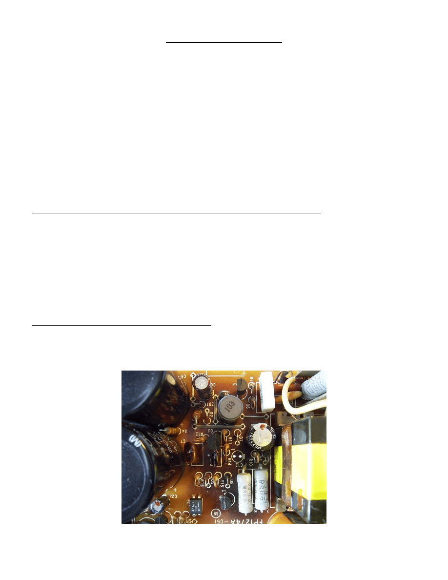
Step #2 – Visual inspection of the PSU board
The board is usually discolored between the two 470µF/200V electrolytic capacitors and
the transformer. The reason for this (and the short life of the capacitors) is two very hot
33ohm, 2W resistors (R17 and R18). See figure 1.
Fig 1. - Check C8, C9, C12 (C12 is removed here) and C22. They are likely out of spec.
Step #3 – Repair & replacement
a. I suggest you replace at least C8, C9, C12 or preferably all electrolytic capacitors on the
PSU PCB with +105 C versions, but not necessarily the rectifier filter's 470 uF/200 V big
caps, if they seem OK and you can measure their value or even better, the ESR too.
b. Replace R17 and R18 (optional) with a pair of 5W, 33ohm resistors (DigiKey p/n
45F33RE-ND). Install the new resistors on end, and do not trim the long lead…instead
coil it so that it can dissipate some of the heat from the resistor (wrap it around a drill bit
to coil it).
c. Re-solder (with fresh solder and flux) all the cracked or “cold” solder connections on the
PCB (especially around the transformer).
d. Remove solder splashes (and possible solder bridges) with brush carefully.
e. Reinstall the base plate, cage and secure the unit in place in the chassis and temporarily
connect the AC cable and see if the unit now works. If it does, unplug AC cord and now
reassemble the rest
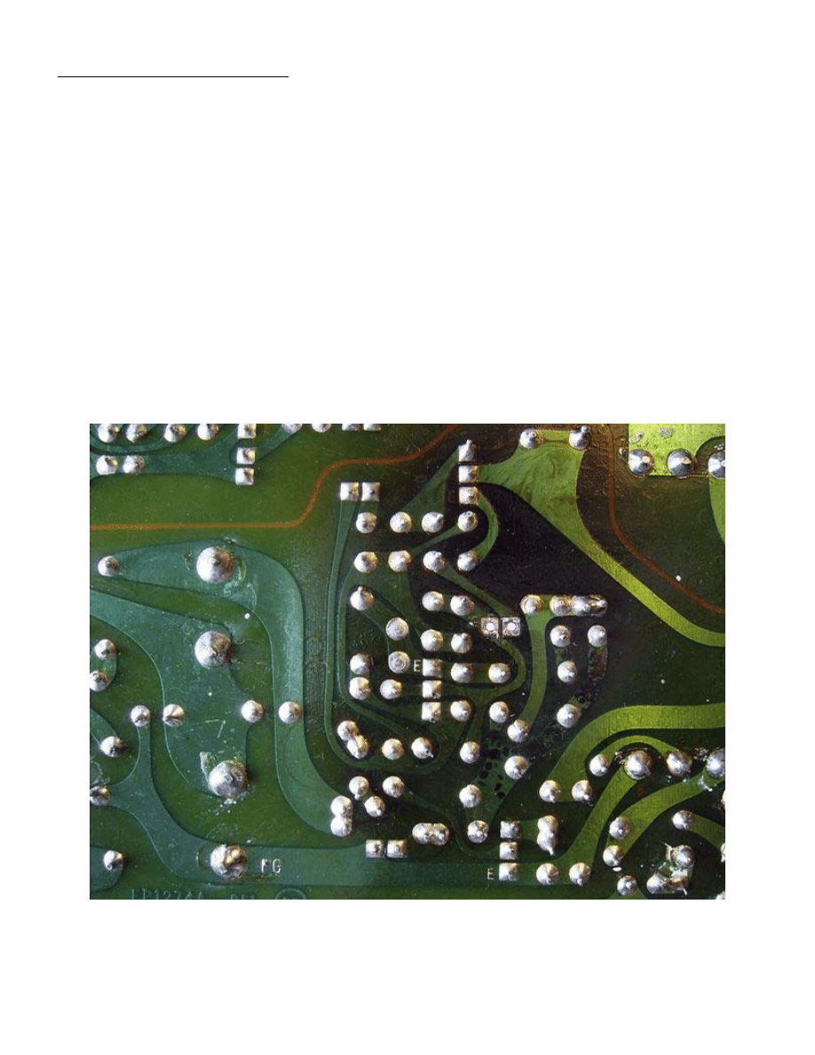
Fig 2. Thoroughly inspect the solder side of the board for cracked solder joints - the next
picture shows several bad joints.
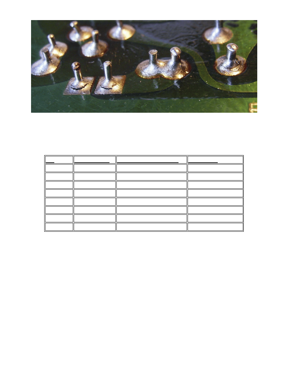
Fig 3. Close up photo showing cracked solder connections
DigiKey carries low ESR replacement capacitors (Nichicon FC Series):
Ref Existing
Value recommended
alternative DigiKey-p/n
C8 56µF/50V
P10322-ND
C9 220µF/16V
220uF/35V
P10297-ND
C12,C25 1µF/50V
P10312-ND
C21,C22 1000µF/25V
2700µF/25V
P10286-ND
C26 680µF/35V
1000µF/35V
P10305-ND
R17,R18* 33ohm, 2W
33ohm, 5W, 1%
45F33RE-ND
FAN*
n/a
6.8CFM (w/o zener)
CR015-ND
Zener*
n/a
5.1V, for fan speed reduction 1N4733AFSCT-ND
Table 1. Replacement Component list (* = optional items)
Step #4 – Optional Cooling Fan Installation
You can also install a 12V fan 40x40x10 mm inside the perforated box to reduce the component temperature
and improve their lifetime; DigiKey p/n: CR015-ND
You may install the fan in the middle of the PCB long side on the perforated cover - see pics. Test for
sufficient room between the fan and inside PCB components.
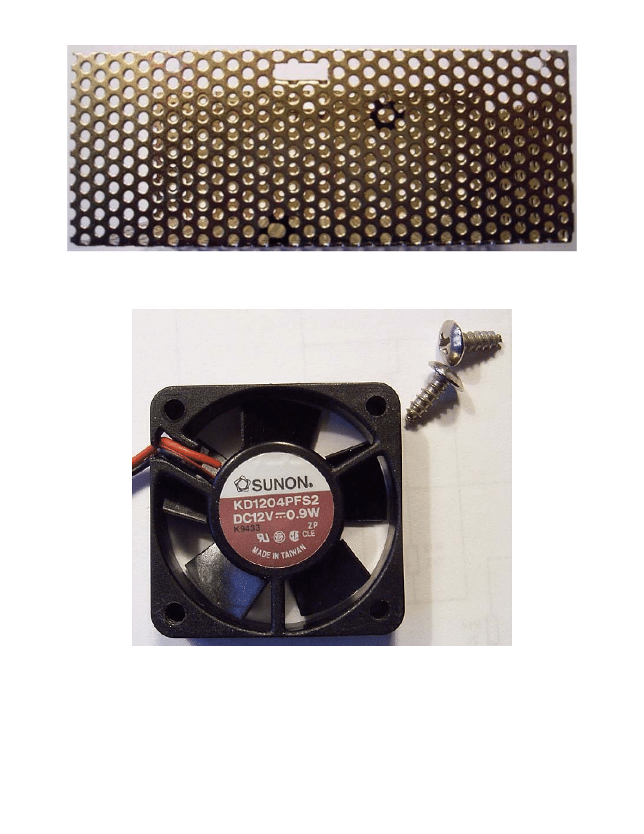
Fig 4. Modified cover with two oval shaped holes for the fan. These holes were enlarged up to 3.8 mm
before filing them into an oval shape.
Fig 5. Fan with 2 x 3.5 mm screws
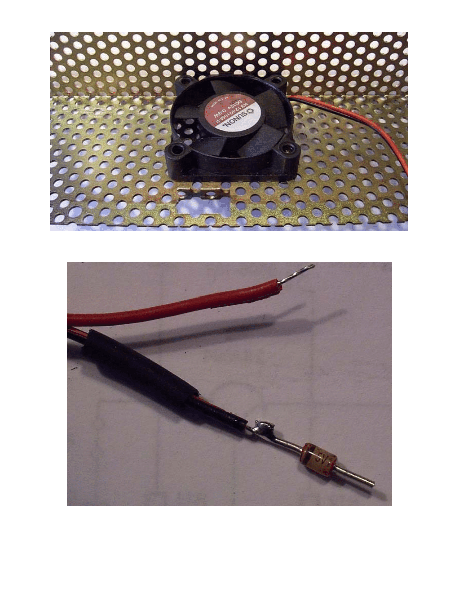
Fig 6. Fan at site, wires are cut 12 cm from fan
Fig 7. A 5V/1W zener diode plus a piece of shrink tube are added to the minus wire (the fan speed is reduced
to improve lifetime and reduce noise)
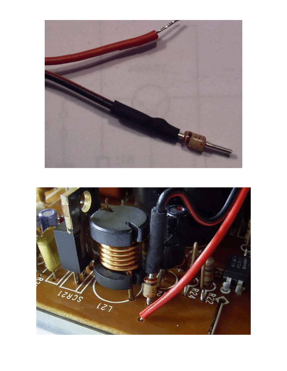
Fig 8. The wire and diode is ready to insert the PCB-holes and solder
Fig 9. Notice where and how the wire and diode are inserted into the PCB
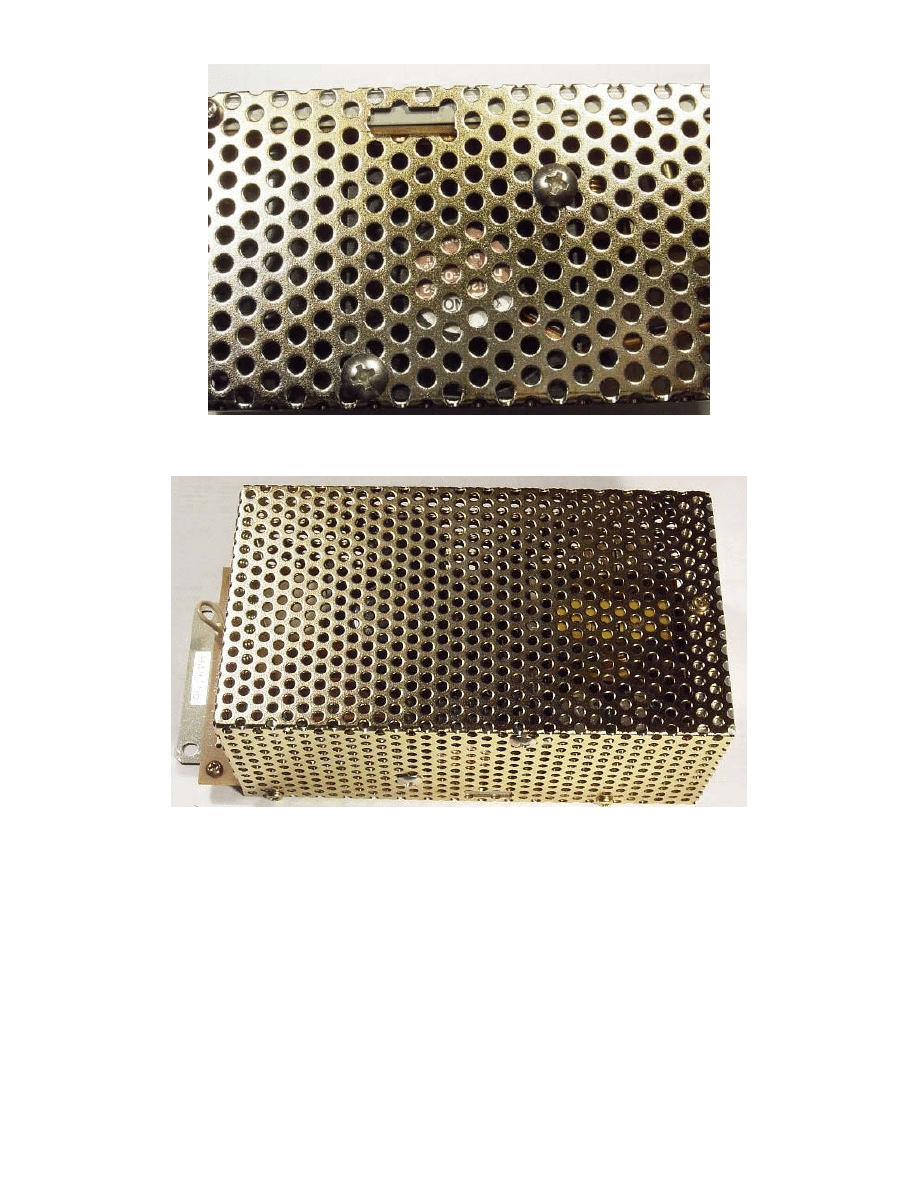
Fig 10. Showing the fan through the perforation
Fig 11. Completed power supply ready to install into FT-736R.
Be sure to roll and shake the unit to check for any loose parts inside. Remove any objects that
do not belong there.
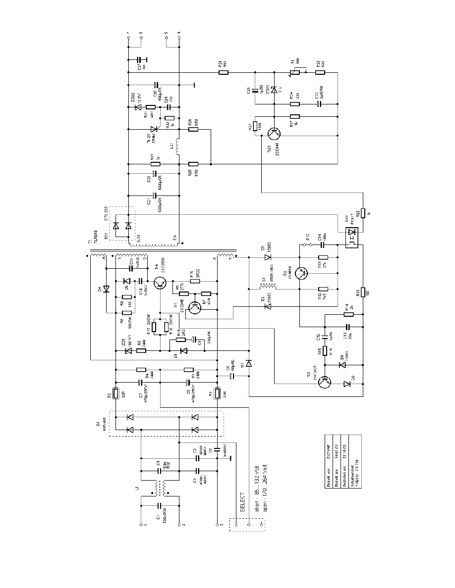
DL7VHF’s FT-736R Power Supply Schematic
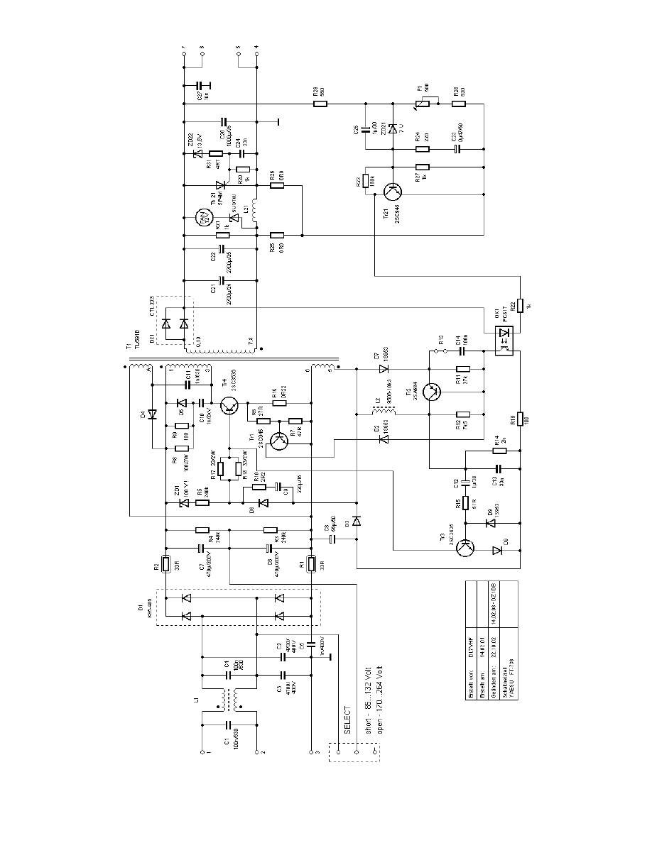
DL7VHF’s Modified FT-736R Power Supply Schematic
Wyszukiwarka
Podobne podstrony:
Yaesu FT 7800
YAESU FT 736 pwr Schematic
YAESU FT 8800 R E Brochure
YAESU FT 874 qst Review
YAESU FT 411mkII User manual
YAESU FT 100D Service Manual pages
Yaesu FT 7800 PL
YAESU FT 817 Broshure
YAESU Ft 7800 PL
ROZBLOKOWANIE Yaesu FT 817 (FT 817 FT817)
PS VI
PS spolecznosc lokalna 3
PS 1 Psychologia społeczna wstep
PS Organiz 11
PS Komunikacja 910
Semin 3 ST Ps kl Stres
PS IV
w2 ps poznawcza
Popular Mechanics Repairing Power Antennas
więcej podobnych podstron