
MPLS Traffic
Engineering Technology
Overview
The MPLS Traffic Engineering (TE) Technology module discusses the
requirement for traffic engineering in modern networks that must attain optimal
resource utilization. The traffic engineered tunnels provide a means of mapping
traffic streams onto available networking resources in a way that prevents the over
use of subsets of networking resources while others subsets are under-utilized.
All the concepts and mechanics that support traffic engineering are presented,
including the tunnel path discovery with link-state protocols and tunnel path
signaling with RSVP (Resource ReSerVation Protocol). Some of the advanced
features of traffic engineering such as autobandwidth and guaranteed bandwidth
are introduced as well.
Objectives
Upon completion of this module, you will be able to perform the following tasks:
■
Explain the need for traffic engineering to optimize network resources
■
Describe the concepts of MPLS traffic engineering
■
Identify MPLS traffic engineering features
■
Explain the tunnel path attributes and setup procedures
■
Describe the tunnel path maintenance
■
Explain the enhanced traffic engineering features such as autobandwidth or
guaranteed bandwidth

2
MPLS Traffic Engineering Technology
Copyright
2001, Cisco Systems, Inc.
Traffic Engineering Concepts
Objectives
Upon completion of this lesson, you will be able to perform the following tasks:
■
Explain the need for traffic engineering for the efficient use of network
resources
■
Describe the concepts of traffic engineering based on constraint-based path
selections
■
Explain the role of MPLS in traffic engineering

Copyright
2001, Cisco Systems, Inc.
MPLS Traffic Engineering Technology
3
© 2001, Cisco Systems, Inc.
MPLS Traffic Engineering Technology-5
Business Drivers for Traffic
Engineering
Business Drivers for Traffic
Engineering
•
Routers always forward traffic along the
least-cost route as discovered by intra-
domain routing protocol (IGP)
•
Network bandwidth may not be efficiently
utilized:
–
The least-cost route may not be the only
possible route
–
The least-cost route may not have enough
resources to carry all the traffic
In a layer-3 routing network, packets are forwarded hop-by-hop. In each hop the
destination address of the packet is used to make a routing table lookup. The
routing tables are created by an interior routing protocol, IGP, which finds the
least-cost route according to its metric to each destination in the network.
In many networks, this method works well. But in some networks the destination
based forwarding results in the over-utilization of some links while others are
under-utilized. This imbalance will be the case when there are several possible
routes to reach a certain destination and the IGP selects one of them as the best
and uses only that. In the extreme case, the best path may have to carry so large a
volume of traffic that packets are dropped while the non-best path is almost idle.
One solution to the problem would be to adjust the link bandwidths to more
appropriate values. Reduce the under utilized link and increase the over-utilized
one. However, this adjustment is not always possible. The alternate path is a
backup path. In the case of a primary link failure, the backup must be able to
forward at least the major part of the traffic volume normally forwarded by the
primary. Therefore it may not be possible to reduce the bandwidth. Without a cost
saving, the budget may not allow an increase to the primary link bandwidth.
In order to provide better network performance within budget, network
administrators move a portion of the traffic volume from the over-utilized link to
the under-utilized link. During normal operations, this move results in less packet
drops and quicker throughput. In the case of a failure to any of the links, all traffic
is forwarded over the remaining link, which then of course becomes over-utilized.
Moving portions of the traffic volume cannot be achieved by traditional hop-by-
hop routing using an IGP for path determination.

4
MPLS Traffic Engineering Technology
Copyright
2001, Cisco Systems, Inc.
© 2001, Cisco Systems, Inc.
MPLS Traffic Engineering Technology-6
Business Drivers (Cont.)
Business Drivers (Cont.)
•
Lack of resources results in congestion in
two ways:
–
When network resources themselves are
insufficient to accommodate offered load
–
When traffic streams are inefficiently
mapped onto available resources
•
Some resources are over-utilized while
others remain under-utilized
Network congestion caused by too much traffic and not enough network resources
cannot be solved by moving portions of the traffic between different links.
Moving the traffic will only help in the case where some resources are over-
utilized while others are under-utilized. The traffic streams in normal layer-3
routing are inefficiently mapped onto the available resources.
Good mapping of the traffic streams onto the resources creates a better use of the
invested money.
Cost savings that result in a more efficient use of bandwidth resources helps to
reduce the overall cost of operations. This reduction in turn helps service
providers gain an advantage over their competitors. This advantage becomes more
and more important as the service provider market gets more and more
competitive.
A more efficient use of bandwidth resources means that a provider could avoid a
situation where some parts of its network are congested, while other parts are
underutilized.

Copyright
2001, Cisco Systems, Inc.
MPLS Traffic Engineering Technology
5
© 2001, Cisco Systems, Inc.
MPLS Traffic Engineering Technology-7
Congestion Avoidance
Congestion Avoidance
•
Network congestion can be addressed by
either:
–
Expansion of capacity or classical
congestion control techniques (queuing,
rate limiting...)
–Traffic Engineering (TE)
, if the problems
result from inefficient resource allocation
•
Focus of TE is not on congestion created as
a result of a short term burst, but on the
congestion problems that are prolonged
Traffic engineering does not solve temporary network congestion caused by
bursty traffic. This type of problem is better handled by an expansion of capacity
or by classical techniques such as various queuing algorithms, rate limiting and
intelligent packet dropping.
Traffic Engineering (TE) is used when the problems result from inefficient
mapping of traffic streams onto the network resources. In such networks, one part
of the network suffers from congestion during long periods of time, possibly
continuously, while other parts of the network have spare capacity.

6
MPLS Traffic Engineering Technology
Copyright
2001, Cisco Systems, Inc.
© 2001, Cisco Systems, Inc.
MPLS Traffic Engineering Technology-8
What Is Traffic Engineering?
What Is Traffic Engineering?
•
Term in common use in telephone voice
network world
•
Measures, models, and controls traffic to
achieve various goals
•
Provides an integrated approach to
engineering traffic at layer-3 in the Open
System Interconnection reference model
The term Traffic Engineering (TE) is widely used in the telephone voice world.
TE means that the traffic is measured and analyzed. Then a statistical model is
applied to the traffic pattern to make a prognosis and estimations. If the
anticipated traffic pattern does not match well with the network resources, the
network administrators remodels the traffic pattern. Such decisions can be made
to achieve a more optimum use of their own resources or to reduce costs by
selecting a cheaper transit carrier.
In the data communications world, traffic engineering provides an integrated
approach to engineering traffic at layer-3 in the OSI model. The integrated
approach means that routers are configured to divert from destination based
forwarding to move the traffic load from congested parts of the network to non-
congested parts. Traditionally, this diversion was done using overlay networks
where routers use carefully engineered ATM or Frame Relay PVCs to distribute
the traffic load on layer-2.

Copyright
2001, Cisco Systems, Inc.
MPLS Traffic Engineering Technology
7
© 2001, Cisco Systems, Inc.
MPLS Traffic Engineering Technology-9
Traffic Engineering Motivations
Traffic Engineering Motivations
•
Reduce the overall cost of operations by
more efficient use of bandwidth resources
•
Prevent a situation where some parts of a
service provider network are over-utilized
(congested), while other parts remain under-
utilized
Cost reduction is the main motivation for Traffic Engineering.
A cost savings that result from a more efficient use of resources help to reduce the
overall cost of operations..
Additionally, more efficient use of bandwidth resources means that a provider
could avoid a situation where some parts of its network are congested, while other
parts are under-utilized.
8
MPLS Traffic Engineering Technology
Copyright
2001, Cisco Systems, Inc.
© 2001, Cisco Systems, Inc.
MPLS Traffic Engineering Technology-10
Implementing Traffic Engineering
with Layer-2 Overlay Model
Implementing Traffic Engineering
with Layer-2 Overlay Model
•
The use of the explicit layer-2 transit layer allows very
exact control of how traffic uses the available
bandwidth
•
Layer-3 at the edge sees a complete mesh
L3
L3
L3
L3
L3
L3
L3
L2
L2
L2
L2
L2
L2
L3
L3
L3
L3
L3
Physical
Logical
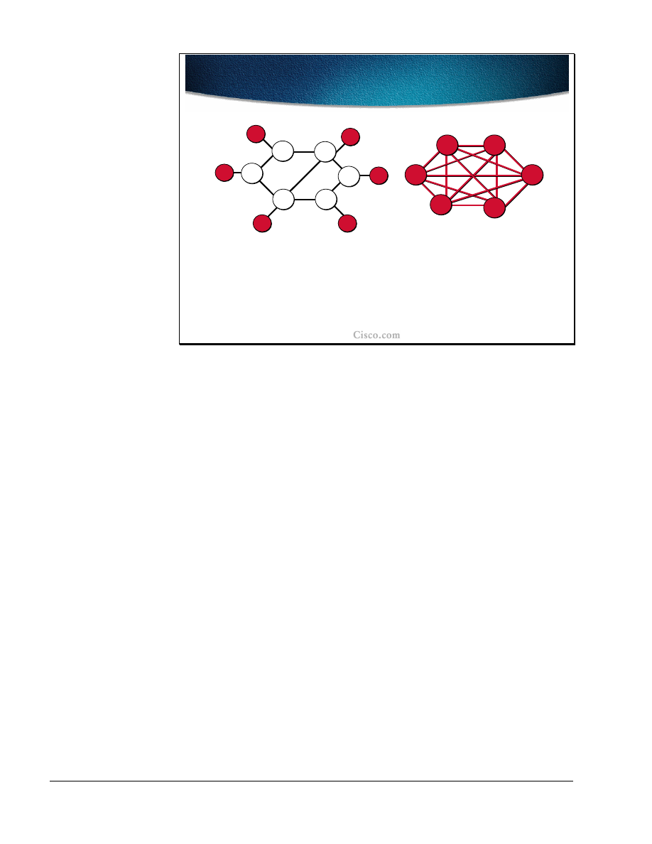
In the overlay model, the routers (layer-3 devices) are not aware of the physical
structure and the bandwidth available on the links. The IGP views the PVCs or
SVCs as point to point links and makes its forwarding decisions accordingly.
Instead all engineering is done at layer-2. PVCs are carefully engineered across
the network, normally using an off-line management system. SVCs are
automatically established using signaling and their way across the layer-2 network
is controlled by an integrated path determination such as the PNNI protocol.
If the layer-2 network provides a full mesh between all routers, the layer-3 IGP
sees all the other routers as directly connected, and, most likely, uses the direct
logical link whenever forwarding a packet to another router. The full mesh gives
the layer-2 full control of the traffic load distribution. Manual engineering of
PVCs and/or the configuration of PNNI parameters are the tools that allow a very
exact control of how the traffic uses the available bandwidth.

Copyright
2001, Cisco Systems, Inc.
MPLS Traffic Engineering Technology
9
© 2001, Cisco Systems, Inc.
MPLS Traffic Engineering Technology-11
Overlay Model Characteristics
Overlay Model Characteristics
•
Permanent virtual circuits (PVC) carry traffic across
layer-2
•
Switched virtual circuits (SVC) are established via
signaling
–
Example: ATM SVCs
•
Router signals the request to establish a
switched virtual circuit to the ATM switch using
the UNI (User-Network Interface) protocol
•
The ATM switch opens this SVC using the PNNI
(Private-Network-to-Network-Interface) protocol
In the overlay model, PVCs or SVCs carry the traffic across the network.
In the case of a Frame Relay network, a PVC setup is most often made using a
management tool, which helps the network administrator calculate the optimum
path across the layer-2 network with respect to available bandwidth and other
constraints that may be applied on individual links.
ATM uses either the same type of tools as Frame Relay for PVC establishment or
it may use the SVC approach where routers use a signaling protocol to
dynamically establish a switched virtual circuit. When SVCs are used, the router
merely asks for an SVC with certain attributes to the other router using the ATM
Forum specified signaling protocol. The layer-2 network then opens this SVC
internally using the PNNI (Private-Network-to-Network-Interface) protocol.
PNNI, in the head end ATM switch, uses link-state information to pre-calculate a
Designated Transit List (DTL), which describes the suggested total path across
the ATM network. This suggested path is then validated across the ATM network
by each hop switch, which then provide the SVC.

10
MPLS Traffic Engineering Technology
Copyright
2001, Cisco Systems, Inc.
© 2001, Cisco Systems, Inc.
MPLS Traffic Engineering Technology-12
Example: Traffic Engineering with
Overlay
Example: Traffic Engineering with
Overlay
R2
R3
R1
PVC for R2 to R3 traffic
PVC for R1 to R3 traffic
Traffic engineering in layer-2 using the overlay model, allows for detailed
decisions regarding which link should be used to carry different traffic patterns.
In the example in the figure, traffic from R2 to R3 uses a PVC, which takes the
shortest path using the upper transit switch. However, traffic from R1 to R3 uses a
PVC, which does not take the shortest path. Traffic Engineering on layer-2 is
applied to let the PVC use links that would otherwise have been under-utilized
and thereby avoids over-utilization of the upper path.

Copyright
2001, Cisco Systems, Inc.
MPLS Traffic Engineering Technology
11
© 2001, Cisco Systems, Inc.
MPLS Traffic Engineering Technology-13
Drawbacks of the Overlay
Solution
Drawbacks of the Overlay
Solution
•
Extra network devices
•
More complex network management
–
Two-level network without integrated network
management
–
Additional training, technical support, field
engineering
•
IGP routing scalability issue for meshes
•
Additional bandwidth overhead (“cell tax”)
•
No differential service (Class of Service)
Using the overlay model has several drawbacks:
■
The routers are not physically connected to other routers. The layer-2 network
introduces the need for an additional device, the ATM or Frame Relay switch.
■
Two networks must be managed. The layer-2 network requires its own
management tools, which among several other tasks support the traffic
engineering as well. At the same time, the router network (layer-3) with its
IGP and tuning parameters must be managed. Both these management tasks
require trained staff for technical support and in the field.
■
The layer-3 network must be highly meshed in order to take advantage of the
benefits provided by the layer-2 network. The highly meshed network may
cause scalability problems for the IGP because of the large number of
neighbors.
■
Overlay networks always require an extra layer of encapsulation. A Frame-
Relay header must be added to the IP packets, or, when ATM is used, the IP
packet must be segmented into cells, each of which must have its own header.
The extra layer of encapsulation causes bandwidth overhead.
■
The layer-2 devices do not have any layer-3 knowledge. Once the router has
transmitted the IP packet across the physical link to the first switch, all IP
knowledge is lost. When congestion does occur in the layer-2 network, the
switches have no ability to selectively discard IP packets or to re-queue them
due to prioritization. No IP differentiated services can be used within the layer
2 switch network.
12
MPLS Traffic Engineering Technology
Copyright
2001, Cisco Systems, Inc.
© 2001, Cisco Systems, Inc.
MPLS Traffic Engineering Technology-14
Implementing Traffic Engineering
with Layer-3 Model
Implementing Traffic Engineering
with Layer-3 Model
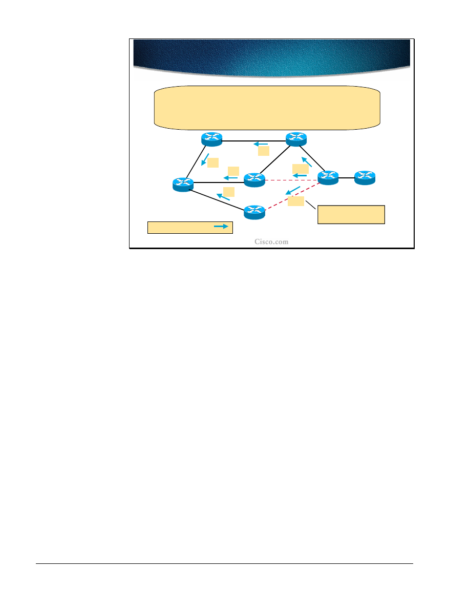
R8
R2
R6
R3
R4
R7
R5
R1
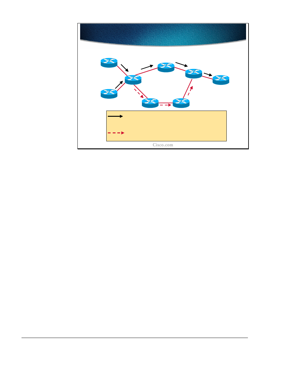
IP (mostly) uses destination based least-cost routing.
Flows from R8 and R1 merge at R2. From R2, traffic to
R3, R4, and R5 use the upper route.
The dashed arrow denotes an underutilized alternative
path.
If the same network topology is created using routers (layer-3 devices), traffic
engineering must be performed differently.
■
If no traffic engineering is applied to this network, traffic from both R8 and
R1 towards R5 will use the least cost path (the upper path). This flow may
result in the over-utilization of the path R2, R3, R4, R5 while the path R2, R6,
R7, R4, R5 is under-utilized.

Copyright
2001, Cisco Systems, Inc.
MPLS Traffic Engineering Technology
13
© 2001, Cisco Systems, Inc.
MPLS Traffic Engineering Technology-15
Routing Solution to Traffic
Engineering
Routing Solution to Traffic
Engineering
•
The current forwarding paradigm, centered
around “destination-based” is clearly
inadequate
–
Path computation based just on IGP metric
is not enough
–
Support for “explicit” routing (source
routing) is not available
–
Supported workarounds: static routes,
policy routing
The destination-based forwarding paradigm currently used in layer-3 networks
cannot handle the problem with over-utilization of one path while the alternate
path is under utilized.
The IGP uses its metric to compute a single best way to reach each destination.
Alternate routes with a higher metric are not used at all.
IP source routing could be used to override the IGP created routing table in each
of the intermediate routers. However in a service provider network, source routing
is most often prohibited. The source routing would also require the host to create
the IP packets to request source routing. The conclusion is that source routing is
not an available tool for traffic engineering.
Static routing, which overrides the IGP can be used to direct traffic to take a
different path than traffic towards other destinations. However, static routing does
not make it possible to discriminate between different traffic flows based on the
source. Static routing also implies restrictions in how redundancy in the network
can be used.
Policy based routing is able to discriminate packet flows based on the source, but
suffers from low scalability and the same static routing restrictions as to how
redundancy.

14
MPLS Traffic Engineering Technology
Copyright
2001, Cisco Systems, Inc.
© 2001, Cisco Systems, Inc.
MPLS Traffic Engineering Technology-16
Using MPLS to Implement Traffic
Engineering (MPLS-TE)
Using MPLS to Implement Traffic
Engineering (MPLS-TE)
•
The idea of MPLS-TE is based on Multiprotocol
Label Switching (MPLS) that integrates a label
swapping framework with network layer routing
–
Packets at the ingress are assigned labels through
Tag Distribution Protocol or Label Distribution
Protocol
•
Also MP-BGP for Virtual Private Networks
–
Labels represent the path through the system
(Label Switched Path)
–
Forwarding within the MPLS network is based on
labels (no layer-3 lookup)
MPLS Traffic Engineering (MPLS-TE) means that the routers use the MPLS
label-switching/tag-switching paradigm. Labels are assigned and distributed
between routers using the Label Distribution Protocol (LDP) or the Tag
Distribution Protocol (TDP). Packets are assigned labels by the ingress router, and
the packet is then forwarded across the network using label switching based solely
on the label, and not on the IP header information. At the egress router, the label
is removed and the packet is again forwarded as an IP packet.
When full label information is exchanged, any router can reach any other router
within the MPLS domain using label switching. In other words, a Label Switching
Path (LSP) exists between all routers.
The existing LSPs or newly created ones between the routers are used by MPLS
applications such as Virtual Private Networks (MPLS-VPN) and Traffic
Engineering (MPLS-TE). A stack of two labels is imposed to the IP packet by the
ingress router. The top-most label value is used to let the packet traverse the
desired LSP to the router at the other end. The next label is then used by that
router to indicate further actions.
In MPLS-VPN, Multi-Protocol-BGP (MP-BGP) is used to distribute the second
label in the stack used for telling the egress PE router how to forward the
incoming VPN packet.

Copyright
2001, Cisco Systems, Inc.
MPLS Traffic Engineering Technology
15
© 2001, Cisco Systems, Inc.
MPLS Traffic Engineering Technology-17
Forwarding in MPLS-TE
Forwarding in MPLS-TE
•
In MPLS-TE labels can be created through
manual administrative action or through
automated action by the underlying
protocols
–
Forwarding is based on explicit MPLS
Label Switched Paths
–
MPLS-TE provides benefits similar to the
overlay model, but without:
•
Separate layer-2 network
•
Non-scalable full mesh of router
interconnections
For MPLS-TE, manual assignment and configuration of the labelscan be used to
create LSPs to tunnel the packets across the network on the desired path.
However, to increase scalability, the ReSource Reservation Protocol (RSVP) is
used to automate the procedure.
The packets forwarded according to MPLS-TE have a stack of two labels
(imposed by the ingress router). The top-most label identifies a specific LSP to
use to reach another router at the other end of the tunnel. The second label
indicates what the router at the far end of the LSP should do with the packet.
By selecting the appropriate LSP, traffic can be directed via explicitly indicated
routers. The explicit path across identified routers provides similar benefits to the
overlay model without introducing a layer-2 network and also without the risk of
running into IGP scalability problems due to the many neighbors existing in a full
mesh of routers.

16
MPLS Traffic Engineering Technology
Copyright
2001, Cisco Systems, Inc.
© 2001, Cisco Systems, Inc.
MPLS Traffic Engineering Technology-18
Overview of IP Mechanisms for
Traffic Engineering
Overview of IP Mechanisms for
Traffic Engineering
• Circuit-style forwarding:
MPLS
• Signaling:
Resource Reservation Protocol (RSVP)
• Constraint-based routing:
extended Intermediate
System-to-Intermediate System (ISIS) or Open
Shortest Path First (OSPF)
• Routing onto tunnels:
extended
(tunnel-aware) IS-IS/OSPF shortest path first
algorithm
• Forwarding:
Installation of tunnels in the Forwarding
Information Base
MPLS-TE provides equivalent mechanisms to those described on previous slides
in the overlay network. For circuit-style forwarding, instead of using ATM or
Frame Relay virtual circuits,
MPLS TE tunnel is used
. For signaling, RSVP is
used with various extensions to set up the MPLS-TE tunnels.
For constraint-based routing, either IS-IS or OSPF with extensions is used to carry
resource information like available bandwidth on the link. Both link-state
protocols use new attributes to describe the nature of each link with respect to the
constraints.. A link that does not have the required resource is not included in the
LSP, which constitutes the MPLS-TE tunnel.
To actually direct the traffic onto the MPLS-TE tunnels, extensions to IS-IS and
OSPF are needed. . Directing the traffic onto tunnels results in the adding of
entries in the Forwarding Information Base (FIB), the CEF-cache. The IP packets
are directed into the MPLS-TE tunnel by imposing the correct label stack.

Copyright
2001, Cisco Systems, Inc.
MPLS Traffic Engineering Technology
17
© 2001, Cisco Systems, Inc.
MPLS Traffic Engineering Technology-19
Overview of Acronyms
Overview of Acronyms
• MPLS
—Multi-Protocol Label Switching (formerly
known as Tag Switching).
• MPLS-TE
—MPLS Traffic Engineering (formerly
known as "RRR" or Resource Reservation Routing).
The use of label switching to improve traffic
performance along with an efficient use of network
resources.
• CBR
—Constraint-based Routing. The computation of
traffic paths that simultaneously satisfy Label
Switched Path attributes and current network
resource limitations.
–
CBR is also referred as Path Calculation (
PCALC)
or Constrained SPF
(CSPF)
The following is a list of acronyms that is commonly used with MPLS Traffic
Engineering:
■
MPLS: Multi-Protocol Label Switching (formerly known as Tag Switching).
■
MPLS-TE: MPLS Traffic Engineering (formerly known as "RRR" or
Resource Reservation Routing). The use of label switching to improve traffic
performance along with an efficient use of network resources.
■
CBR: Constraint-based Routing. The computation of traffic paths that
simultaneously satisfy Label Switched Path attributes and current network
resource limitations.

18
MPLS Traffic Engineering Technology
Copyright
2001, Cisco Systems, Inc.
© 2001, Cisco Systems, Inc.
MPLS Traffic Engineering Technology-20
Overview of Acronyms (Cont.)
Overview of Acronyms (Cont.)
• LSP
—Label Switched Path.
• TT
—Trafic trunk (MPLS-TE tunnel). A Label Switched
Path tunnel configured between two routers.
• CEF
—Cisco Express Forwarding.
• RSVP
—Resource reSerVation Protocol. An IETF
protocol used for signaling requests.
• TDP/LDP
-Tag Distribution Protocol and standard
Label Distribution Protocol.
• LCAC
—Link-level (per-hop) Call Admission Control.
The following MPLS-TE acronyms are also used very often:
■
LSP: Label Switched Path. The path between two systems encoded with a
sequence of MPLS labels.
■
TT: Traffic trunk (MPLS-TE tunnel). A Label Switched Path tunnel
configured between two routers.
■
CEF: Cisco Express Forwarding.
■
RSVP: Resource reSerVation Protocol. An IETF protocol used for signaling
requests.
■
TDP/LDP: Tag Distribution Protocol and standard Label Distribution
Protocol.
■
LCAC: Link-level (per-hop) Call Admission Control.
■
Most of the terminology used throughout this document can be found in the
following documents:
■
RSVP-TE: Extensions to RSVP for LSP Tunnels, draft-ietf-mpls-rsvp-lsp-
tunnel-08.txt, IETF Network Working Group, February 2001
■
MPLS Traffic Engineering, RFC-2702, IETF Network Working Group,
September 1999

Copyright
2001, Cisco Systems, Inc.
MPLS Traffic Engineering Technology
19
Summary
After completing this lesson, you should be able to perform the following tasks:
■
Explain the need for traffic engineering for efficient usage of network
resources
■
Describe the concepts of traffic engineering based on constraint-based path
selections
■
Explain the role of MPLS in traffic engineering
Lesson Review
1. How can an overlay network provide traffic engineering?
2. What are the drawbacks of using overlay networks?
3. Why does traditional IP packet forwarding not distribute the load over all
links?
4. Can IP source-routing be used to overcome the problems of overlay networks?
5. Can policy-based routing be used to overcome the problems of overlay
networks?
6. What does MPLS provide that allows for Traffic Engineering?
7. Which IGPs can be used to calculate an LSP for an MPLS-TE tunnel?
8. How is the MPLS-TE LSP created?

20
MPLS Traffic Engineering Technology
Copyright
2001, Cisco Systems, Inc.
MPLS Traffic Engineering Components
Objectives
Upon completion of this lesson, you will be able to perform the following tasks:
■
List the components of MPLS traffic engineering
■
Explain the tunnel and link attributes
■
Describe the constraint-based path computation
■
Describe the role of RSVP in path setup procedures
■
Describe the forwarding table modification mechanisms

Copyright
2001, Cisco Systems, Inc.
MPLS Traffic Engineering Technology
21
© 2001, Cisco Systems, Inc.
MPLS Traffic Engineering Technology-26
Traffic Trunks and Trunk
Attributes
Traffic Trunks and Trunk
Attributes
•
The concept of Traffic Trunks (MPLS-TE
Tunnel) is introduced to overcome the
limitations of hop-by-hop IP routing
–
TT is an aggregation of traffic flows of the
same class (bandwidth...) which are placed
inside a common MPLS Label Switched
Path
–
TT flows are then forwarded along a
common path within a service provider
network
The aim of Traffic Engineering is to control the paths along which data flows,
rather than relying simply on ‘normal’ destination-based routing. To fulfill this
aim, the concept of a ‘Traffic Trunk’ must be introduced.
A Traffic Trunk is simply a collection of data flows, which share some common
attribute:
■
Most simply, this attribute might be traffic sharing the same entry point to the
network and the same exit point. A case of this in practice would be an
Internet Service Provider network, where there is a definable data flow from
the Points of Presence (POP), where the customers attach to the ISP network,
- to the Internet eXchange points (IX), where their data typically leaves this
ISP network to traverse the internet.
■
In a more complex situation, this attribute could be augmented by defining
separate trunks for different classes of service. For example, in an ISP model,
leased-line corporate customers could be given a preferential throughput
(greater guaranteed bandwidth or lower latency/higher precedence) over the
dial-in home users. Even though the traffic enters and leaves the ISP network
at the same points, different characteristics may be assigned to these types of
users by defining separate Traffic Trunks for their data.

22
MPLS Traffic Engineering Technology
Copyright
2001, Cisco Systems, Inc.
© 2001, Cisco Systems, Inc.
MPLS Traffic Engineering Technology-27
Traffic Trunk Usage in Unicast
Model
Traffic Trunk Usage in Unicast
Model
TT 1
TT 2
TT 3
R2
R1
R3
R4
In an unidirectional
single class service
model, a traffic trunk can
encapsulate all of the traffic between an ingress and an egress router
(e.g. BGP next-hops of POPs).
In a more complex situation, the traffic for
different classes of service
is assigned into separate TTs with different characteristics.
Defining the Traffic Trunks requires an understanding of the traffic flows in the
network. From the understanding of the ingress and corresponding egress points, a
picture of the traffic flows in the network can be produced.
In the example shown, there are Traffic Trunks (TT1, TT2 and TT3) defined for
data from R1 to R2, R3 and R4. These trunks are uni-directional; they identify
the traffic flows from R1. In practice, there are probably similar trunks operating
in the opposite direction to R1.
There may also be trunks defined from all the other routers to each other. -
Defining trunks from every router in the network to every other one might sound
like an administrative nightmare: However, this is not usually the case:
■
The routers identified are on the edge of the network. The traffic trunks link
these routers across the core of the network (colored green)
■
In most networks it is relatively easy to identify the traffic flows and they
rarely form a complete ‘any-to-any’ mesh.
■
For example, in ISP networks, the traffic trunks would generally form a
number of ‘star’ formations with their centers at the Internet Exchange points
and theother points at the POPs. Traffic in an ISP network generally flows
from the customers connected at the POPs to the rest of the Internet (reached
via the IX points). A star-like formation could also exist in many networks
centering on the Data-Center: both for ISP networks (providing web-hosting
services) and enterprises.

Copyright
2001, Cisco Systems, Inc.
MPLS Traffic Engineering Technology
23
© 2001, Cisco Systems, Inc.
MPLS Traffic Engineering Technology-27
TT Characteristics
TT Characteristics
•
Traffic trunks are routable objects (similar to
ATM VCs)
•
A traffic trunk is distinct from the MPLS LSP
through which it traverses
–
In operational contexts, a traffic trunk can
be removed from one path onto another
•
A traffic trunk is assigned attributes
influencing its characteristics
Once the data flows, and therefore the Traffic Trunks are defined, the technology
they use to send the data across the network is MPLS. Data entering a Traffic
Trunk is assigned an MPLS Label-Switch-Path, which defines the route taken
through the network. However, Traffic Trunks are distinct from the MPLS LSPs
they use in two key ways:
■
There is not necessarily a one-to-one mapping of Traffic Trunks on to MPLS
LSPs. For administrative reasons, two Trunks may be defined between two
points and may happen to pick the same path through the network. Therefore
they both have the same MPLS label.
■
Also, Traffic Trunks are not necessarily bound to a particular path through the
network. As resources change in the core, or perhaps links fail, the Traffic
Trunk may re-route, picking up a new MPLS LSP as it does.
The configuration of the Traffic Trunks includes defining the characteristics and
attributes it requires. Defining the Traffic Trunks characteristics and attributes is
probably the most important aspect of Traffic Engineering. Without specifying
the requirements of the data in this Traffic Trunk, the data may as well be left to
route ‘normally’ based on destination information only over the least cost path.

24
MPLS Traffic Engineering Technology
Copyright
2001, Cisco Systems, Inc.
© 2001, Cisco Systems, Inc.
MPLS Traffic Engineering Technology-29
Traffic Trunk Attributes
Traffic Trunk Attributes
•
Attributes are explicitly assigned to traffic
trunks through administration action
•
A traffic trunk is characterized by:
–
Its ingress and egress Label Switch
Routers
–
The forwarding equivalence class which is
mapped onto it
–
A set of attributes which determine its
characteristics
A Traffic Trunk is a set of data flows sharing some common feature, attribute or
requirement. If there is no characteristic in the data flow to make it common with
some other flow, there is nothing to define that data as part of a flow or group of
flows.
Therefore, the Traffic Trunk, in its very definition, must include the definition of
those attributeswhich define the commonality between the data flows making up
the Trunk. The attributes that characterize a Traffic Trunk includes:
■
Most fundamentally, the ingress and egress points: the routers at the ends of
the Trunk. This is the most basic level of commonality between data flows;
they start in the same place and end in the same place.
■
More complex characteristics of the data flows, such as bandwidth and
latency/precedence requirements.
■
The class of data: what data is ‘part of’ this Trunk and what is not (which in
itself is a combination of the above)
The attributes of a Traffic Trunk are defined by the network administrator when
the Trunk is defined, however, some of them are in part influenced by the
uderlying network and protocols.

Copyright
2001, Cisco Systems, Inc.
MPLS Traffic Engineering Technology
25
© 2001, Cisco Systems, Inc.
MPLS Traffic Engineering Technology-29
Traffic Trunks
Traffic Trunks
•
The operator enters the relevant information
(attributes) at the ends of the traffic trunks
– Traffic parameter
– resources required for trunk
(e.g., required bandwidth)
– Generic path selection and management
– path
can be administratively specified or computed by
the IGP
– Resource class affinity
- include/exclude certain
links for certain traffic trunks
– Adaptability
- shall the traffic trunk be re-optimized
The characteristics, which define the trunk are configured by the network
operator, include some or all of the following:
■
Traffic Parameters: the resources required by the trunk, such as the minimum
required bandwidth.
■
Generic Path Selection and Management: the path selection criteria. The
actual path chosen through the network could be statically configured by the
operator or could be assigned dynamically by the network based on
information from the IGP (IS-IS or OSPF).
■
Resource Class Affinity: restricting the choice of paths by allowing the
dynamic path to choose only certain links in the network rather than being
allowed to use any link.
■
Adaptability: the ability of the path to re-route on failure or to optimize on
recovery/discovery of the ‘better’ path.

26
MPLS Traffic Engineering Technology
Copyright
2001, Cisco Systems, Inc.
© 2001, Cisco Systems, Inc.
MPLS Traffic Engineering Technology-30
Traffic Trunks (Cont.)
Traffic Trunks (Cont.)
• Priority/Preemption
- importance of a traffic
trunk and possibility for a preemption of
another trunk
• Resilience
- desired behavior under fault
conditions
• Policing
- to enforce compliance with service
level agreements (e.g., treatment of the non-
conformant traffic trunk traffic)
Continuing the list of Traffic Trunk parameters:
■
Priority/Pre-emption: Traffic Trunks can be assigned a priority (0 to 7)
signifying their ‘importance’. When setting up a new trunk or re-routing, a
higher priority trunk can tear down (preempt) a lower priority trunk; or a
new trunk of lower priority may fail to set up because some trunks of a
higher priority already exist occupying the required bandwidth of the lower
priority trunk.
■
Resilience: What happens to a Traffic Trunk in the event of a failure in the
network. Does it attempt to re-route around failures or not?
■
Policing: How the trunk enforces compliance to the service-level (bandwidth,
precedence) and what it does with traffic, which exceeds the service-level
(examples, drop non-conforming data or send it as ‘best effort’).

Copyright
2001, Cisco Systems, Inc.
MPLS Traffic Engineering Technology
27
© 2001, Cisco Systems, Inc.
MPLS Traffic Engineering Technology-31
Constrained Path Setup and Link
Resource Attributes
Constrained Path Setup and Link
Resource Attributes
•
MPLS-TE creates one or more explicit paths
with bandwidth assurances for each traffic
trunk
–
Additional information about the state of
the network is needed
•
Link resource attributes (link availability) are
used to constrain the routing of traffic trunks
through specific resources
At the heart of MPLS Traffic Engineering is the ability to define trunks through
the network, each with an assured amount of bandwidth.
Information must be given to the MPLS processes to create and define the Label
Switched Path through the network. This information may come from an explicit
configuration (manually defining a fixed LSP ) or from a dynamic path-
assignment process.
In order to dynamically provide the MPLS LSP which provides a guaranteed
bandwidth, information must be gathered from around the network about the state
of the network and the bandwidth available on the individual links in the network.
Therefore link resource information must be sent to the routers terminating the
Traffic Trunks so they can calculate a LSP that will provide the level of
bandwidth required.

28
MPLS Traffic Engineering Technology
Copyright
2001, Cisco Systems, Inc.
© 2001, Cisco Systems, Inc.
MPLS Traffic Engineering Technology-32
Example: Modeling Traffic Trunk
Request
Example: Modeling Traffic Trunk
Request
TT 1
TT 2
R2
R1
R3
R4
Traffic originating from R1 and destined for R3 and R4 shall be
classified into two trunks providing guaranteed bandwith of
1 Mbps between R1 and R3 and 500 Kbps between R1 and R4.
Boundary routers objective:
Let’s find the best paths for the traffic
trunks based on the requested bandwidth. The path is encoded as
a sequence of MPLS labels.
An example network is shown in the figure.
In this example R1 is carrying traffic destined for the other side of the network.
Specifically, some traffic is destined for R3 and some for R4.
The traffic profiles identified have shown a requirement for a minimum
bandwidth of 1Mbps from R1 to R3 and 500kbps from R1 to R4.
In order to carry this defined traffic across the network, two Traffic Trunks are
required. R1, which is the head-end router, must create these two trunks. In order
to do this, R1 must define the LSP for each trunk through the core of the network
and assign the appropriate MPLS labels to the trunks (and therefore to the data
using those trunks).
R1 must collate information about the network and then issue the request for
building the trunks over the appropriate LSPs.

Copyright
2001, Cisco Systems, Inc.
MPLS Traffic Engineering Technology
29
© 2001, Cisco Systems, Inc.
MPLS Traffic Engineering Technology-33
Basic Operations on Traffic
Trunks
Basic Operations on Traffic
Trunks
• Establish:
To create an instance of a traffic
trunk.
• Activate/Deactivate:
To cause a traffic trunk
to start and stop passing traffic.
• Modify Attributes:
To cause the attributes of
a traffic trunk to be modified.
• Reroute:
To cause a traffic trunk to change
its route.
• Destroy:
To remove an instance of a traffic
trunk from the network and reclaim all
resources allocated to it.
There are various processes, which may occur in the lifetime of a Traffic Trunk:
■
Establish: Creating a Traffic Trunk by deciding on the LSP through the
network, assigning MPLS labels and, most importantly, assigning resources to
the Trunk.
■
Activate: Causing data to start to use the Traffic Trunk by using some routing
function, which directs traffic into the Trunk.
■
Deactivate: Stopping data from using the Traffic Trunk by again using a
routing function to cease the direction of data into the Trunk.
■
Modify Attributes: Changing the characteristics of the Traffic Trunk (such as
its available bandwidth).
■
Re-route: Choosing a new path for the Traffic Trunk (most probably because
of some failure in the network, or a recovery from a failure).
■
Destroy: Removing the Traffic Trunk completely by reclaiming the resources
allocated and perhaps the MPLS labels.

30
MPLS Traffic Engineering Technology
Copyright
2001, Cisco Systems, Inc.
© 2001, Cisco Systems, Inc.
MPLS Traffic Engineering Technology-35
Network Links and Link Attributes
Network Links and Link Attributes
•
Resource attributes (link availability) are configured
locally on the router interfaces
– Maximum allocation multiplier
per priority
•
The amount of bandwidth available at each
setup priority
– Resource class
string (Policy)
•
To allow the operator to administratively include
or exclude links in path calculations
– Constraint-based specific metric
- Traffic
engineering default metric
In order for the Trunk to dynamically discover its path through the network, the
head-end router must be provided with information on which to base this
calculation. Specifically it needs to be provided with:
■
The amount of bandwidth available on each link in the network (Maximum
Allocation Multiplier). Because there are priority levels for Traffic Trunks,
the availability information must be sent for each priority level for each link.
Including priority levels means the path decision mechanism is given the
opportunity to choose a link with some bandwidth already allocated to a lower
priority Trunk, forcing that lower priority trunk to be ‘bounced’ off the link.
■
For administrative reasons, the network operator may decide some Trunks are
not permitted to use certain links. To accomplish this, for each link, a ‘Link
Resource Class” must be defined and advertised.. The definition of the Trunk
may include a reference to particular ‘Affinity bits’. The Trunk Affinity bits
is matched against the Link Resource Class to determine if a link may or may
not be used as part of the LSP.
■
Each link has a cost or metric for calculating routes in the normal operation of
the IGP. It may be that, when calculating the LSP for Traffic Trunks, the link
should use a different metric. Hence a ‘Constraint-Based Specific Metric’
may be specified.

Copyright
2001, Cisco Systems, Inc.
MPLS Traffic Engineering Technology
31
© 2001, Cisco Systems, Inc.
MPLS Traffic Engineering Technology-35
Configuring Link Resource
Attributes
Configuring Link Resource
Attributes
•
The resource attributes must be distributed
to the head-end routers of traffic trunks
–
Distributed across the network via routing
protocol, such as OSPF or IS-IS
•
New LSAs in OSPF
•
New TLVs in IS-IS
–
The routers then contain the
topology
information
and the
available resource
information
The router at the headend of the Trunk, which is the router initiating the Trunk,
must be provided with resource information for each link in the network. This
headend router could potentially pick any path through the network and must
know the status of every link in the network.
This knowledge is achieved only through the use of a Link-State protocol such as
Integrated IS-IS or OSPF, as only this type of protocol floods information about
all links to all routers.
■
IS-IS has new Type-Length-Value (Type 22 TLV) fields to append this
information to it’s Link-State PDU advertisements
■
OSPF has new Link-State Advertisement (Type 10 LSA) definitions to
distribute this information
Once this information is included in the IGP advertisements and those
advertisements are received by the head-end router, that router has information
about the network topology (as it would have had in normal IGP routing) but also
about the available network resource information, which is needed to calculate
paths satisfying its Trunk requirements.

32
MPLS Traffic Engineering Technology
Copyright
2001, Cisco Systems, Inc.
© 2001, Cisco Systems, Inc.
MPLS Traffic Engineering Technology-37
Constraint-based Path
Computation
Constraint-based Path
Computation
•
Unicast routing is solely based on network topology
whereas constraint-based routing is:
–
A demand driven and resource reservation aware
routing paradigm
•
Based on criteria including but not limited to
network topology
•
Calculated at the edge of a network
–
Modified Dijkstra algorithm at tunnel head-
end (CSPF-Constrained SPF or PCALC-Path
Calculation)
– CB-LSP output:
sequence of IP interface
addresses (next-hop routers) between tunnel end
points
In traditional networks, the IGP calculates paths through the network based on the
network topology alone. Routing is destination-based and all traffic to a given
destination from a given source will use the same path through the network. That
path is determined based simply on what the IGP regards as the ‘least cost’
between the two points (source and destination).
A Constraint-Based routing as the most often used term is in some situations also
referred as a Constrained SPF (CSPF) calculation or a Path Calculation (PCALC).
Constraint-Based routing:
■
Augments the use of link ‘cost’ by also considering other factors such as
bandwidth availability or link latency when choosing the path to a destination.
■
■
Tends to be carried out at the edge of the network, discovering a path across
the core to some destination elsewhere at the other edge of the network.
Typically this discovery uses the Constrained SPF (CSPF) calculation (a
version of the ‘usual’ SPF used by IS-IS and OSPF, but considering other
factors besides cost such as bandwidth availability.)
■
Produces a sequence of IP addresses corresponding to the routers used as the
path to the destination; the next-hop addresses for each stage of the path.
The consequence of Constraint-Based routing is that, from one source to one
destination, many different paths could be used through the network depending on
the requirements of those data flows.

Copyright
2001, Cisco Systems, Inc.
MPLS Traffic Engineering Technology
33
© 2001, Cisco Systems, Inc.
MPLS Traffic Engineering Technology-37
Constrained-based LSP Routing
Constrained-based LSP Routing
•
The most common reasons for setting up
CB-LSP:
–
The assignment of path with certain
bandwidth or other Service Class
characteristics to the LSP
–
The assignment of alternative routes that
use physically separate paths through the
network
•
It can co-exist with current topology driven
hop by hop IGP
Constraint-Based routing is used typically:
■
To allow the network to assign particular paths for particular data flows,
assigning many different paths from one source to one destination, based on
the requirements of those data flows.
■
To allow the network to create physically separate paths through the network
in order to provide resilient or alternate routes.
Of course the information to calculate these paths is provided in addition to the
‘normal’ link costs/metrics so that Constraint-Based and Destination-Based (hop-
by-hop) routing can co-exist happily on the same network.
Constraint-Based routing requires a Link-State protocol (IS-IS or OSPF) so
information about all links is flooded to all routers in the network.

34
MPLS Traffic Engineering Technology
Copyright
2001, Cisco Systems, Inc.
© 2001, Cisco Systems, Inc.
MPLS Traffic Engineering Technology-39
Constraint-based Path
Computation
Constraint-based Path
Computation
•
Constraint-based routing takes into account:
–
Policy constraints associated with the trunk and
physical links
–
Physical resource availability
–
Network topology state information
•
Two types of trunks can be established across those
links with matching attributes:
–
Dynamic - using the least-cost path computed by
IGP
–
Static - definition of a path by an off-line tools
When choosing paths through the network, the Constraint Based routing system
takes account of:
■
The topology of the network, including information about the state of the
links (the same information used by normal hop-by-hop routing)
■
The resources available in the network, such as the bandwidth not already
allocated on each link and at each of 8 priority levels (priority 0 to 7).
■
The requirements placed on the Constraint-Based calculation defining the
policy or the characteristics of this Traffic Trunk
Of course Constraint-Based routing is a dynamic process, responding to a request
to create a path and calculating (or re-calculating) the path based on the status of
the network at that time. Alternatively, the path taken by a Traffic Trunk can be
defined statically by the operator.
Copyright
2001, Cisco Systems, Inc.
MPLS Traffic Engineering Technology
35
© 2001, Cisco Systems, Inc.
MPLS Traffic Engineering Technology-39
Example: Traffic Engineering
Tunnel Types
Example: Traffic Engineering
Tunnel Types
Not enough
bandwidth.
The least-cost path, but
not enough bandwidth.
What is the best path
from R1 to R6 with
bandwidth of 30Mbps?
R1
R2
R3
R6
R4
{
cost
,
available BW
}
{20,50M}
{
10
,
100M
}
{10,100M}
{25,40M}
{20,20M}
{10,100M}
{10,100M}
R5
Physical links are not
subject to policy constraints.
{25,20M}
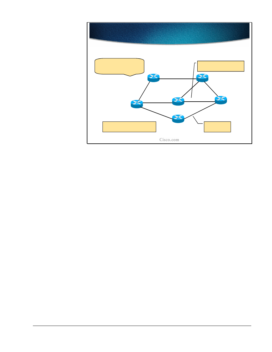
An example network is shown in the figure. Each link specifies a link cost for
metric calculation and a bandwidth available for reservation, such as a metric of
10 and an available bandwidth of 100Mbps for the link between R1 and R2. Other
than these criteria, no links are subject to any policy restriction disallowing their
use for creating Traffic Trunks.
The requirement is to create a Trunk from R1 to R6 with a bandwidth of 30Mbps.
Based simply on the link costs, the least cost path from R1 to R6 is R1-R4-R6
with a cost of 30. However the link from R4 to R6 has only 20Mbps of bandwidth
available for reservation and therefore cannot fulfill the requirements of the
Trunk.
Similarly, the link R5-R6 has only 20Mbps available so no paths can be allocated
via R5.
36
MPLS Traffic Engineering Technology
Copyright
2001, Cisco Systems, Inc.
© 2001, Cisco Systems, Inc.
MPLS Traffic Engineering Technology-41
Static and Dynamic Traffic
Engineering Tunnels
Static and Dynamic Traffic
Engineering Tunnels
R1
R2
R3
R6
R4
{20,50M}
{10,100M}
{10,100M}
{25,40M}
{10,100M}
Path has cost
of 45, not the
lowest cost.
Computed path for a dynamic
constraint-based Tunnel over the
least-cost path.
Administratively defined static
explicit path Tunnel is still possible
over any eligible path.
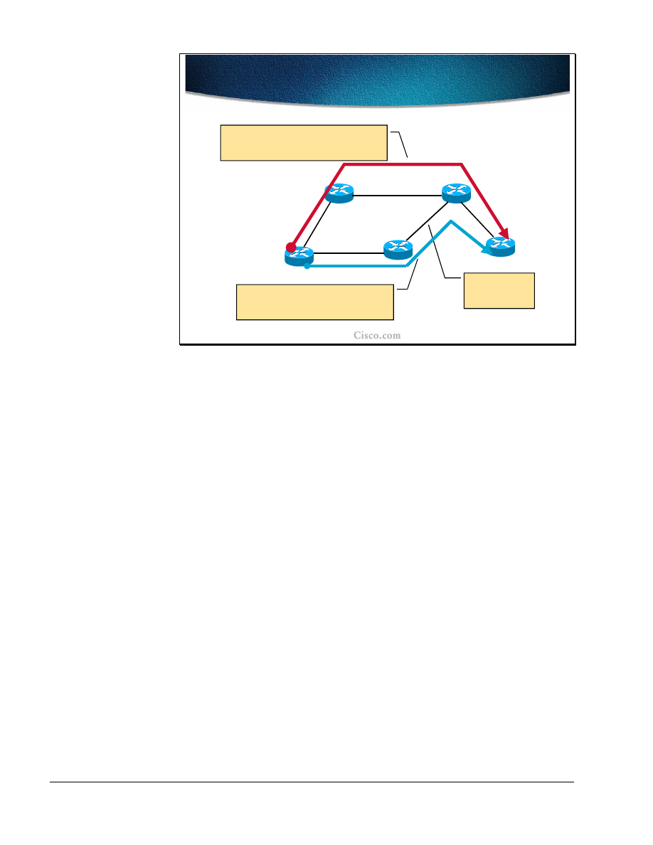
The diagram now shows only those links, which can satisfy the requirement for
30Mpbs of available bandwidth.
Over this topology, two Trunk paths are shown:
■
The path colored blue (R1-R4-R3-R6) has been defined statically by the
administrator. Had the administrator attempted to define a path that did not
have the required free bandwidth, the trunk establishment would have failed.
This trunk does indeed fulfill the minimum bandwidth requirement. However,
adding the link costs gives a total of 45, which is not the lowest cost possible.
■
The red (upper) path shows the result of a dynamic Constraint-Based path
calculation. The calculation has ignored any links which do not satisfy the
bandwidth requirement (those from the last diagram not shown in this
diagram, such as the connections to R5) and then run a Contrainted Shortest-
Path-First (CSPF) calculation on what remains. This calculation has yielded
the path R1-R2-R3-R6 with a path cost of 40.

Copyright
2001, Cisco Systems, Inc.
MPLS Traffic Engineering Technology
37
© 2001, Cisco Systems, Inc.
MPLS Traffic Engineering Technology-42
Path Setup with RSVP Signaling
Path Setup with RSVP Signaling
•
The next-hop routers are computed by the
Constraint-based routing algorithm
•
A signaling protocol is needed:
–
To establish and maintain Label Switched Paths
(LSP) for traffic trunks along an explicit path
–
For creating and maintaining resource reservation
states across a network (bandwidth allocation)
•
Constraint-based LSP (CB-LSP) is a path through an
MPLS network used by traffic trunk (MPLS-TE
tunnel)
•
LDP/TDP session is established across the trunk to
exchange labels for networks behind the trunk end-
point
The result of the Constraint-Based calculation is a list of routers, which form the
path to the destination. The path is a list of IP addresses identifying each next-hop
along the path.
However, this list of routers is known only to the router at the head-end of the
trunk attempting to build the tunnel. Somehow, this now explicit path must be
communicated to the intermediate routers. It is not up to the intermediate routers
to make their own Constrained SPF calculations: they merely abide by the path
provided to them by the head-end router. Therefore some signaling protocol is
required to confirm the path, check and apply the bandwidth reservations and
finally to apply the MPLS labels to form the MPLS Label-Switched-Path through
the routers. RSVP is used to confirm and reserve the path and LDP/TDP is used to
apply the labels.

38
MPLS Traffic Engineering Technology
Copyright
2001, Cisco Systems, Inc.
© 2001, Cisco Systems, Inc.
MPLS Traffic Engineering Technology-43
Resource ReSerVation Protocol
Resource ReSerVation Protocol
•
The Resource ReSerVation Protocol (RSVP) was
adopted by the IETF’s MPLS work group
•
RSVP message types:
–
RSVP Path message – source route reservation
requests carrying a sequence of IP interface
addresses calculated by CB-LSP
–
RSVP Reservation – to allocate labels and to
reserve resource
–
RSVP PathTear – to tear an old route
–
Two RSVP error messages when reservation is
rejected:
•
ResvErr and PathErr
The Resource reSerVation Protocol (RSVP) is specifically designed to allow
applications to reserve bandwidth in a network. Therefore it is an obvious
candidate to perform the path confirmation and reservation in MPLS Traffic
Engineering and has been adopted as such by the MPLS working group of the
IETF.
RSVP operates by using the following messages:
■
RSVP PATH message is used to trace the path through the network, checking
the resource availability at each stage and storing the path as it goes.
■
RSVP RESV (RESerVation) message is sent (by the far end router) in reply
to a PATH message to confirm the path and reserve the bandwidth on each
router in the path.
■
RSVP PATH_TEAR message tears down a reservation and releases the
bandwidth allocation so it can be used again.
■
During the PATH/RESV stage, the reservation could fail and lead to a
PATH_ERR or RESV_ERR message being generated.

Copyright
2001, Cisco Systems, Inc.
MPLS Traffic Engineering Technology
39
© 2001, Cisco Systems, Inc.
MPLS Traffic Engineering Technology-43
RSVP Decision Modules
RSVP Decision Modules
•
Two mechanisms are used when RSVP is to honor
reservation:
– Policy control
- determines whether the user has
administrative permission to make the reservation
– Admission control
- determines whether the node
has sufficient available resources to supply the
request
•
If either check fails, the RSVP program returns an
error notification to the router that originated the
request
Part of the process of RSVP is to confirm whether the reservation is acceptable at
each router along the path. This task is completed with the following checks:
■
Policy Control: Checks whether the initiator of the RSVP request has the
administrative privilege to make the reservation. This is more specific to
generic RSVP where a request may be made by a host system (typically a
multimedia application such as video or audio streaming). In the case of
MPLS Traffic Engineering, the request should be arriving from the head-end
router. .
■
Admission Control: Checks whether the resources are still available to satisfy
the reservation request. This is where the reason for the Constraint-Based path
calculation becomes clear. Because the available resources have, in effect,
been checked in advance (by the Constraint-Based path calculation), the
reservation should be successful on this count.
■
The reservation may not be successful due to the batched link-state
routing advertisements, Some resources that are being just reserved by
other traffic trunk might still be available to the router initiating a traffic
trunk request.
If either check fails then the reservation will be refused. A PATH_ERR would be
sent if the reservation failed while the PATH part of the process was in process
(because the request cannot be satisfied by one of the routers in the path). In
theory, as the PATH message checks that the resource is available to be reserved
on the way out, the RESV message should be accepted automatically on the way
back. However, situations can arise where the RESV is the part that fails, in
which case a RESV_ERR message is generated. A PATH_TEAR message
follows a PATH_ERR or RESV_ERR message to tear down any remaining parts
of the path.
40
MPLS Traffic Engineering Technology
Copyright
2001, Cisco Systems, Inc.
© 2001, Cisco Systems, Inc.
MPLS Traffic Engineering Technology-45
Assigning Labels to Physical
Links
Assigning Labels to Physical
Links
R1
R2
R3
R6
R4
IGP and LDP/TDP create labels for links based on the shortest path
determined by IGP. From R1 perspective, the best way to R6 is via
R2 – R3 link.
-----
Paths through R4 and R5 are not taken into account do to the
lack of available bandwidth.
LDP/TDP message
R5
R7
Pop
31
32
Implict-null (or Pop)
label for R6 loopbck.
34
37
Pop
{
cost
}
{20}
{
10
}
{10}
{25}
{20}
{10}
{10}
{25}
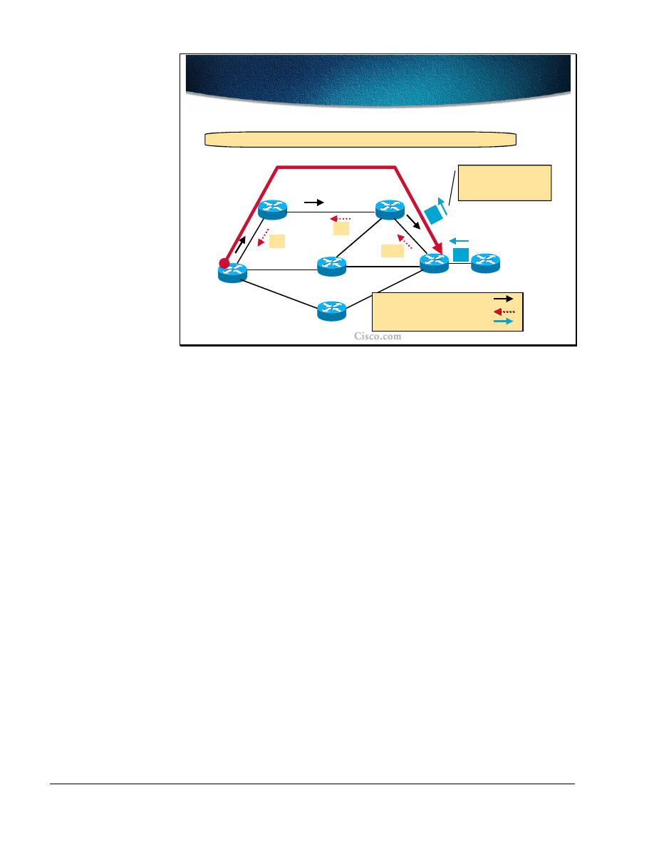
The diagram in the figure shows a sample network based on the earlier example.
This time, only the link costs (as per the IGP) are shown for each link.
The diagram shows the interaction between the IGP and the Label/Tag
Distribution Protocol. Using information from the IGP, LDP/TDP messages are
sent from R6 to R1, assigning labels as they go. At R1, the least-cost path and the
labels corresponding to that path are selected.
One interesting ‘label’ shown is ‘Pop’. ‘Pop’ signifies that the next router in the
path is the end of this particular MPLS Label-Switch Path and that the packet
should ‘pop’ back up from the MPLS layer to the routing layer.(‘Pop’ is a
programming term used to ‘pop’ items off a stack of stored items. Here it is used
to ‘pop’ one set of MPLS information off the MPLS label stack, and in this case
leaving no labels on the stack, therefore returning the packet to the routing layer)

Copyright
2001, Cisco Systems, Inc.
MPLS Traffic Engineering Technology
41
© 2001, Cisco Systems, Inc.
MPLS Traffic Engineering Technology-46
Assigning Labels to Traffic Trunk
Assigning Labels to Traffic Trunk
R1
R2
R3
R6
R4
RSVP allocates labels for the precomputed traffic trunk (R1-R2-R3-
R6) that is diverted from the least-cost path.
RSVP Path message
RSVP Reservation message
R5
R7
Pop
21
22
Implict-null RSVP
label for R6 loopbck.
RSVP works by sending out PATH messages to establish the path through the
network. In the case of MPLS Traffic Engineering, that path is included in the
RSVP Path message either by manually configuring an explicit path or by
dynamically calculating the path via CB-LSP. Therefore it is expected that the
PATH message will succeed in traversing the network without being rejected
along the way. While the RESV message returns along the path, it interacts with
MPLS to assign labels as it goes. Again, the last label in the path (the first label
allocated by the returning RESV message) is the implicit ‘Pop’ label to signify
this is the destination router for the MPLS-encapsulated packets.
Therefore, when the RSVP reservation is completed (the RESV message arrives
at the source router), the MPLS LSP is also completed.
42
MPLS Traffic Engineering Technology
Copyright
2001, Cisco Systems, Inc.
© 2001, Cisco Systems, Inc.
MPLS Traffic Engineering Technology-47
Assigning Labels for Destinations
behind the TT
Assigning Labels for Destinations
behind the TT
44
4
6
R1
R2
R3
R6
R7
Pop
21
22
Directed LDP/TDP hellos are used to find non-adjacent neighbors.
LDP/TDP labels 44
and 46 assigned to
R7 customer route.
RSVP Path message
RSVP Reservation message
LDP/TDP message
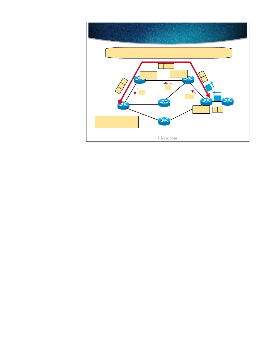
A new item in this network diagram are routes coming from R7. This router
could be a customer router attached to the ISP network (R1 to R6).
It would be possible to route packets through MPLS up to R6, ‘pop’ them back
into the IP layer and then route normally into the customer network. However, it
makes sense to try to keep the packet inside the level-2-switched MPLS layer.
In order to achieve this, further LDP/TDP hello messages are sent explicitly along
the path out of the end of the Traffic Trunk (R6) and into the customer network
(R7). These hellos create extra MPLS labels for the last part of the path defining
the route into the customer network inside MPLS. A label stack (of two labels)
will be required to reach the customer network from the R1 router.
Copyright
2001, Cisco Systems, Inc.
MPLS Traffic Engineering Technology
43
© 2001, Cisco Systems, Inc.
MPLS Traffic Engineering Technology-48
Forwarding over CB-LSP Path
Forwarding over CB-LSP Path
44
4
6
R1
R7
Pop
21
22
FIB:
R7 customer route
!
!
!
!
46
,
22
R6 loopback
!
!
!
!
22
LFIB:
22
!
!
!
!
21
LFIB:
21
!
!
!
!
Pop
LFIB:
46
!
!
!
!
44
4
6
R
7
2
2
46
R7
21
4
6
R
7
44
R7
The MPLS packet destined for R7 carries a stack of labels: The first
one is for the trunk end point, the second one for the route.
R2
R3
To route into the customer network inside MPLS, a stack of labels is created:
■
The first, top-most label, of the label stack (label 22 at R1) defines the path
inside the ISP network (the RSVP LSP identified in the previous diagrams).
■
When this top-most label is ‘pop’ped off the label stack (at R3), another label
comes to the top of the label stack. . This second label identifies the label into
the customer router (label 46 at R1).
■
As the ‘pop’ happens at R3, the MPLS label (the second label) for the
customer route must be defined between R6 and R3. On R6 it may refer to
another MPLS label in the customer network (as in this case) or alternatively
be ‘pop’ped to arrive natively at R7 itself.
Traffic destined for R6 itself would have only the top-most label in the label stack
(label 22 at R1). ‘Pop’ping this label off the stack at R3 leaves an empty MPLS
label stack at R6 and therefore the packet reverts to the IP layer on the link ? R3-
R6, and arrives at R6 as an IP packet ready to be routed. .

44
MPLS Traffic Engineering Technology
Copyright
2001, Cisco Systems, Inc.
© 2001, Cisco Systems, Inc.
MPLS Traffic Engineering Technology-49
Forwarding Table Modifications
Forwarding Table Modifications
•
Traffic engineering requires explicit routing
capability
•
Two levels – MPLS and IP
–
MPLS LSP routing - list of hops for an LSP
–
IP routing - an entry in the IP forwarding
table pointing to a MPLS-TE tunnel
interface
In order to use the traffic engineered tunnels some modifications must be made to
the forwarding tables and to the mechanisms they are built with. Explicit routing
capability is required at the MPLS level and at the IP forwarding level as well:
■
The MPLS LSP routing requires the list of hops for an LSP (explicit path).
■
For IP routing, an entry in the IP forwarding table has to point to the MPLS-
TE tunnel interface. This tunnel follows the established MPLS LSP.

Copyright
2001, Cisco Systems, Inc.
MPLS Traffic Engineering Technology
45
© 2001, Cisco Systems, Inc.
MPLS Traffic Engineering Technology-50
MPLS as Forwarding Engine –
LSP Level
MPLS as Forwarding Engine –
LSP Level
• MPLS LSP routing
- At the LSP level a traffic trunk
from source to destination node is built
–
Static - explicit path setup
–
Dynamic - dynamic path setup
•
Traffic trunks are mapped to LSP by signaling
protocol (RSVP)
–
Label is tied to the MPLS-TE tunnel interface
–
After label allocation the tunnel interface is up but
cannot be seen in the IP routing table
For a traffic trunk, an LSP path must be built from the source to the destination
(from the traffic trunk head-end to its endpoint, tail-end). The LSP path can be:
■
Statically defined (manually defining a list of hops towards the destination)
■
Dynamically built (by using constraint-based path computations)
The traffic trunks are mapped to the LSP using the signaling protocol (RSVP).
With label allocation to the MPLS-TE tunnel interface at the head-end of the
trunk, the tunnel comes up but does not appear in the IP routing table. The traffic
engineered tunnel itself does not appear in SPF calculations for the destinations
behind the trunk tail-end.

46
MPLS Traffic Engineering Technology
Copyright
2001, Cisco Systems, Inc.
© 2001, Cisco Systems, Inc.
MPLS Traffic Engineering Technology-51
MPLS as Forwarding Engine – IP
Level
MPLS as Forwarding Engine – IP
Level
• IP routing
is on top of LSP routing and does not see
internal details of the LSP
•
The traffic has to be mapped to the tunnel
– Static routing
- the static route in the IP routing
table points to an LSP tunnel interface
– Policy routing
- the next-hop interface is an LSP
tunnel
– Autoroute
- SPF enhancement
•
The head-end sees the tunnel as a directly
connected interface (for modified SPF only)
•
The cost of a tunnel is equal to the shortest IGP
metric regardless of the used path
The tunnel normally does not appear in IP routing table.The IP routing process
does not see the tunnel so the tunnel is normally not included in any SPF
calculations. The IP traffic can be mapped onto a tunnel in three different ways:
■
Using static routes that point to the tunnel interfaces.
■
Using policy based routing and set the next hop for the destination to the
tunnel interface.
■
Using the autoroute feature, which is an SPF enhancement that includes the
tunnel interface into the route calculation as well. The result of the autoroute
feature is that the tunnel is seen at the head-end (and only there) as a directly
connected interface. The metric (cost) of the tunnel is set to the normal IGP
metric from the tunnel head-end to the tunnel end-point (over the least cost
path, regardless if the tunnel is actually using the least cost path or not).
Note
With the autoroute feature, the traffic engineered tunnel appears in the IP routing
table as well but this appearance is restricted to the tunnel head-end only.
The first two options are not very flexible or scalable. The traffic for each
destination that needs to use the tunnel must be manually mapped to the tunnel.
For example, when using static routes, the tunnel is used only for the explicit
static routes. Any other traffics not covered by the explicit static routes, including
traffic for the tail-end router (even though the tunnel terminates
on it) will not be able to use the tunnel, instead, it will follow the normal IGP
path.

Copyright
2001, Cisco Systems, Inc.
MPLS Traffic Engineering Technology
47
Note
The autoroute feature is explained in details in Assigning Traffic to Traffic Trunks
lesson.

48
MPLS Traffic Engineering Technology
Copyright
2001, Cisco Systems, Inc.
© 2001, Cisco Systems, Inc.
MPLS Traffic Engineering Technology-52
Summary of MPLS-TE
Mechanisms
Summary of MPLS-TE
Mechanisms
•
IOS MPLS-TE tunnel interface (Traffic Trunk)
–
Configured with a set of resource requirements,
such as bandwidth and priority
•
MPLS-TE Constrained-based Path Calculation
Module
–
It determines a path the trunk should take, using a
link-state database containing flooded topology
and resource information
•
Link-state Protocol with TE extensions (IS-IS or
OSPF)
–
To globally flood topology and resource
information
–
Enhanced SPF algorithm
Overall, the MPLS-TE mechanisms include several components that interact in a
complex yet effective way to provide the engineered tunnels across the MPLS
enabled networks.
The main component of MPLS-TE is the MPLS-TE tunnel interface itself
which is the Traffic Trunk (TT), and which is configured with a set of resource
requirements including the required bandwidth and priority.
The Constraint-based Path Calculation determines the path (Label Switched
Path, LSP) the trunk should take using the link-state database that contains the
resource information. The resource information is flooded throughout the network
with modified link-state Interior Gateway Protocols (IGP) that include resource
information in their link-state updates. There are two routing protocols with TE
extensions: Integrated IS-IS and OSPF. The SPF algorithm is modified as well to
take into account the resource information when calculating the LSP path.

Copyright
2001, Cisco Systems, Inc.
MPLS Traffic Engineering Technology
49
© 2001, Cisco Systems, Inc.
MPLS Traffic Engineering Technology-53
Summary of MPLS-TE
Mechanisms (Cont.)
Summary of MPLS-TE
Mechanisms (Cont.)
•
Resource Reservation Protocol (RSVP) with
TE extensions
–
As a mechanism for establishing and
maintaining Label Switched Paths
•
Trunk Admission Control
–
Decides which trunks may use local (link)
resources
•
MPLS forwarding mechanism
The computed LSP path must be established using a signaling protocol. The
Resource reSerVation Protocol (RSVP) with TE extensions is used:
■
To reserve the required bandwidth.
■
To establish and maintain the MPLS labels for the LSP.
The bandwidth reservation is done via the Trunk Admission Control that decides
which trunks may use link resources if available.
After the LSP path is established and MPLS labels allocated, the MPLS
forwarding mechanism ensures that the traffic mapped onto the tunnel is
forwarded along the LSP path.

50
MPLS Traffic Engineering Technology
Copyright
2001, Cisco Systems, Inc.
Summary
After completing this lesson, you should be able to perform the following tasks:
■
List the components of MPLS traffic engineering
■
Explain the tunnel and link attributes
■
Describe the constraint-based path computation
■
Describe the role of RSVP in path setup procedures
■
Describe the forwarding table modification mechanisms
Lesson Review
1. What are the characteristics of a traffic trunk?
2. What modifications are needed to the IGP to support MPLS-TE?
3. What is a result of a Constraint-based path calculation?
4. Explain the role of RSVP in MPLS-TE.
5. How is traffic mapped to the MPLS-TE tunnel?

Copyright
2001, Cisco Systems, Inc.
MPLS Traffic Engineering Technology
51
Constraint-based Path Computation
Objectives
Upon completion of this lesson, you will be able to perform the following tasks:
■
Describe the detailed structure of MPLS-TE link attributes
■
Explain the role and usability of a guaranteed-bandwidth sub-pool
■
Describe the usability of affinity bits
■
Implement MPLS TE constraints with affinity bits
■
Describe the propagation of link attributes through an Interior Routing
Protocol (OSPF or IS-IS)
■
Describe the constraint-based path computation algorithm
■
Describe the interaction between link attributes and trunk attributes during the
constraint-based path computation

52
MPLS Traffic Engineering Technology
Copyright
2001, Cisco Systems, Inc.
© 2001, Cisco Systems, Inc.
MPLS Traffic Engineering Technology-58
MPLS-TE Link Resource
Attributes
MPLS-TE Link Resource
Attributes
•
Maximum Allocation Multiplier
–
Max. Bandwidth
•
The maximum bandwidth that can be
used on this link in this direction
–
Max. Reservable Bandwidth
•
The maximum amount of bandwidth that
can be reserved in this direction on this
link
–
Unreserved Bandwidth in this direction
(per priority 0-7)
The Constraint-based path computation that takes place at the head-end of the
traffic engineered tunnel must be provided with several resource attributes before
the LSP path is actually determined. These attributes include:
■
Link Resource Attributes that provide information on each link’s resources.
■
Traffic Trunk Attributes that characterize the Traffic Trunk.
Among Link Resource Attributes, the most important is the Maximum
Allocation Multiplier. This attribute deals with the amount of bandwidth
available on the specified link. ‘Available’ means ‘not already allocated’ rather
than ‘presently in use’ and is a measure of allocation not utilization. Furthermore,
because there are priority levels for Traffic Trunks, this availability information
needs to be configured for each priority level on the link. Normally, the
bandwidthat the upper priority level is always higher than at lower levels (0-7
levels). Due to over-subscriptions the total amount of bandwidth can exceed the
actual bandwidth of the link. There are three components of this attribute:
■
Max. Bandwidth provides information on the maximum bandwidth that can
be used on the link, per direction, since the traffic trunks are unidirectional.
This parameter is usually set to the configured bandwidth of the link.
■
Max. Reservable Bandwidth provides information on the maximum
bandwidth that can be reserved on the link per direction. By default it is set to
75% of the Max. bandwidth.
■
Unreserved Bandwidth provides information on the remaining bandwidth that
has not yet been reserved.
Note
Higher priority can preempt lower priority but lower priority can’t preempt higher
priority.

Copyright
2001, Cisco Systems, Inc.
MPLS Traffic Engineering Technology
53
© 2001, Cisco Systems, Inc.
MPLS Traffic Engineering Technology-59
Link Resource Attributes (Cont.)
Link Resource Attributes (Cont.)
•
Link Resource Class
–
Link is characterized by a 32-bit resource-class
attribute string
–
Associated with a traffic trunk in order to include
or exclude certain links from the path of the traffic
trunk
•
Constraint-based Specific Link Metric
–
This metric is administratively assigned to present
a differently weighted topology to traffic
engineering SPF calculations
•
Administrative weight (TE metric)
For each link, another Link Resource Attribute, the Link Resource Class, is
provided as well. The link is characterized by a 32-bit link resource-class attribute
string, which is matched with traffic trunk Resource Class Affinity attribute and
allows inclusion or exclusion of the link into or from the path for the trunk.
Each link has a cost or metric for calculating routes in the normal operation of the
IGP. It may be that, when calculating paths for Traffic Trunks, the link should use
a different metric than the IGP metric. Hence a ‘Constraint-Based Specific
Metric’ , the administrative weight, may be administratively assigned as well.

54
MPLS Traffic Engineering Technology
Copyright
2001, Cisco Systems, Inc.
© 2001, Cisco Systems, Inc.
MPLS Traffic Engineering Technology-60
MPLS-TE Trunk Attributes
MPLS-TE Trunk Attributes
•
Traffic Parameter
–
Indicates the resource requirements (e.g.
bandwidth) of the traffic trunk
•
Generic Path Selection and Management
–
Specifies how the path for the trunk is computed:
•
Static LSP - administratively specified via an off-
line central server
•
Constrained-based computed paths are based
on a combination of bandwidth and policies
The Traffic Trunk (TT) is characterized by several attributes that affect the path
setup and maintenance:
■
Traffic Parameter (Bandwidth) attributes specify (among other traffic
characteristics) the amount of bandwidth required by the Traffic Trunk. The
traffic characteristics may include peak rates, average rates, permissible burst
size, etc. From a traffic engineering perspective, the traffic parameters are
significant because they indicate the resource requirements of the traffic
trunk. These characteristics are useful for resource allocation.
■
Path Selection and Management attributes (Path Selection Policy) specifies
the way in which the head-end routers should select explicit paths for traffic
trunks. The path can be configured manually or computed dynamically using
the Constraint-based path computation, both taking the resource information
and policies into account.

Copyright
2001, Cisco Systems, Inc.
MPLS Traffic Engineering Technology
55
© 2001, Cisco Systems, Inc.
MPLS Traffic Engineering Technology-61
Trunk Attributes (Cont.)
Trunk Attributes (Cont.)
•
Trunk Resource Class Affinity
–
The properties the tunnel requires from internal
links
•
32-bit resource-class affinity bit string + 32-bit
resource-class mask
–
Link is included in the CB-LSP path when the
Trunk Resource Affinity string/mask matches the
Link Resource Class attribute
•
Adaptability
–
If re-optimization is enabled, then a traffic trunk
can be rerouted through different paths by the
underlying protocols
•
Primarily due to changes in resource availability
Additional trunk attributes that play a role in LSP path computation and
maintenance are:
■
The Resource Class Affinity attribute allows the network operator to apply
path selection policies by administratively including or excluding network
links. Each link may be assigned a Resource Class attribute. Resource Class
Affinity specifies whether to explicitly include or exclude links with resource
classes in the path selection process. The Resource Class Affinity is a 32-bit
string accompanied by a 32-bit resource-class mask. The mask indicates
which bits in the resource class need to be inspected. The link is included in
the Constraint-based LSP when the Resource Class Affinity string or mask
matches the Resource Class attributes.
■
The Adaptability attribute indicates whether the traffic trunk should be re-
optimized and consequently rerouted to another path primarily due to the
changes in resource availability.

56
MPLS Traffic Engineering Technology
Copyright
2001, Cisco Systems, Inc.
© 2001, Cisco Systems, Inc.
MPLS Traffic Engineering Technology-65
Trunk Attributes (Cont.)
Trunk Attributes (Cont.)
•
Priority
–
Relative importance of traffic trunks
–
Determines the order in which path selection is
done for traffic trunks at connection establishment
and under fault scenarios
• setup priority:
priority for taking a resource
•
Preemption
–
Determines whether another traffic trunk can
preempt a specific traffic trunk
• hold priority:
priority for holding a resource
Continuing with the Trunk Attributes the following two are closely associated and
play an important role in competitive situations where more traffic trunks compete
for the link resources. Two types of priorities are assigned to each traffic trunk:
■
Setup priority (Priority) defines the relative importance of traffic trunks and
determines the order in which path selection is done for traffic trunks at
connection establishment and during rerouting due to faulty conditions.
Priorities are also important at implementation, permitting pre-emption
because they can be used to impose a partial order on the set of traffic trunks
according to which pre-emptive policies can be actualized.
Holding priority (Pre-emption) defines the pre-emptive rights of
competing trunks and specifies the priority for holding a resource. The
attribute determines whether a traffic trunk can preempt another traffic
trunk from a given path, and whether another traffic trunk can preempt a
specific traffic trunk. Pre-emption can be used to assure that high priority
traffic trunks can always be routed through relatively favorable paths
within a differentiated services environment. Pre-emption can also be
used to implement various prioritized restoration policies following fault
events.

Copyright
2001, Cisco Systems, Inc.
MPLS Traffic Engineering Technology
57
© 2001, Cisco Systems, Inc.
MPLS Traffic Engineering Technology-63
Trunk Attributes (Cont.)
Trunk Attributes (Cont.)
•
Resilience
–
Determines the behavior of a traffic trunk under
fault conditions:
•
Do not reroute the traffic trunk
•
Reroute through a feasible path with enough
resources
•
Reroute through any available path regardless
of resource constraints
•
Policing
–
Determines the actions when a traffic trunk
becomes non-compliant
•
Indicates whether a non-conformant traffic trunk
is to be rate limited, tagged, or simply forwarded
Two additional Trunk attributes define the behavior of the tunnel in faulty
conditions or in cases when the trunk becomes non-compliant with trunk
attributes (e.g. required bandwidth):
■
The resilience attribute determines the behavior of the trunk under faulty
conditions and can specify:
–
Not to reroute the traffic trunk at all.
–
To reroute the trunk trough a path that can provide the required
resources.
–
To reroute the trunk though any available path irrespective of
available link resources.
■
The policing attribute determines the action in situations where the trunk
becomes non-compliant. Non-compliance is understood to be when the
amount of traffic on the trunk exceeds the required (reserved) bandwidth.
Three actions can be performed:
–
The traffic on the tunnel is rate limited (excessive traffic is dropped).
–
The excessive traffic is tagged but still forwarded.
–
The traffic is unconditionally forwarded.

58
MPLS Traffic Engineering Technology
Copyright
2001, Cisco Systems, Inc.
© 2001, Cisco Systems, Inc.
MPLS Traffic Engineering Technology-67
Implementing TE Policies with
Affinity Bits
Implementing TE Policies with
Affinity Bits
•
Trunk is characterized by:
–
32-bit trunk resource class affinity bit
string - default value of bits is 0
–
32-bit trunk resource class mask (0=do not
care, 1=care) - default value of the tunnel
mask = 0x0000FFFF
•
Link is characterized by a 32-bit link resource
class string – default value of bits is 0
The policies during the LSP path computation can be implemented using the
resource class affinity bits of the traffic trunk and the resource class bits of the
links over which the trunk should pass (following the computed LSP path).
Each traffic trunk is characterized by a 32-bit resource class affinity string
accompanied by a respective resource class mask. The zero bits in the mask
exclude the respective link resource class bits from being checked.
Each link is characterized by its resource class 32-bit string, which is set to 0 by
default. The matching of the tunnel trunk resource class affinity string with the
resource class string of the link is performed during the LSP path computation.
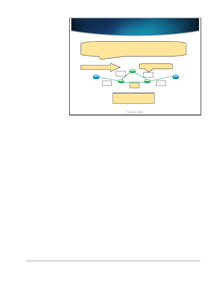
Copyright
2001, Cisco Systems, Inc.
MPLS Traffic Engineering Technology
59
© 2001, Cisco Systems, Inc.
MPLS Traffic Engineering Technology-65
Example: Using Affinity Bits to
Avoid Specific Links
Example: Using Affinity Bits to
Avoid Specific Links
A
B
0000
0000
0000
00
1
0
0000
C
D
E
Trunk A to B:
Only ADCEB is possible.
Traffic Trunk A to B
Setting a link bit in the lower half drives all tunnels off the link,
except those specially configured.
Trunk Affinity: bits =
0000
, mask =
0011
Link Resource Class
The example in the figure shows a sample network with the trunk resource class
affinity bits and link resource bits. For simplicity only the four bits (of the 32-bit
string) are shown. The trunk should be established between routers A (head-end)
and B (tail-end).
With the trunk resource class affinity bits and the link resource class bits at their
default values of 0, the Constraint-based path computation would have two
possible paths: A-D-E-B or A-D-C-E-B.
Because it is desirable to move all dynamically computed paths away from the
link D-E, the link resource class bits were set to a value 0010 and the trunk mask
was set to 0011.
In the example, the trunk mask requires that only the lower two bits require
matching. The 00 of the traffic affinity does not match the 10 of the link D-E
resource class and results in the exclusion of this link as a possible path for the
trunk. The only remaining alternative path is D-C-E, on which the default values
of the resource class string (all zeros) match the trunk affinity bits.

60
MPLS Traffic Engineering Technology
Copyright
2001, Cisco Systems, Inc.
© 2001, Cisco Systems, Inc.
MPLS Traffic Engineering Technology-69
Using the Affinity Bit Mask to
Allow all Links
Using the Affinity Bit Mask to
Allow all Links
A
B
0000
0000
0000
00
1
0
0000
C
D
E
Trunk A to B:
Again, ADEB and ADCEB are possible.
Traffic Trunk A to B
A specific tunnel can then be configured to allow all links by clearing
the bit in its affinity attribute mask.
Trunk Affinity: bits =
0000
, mask =
0001
Link Resource Class
Continuing with the sample network, only the lower bit was set in the trunk mask.
The trunk affinity bits remain unchanged as well as the resource class bits on the
D-E link.
The matching between the trunk resource class affinity bits and the link resource
class bits is done on the lowest bit only (due to the mask setting of 0001). The 0
of the trunk affinity bit (the lowest bit) matches with the 0 of the link resource
class bit (the lowest bit) and therefore the link D-E remains in the possible path
computation (along with the D-C-E link).
Which path will actually be used depends on other trunk and link attributes,
including the required and available bandwidth.
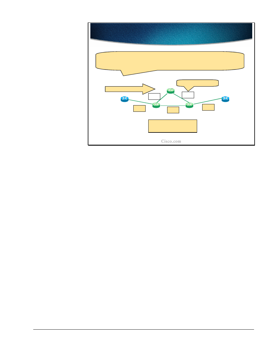
Copyright
2001, Cisco Systems, Inc.
MPLS Traffic Engineering Technology
61
© 2001, Cisco Systems, Inc.
MPLS Traffic Engineering Technology-70
Example: Using Affinity Bits to
Dedicate Links to Specific Purposes
Example: Using Affinity Bits to
Dedicate Links to Specific Purposes
A
B
00
1
0
0000
0000
00
1
0
00
1
0
C
D
E
Trunk A to B:
ADEB is possible
.
Traffic Trunk A to B
A specific tunnel can be restricted to only some links by turning on
the bit in its affinity attribute bits.
Trunk Affinity: bits =
0010
, mask =
0011
Link Resource Class
The last example with the sample network deals with setting the trunk resource
class affinity bits and the link resource class bits to force the tunnel to follow a
specific path. Links A-D-E-B are all configured with the resource class value
0010. The trunk resource class affinity bits are set to a value 0010 and the mask to
0011. Only the lower two bits will be compared in the Constraint-based path
computation. The 10 of the trunk resource class affinity matches the 10 of the link
resource class on all links configured with that value. The 10 does not match the
00 set on the path D-C-E and thus the only possible LSP path remains (A-D-E-B).

62
MPLS Traffic Engineering Technology
Copyright
2001, Cisco Systems, Inc.
© 2001, Cisco Systems, Inc.
MPLS Traffic Engineering Technology-71
Propagating Link Attributes with
Link-state Routing Protocol
Propagating Link Attributes with
Link-state Routing Protocol
•
For Link Resource propagation the flooding
service from the Link-State IGP is reused
–
Opaque LSA for OSPF - draft-katz-yeung-
ospf-traffic-01.txt
–
New wide TLV for IS-IS - draft-ietf-isis-
traffic-01.txt
The link resource attributes must be propagated throughout the network to be
available at the head-end of the traffic trunk when the LSP path computation takes
place.
Since the propagation (flooding) of the attributes can only be achieved by link-
state routing protocols (Interior Gateway Protocols), OSPF and IS-IS were
extended to support the MPLS-TE features.
The OSPF uses new Link State Advertisements (Opaque LSA) and IS-IS uses new
Type-Length-Value attributes in its Link State Packets (LSP).
The details on OSPF and ISIS extensions for MPLS-TE can be found in the
following documents:
■
Opaque LSA (type 10) for OSPF, draft-katz-yeung-ospf-traffic-01.txt, IETF
■
New wide TLV (type 22) for IS-IS, draft-ietf-isis-traffic-01.txt, IETF
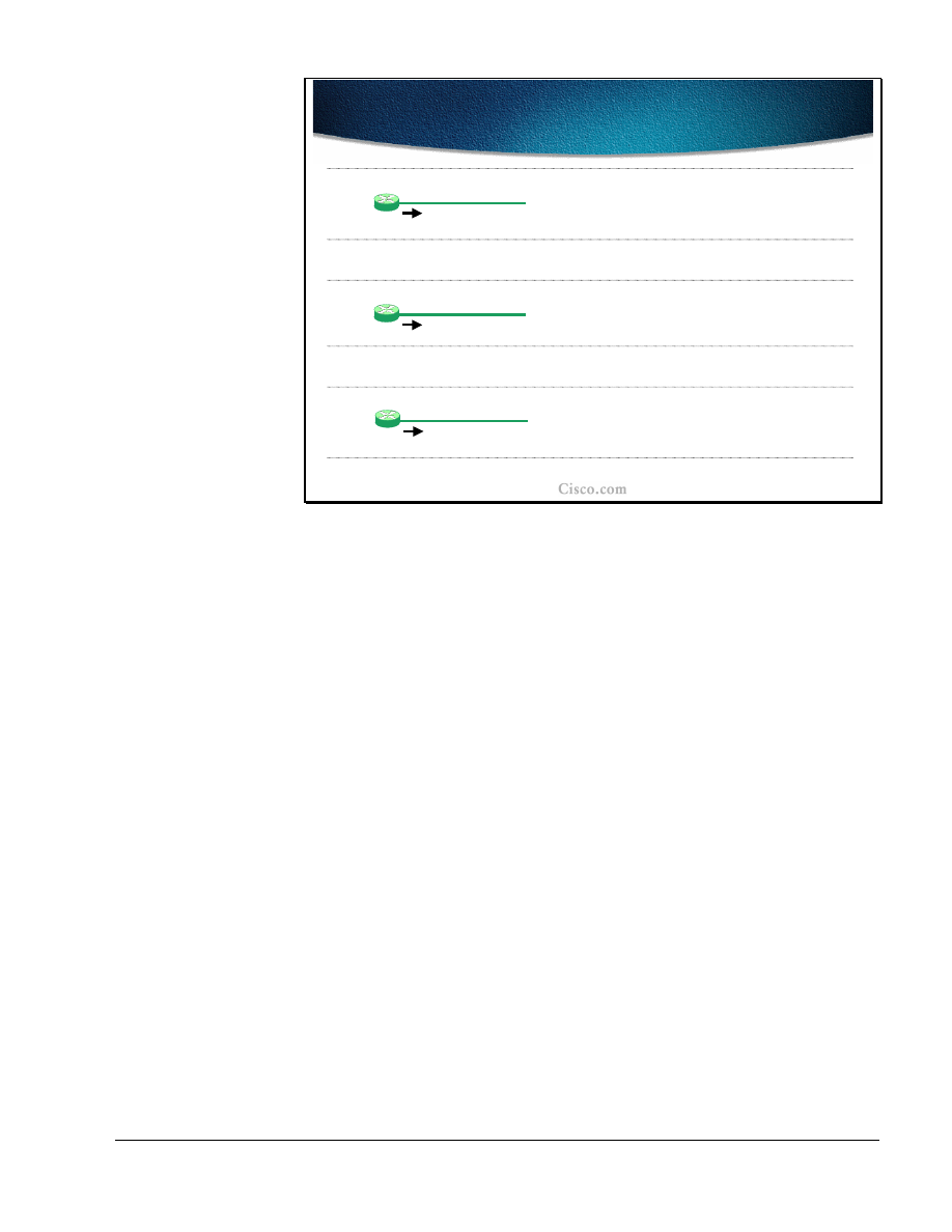
Copyright
2001, Cisco Systems, Inc.
MPLS Traffic Engineering Technology
63
© 2001, Cisco Systems, Inc.
MPLS Traffic Engineering Technology-69
Per-Priority Available Bandwidth
Per-Priority Available Bandwidth
D
Link L, BW=100
D advertises: AB(0)=100=…= AB(7)=100
AB(i) = ‘Available Bandwidth at priority i”
D
Link L, BW=100
D advertises: AB(0)=AB(1)=AB(2)=100
AB(3)=AB(4)=…=AB(7)=70
Setup of a tunnel over L at priority=3 for 30 units
D
Link L, BW=100
D advertises: AB(0)=AB(1)=AB(2)=100
AB(3)=AB(4)=70
AB(5)=AB(6)=AB(7)=40
Setup of an additional tunnel over L at priority=5 for 30
units
Another important factor in the LSP path computation is the available bandwidth
on the link that the traffic trunk will pass. These bandwidths are configured per
priority level (8 levels, 0 being the highest, 7 the lowest) and communicated in
respective IGP link-state updates, again per priority.
When a certain amount of the bandwidth is reserved at a certain priority level, this
amount is subtracted from the available bandwidth at that level and at all levels
below. The bandwidth at upper levels remains unchanged.
In the example, (isn’t the AB a calculated value which has no default?) the max.
bandwidth is set to the bandwidth of the link, which in the example is 100. The
available bandwidth (AB) is advertised in the link-state packets of the router D
and the value is 100 at all priority levels before any tunnel is setup.After that a
tunnel at priority level 3 requiring 30 units of bandwidth is set up across the link
L. The available bandwidth at all priority levels above (0, 1 and 2) remains
unchanged at 100. On all other levels, 30 was subtracted from 100 which resulted
in available bandwidth of 70 on priority level 3 and below (4-7).
Another tunnel is set up at priority level 5 requiring 30 units of bandwidth across
the link L. The available bandwidth at all priority levels above remains unchanged
with 100 on 0 to 2 and 70 on 3 and 4. On all other levels 30 was subtracted from
70, which resulted in an available bandwidth of 40 on priority level 5 and below
(6-7).

64
MPLS Traffic Engineering Technology
Copyright
2001, Cisco Systems, Inc.
© 2001, Cisco Systems, Inc.
MPLS Traffic Engineering Technology-70
Flooding Resource Attributes
Flooding Resource Attributes
•
IGP resource flooding takes places when:
–
Link-state changes
–
Resource class of a link changes
•
Manual reconfiguration
•
Amount of available bandwidth crosses one of
the pre-configured thresholds
–
Periodic (timer based)
•
A node check attributes if different it floods its
update status
–
On LSP setup failure
The flooding of resource attributes by the IGP takes place at certain conditions
and events:
■
When the link changes its state (up, down).
■
When the resource class of the link changes due to a manual reconfiguration
or in case some pre-configured thresholds are crossed by the available
bandwidth.
■
Periodically (based on a timer), the node checks resource attributes and if they
if the resource attributes were changed, the update is flooded.
■
When the LSP path setup fails.
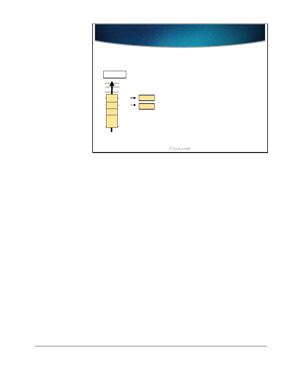
Copyright
2001, Cisco Systems, Inc.
MPLS Traffic Engineering Technology
65
© 2001, Cisco Systems, Inc.
MPLS Traffic Engineering Technology-71
Significant Change and Pre-
configured Thresholds
Significant Change and Pre-
configured Thresholds
•
For stability reasons rapid changes should not
cause rapid generation of updates
–
Each time a threshold is crossed, an
update is sent (different thresholds for
Up and Down)
50%
100%
70%
85%
92%
Tresholds
Update
Update
•
It is possible that the head-end node thinks
it can signal an LSP tunnel via node X while
X does not have the required resources
–
X refuses the LSP tunnel, and broadcasts an
update of its status
For stability purposes the significant rapid changes in available link resources
should not trigger the updates immediately. The drawback of not propagating the
change immediately is that in some cases the head-end sees the link as available
for the LSP path and includes the link in its path computation even though the
link may be down or does not have the required resource available. When the LSP
path is actually being established, a node with the link lacking the required
resources cannot establish the path and floods an immediate update to the
network.
The thresholds for resources are set both for an up direction (resources exceeding
the threshold) and a down direction (resources dropping below the threshold).
When the threshold is crossed (in either direction) the node generates an update
carrying the new resource information.
The graphic shows the threshold values for up direction (100%, 92%, 85%, 70%
and 50%) and two updates being sent out immediately when the margin is
crossed.

66
MPLS Traffic Engineering Technology
Copyright
2001, Cisco Systems, Inc.
© 2001, Cisco Systems, Inc.
MPLS Traffic Engineering Technology-75
Constraint-based Path
Computation
Constraint-based Path
Computation
•
When establishing a trunk, the edge routers have
knowledge of both network topology and link
resources
–
Two methods for establishing traffic trunks
•
Static and dynamic path setup
–
In both cases the result is an explicit route
expressed as a sequence of numbered IP interface
addresses of links in the path from trunk end-
points
–
RSVP is used to establish and maintain
Constraint-based Label Switched Paths for traffic
trunks along an explicit path
The head-end of the traffic trunk has the visibility both of the network topology
and network resources. This information is flooded throughout the network via a
link-state IGP.
The LSP path for the traffic trunk can be statically defined or computed
dynamically. The computation takes the available resources and other trunk and
link attributes into account (thus constraint-based path computation). The result of
the constraint-based path computation is a series of IP-addresses representing the
hops on the LSP path between the head-end and tail-end of the traffic trunk.
For LSP signaling and the final establishment of the path, the RSVP is used.

Copyright
2001, Cisco Systems, Inc.
MPLS Traffic Engineering Technology
67
© 2001, Cisco Systems, Inc.
MPLS Traffic Engineering Technology-73
Constraint-based Path
Computation (Cont.)
Constraint-based Path
Computation (Cont.)
•
Dynamic Constraint-based path computation is
triggered by the trunk’s head-end:
–
For a new trunk
–
For an existing trunk whose current LSP failed
–
For an existing trunk when doing re-optimization
•
CBR restrictions:
–
Restricted to a single OSPF or IS-IS area (full
visibility is mandatory)
–
Not considering the links which are explicitly
excluded or those with insufficient bandwidth
The Constraint-based path computation is always performed at the traffic trunk
head-end. The computation is triggered for:
■
A new trunk
■
An existing trunk whose Label Switched Path setup has failed
■
The re-optimization of an existing traffic trunk
The LSP path computation is restricted by several factors (constraint-based). The
LSP path can only be computed if:
■
The endpoints of the trunk are in the same OSPF or IS-IS area (due to link-
state flooding of resources).
■
The links that are explicitly excluded via the link resource class bit string, or
that cannot provide the required bandwidth, are pruned from the computation.

68
MPLS Traffic Engineering Technology
Copyright
2001, Cisco Systems, Inc.
© 2001, Cisco Systems, Inc.
MPLS Traffic Engineering Technology-74
Constraint-based Path Selection
Constraint-based Path Selection
•
Path selection
–
CBR uses its own metric (Admin. Weight or TE cost; by
default equal to the IGP cost) - used only during
constrained-based computation
–
In case of a tie select the path with:
•
The highest minimum bandwidth
•
The smallest hop-count
•
If everything else fails then pick a path at random
•
LSP path setup – an explicit path is used by RSVP to reserve
resources and establish LSP path
•
Final result:
Unidirectional MLPS-TE tunnel, seen only at
the
head-end router
The Constrained-based path computation selects the path that the traffic trunk will
take based on the administrative weight (TE cost) of each individual link. This
administrative weight is by default equal to the IGP link metric. The value is used
only during the constraint-based path computation.
If there are more candidates for the LSP path (several paths with the same metric)
then the selection criteria is (in sequential order):
■
The highest minimum bandwidth on the path takes precedence.
■
The smallest hop count takes precedence.
If after applying all the criteria still more than one path exists the path is randomly
chosen.
When the LSP path is computed, the RSVP is used to actually reserve the
bandwidth, to allocate labels for the path, and finally to establish the LSP path.
The result of a constraint-based path computation is a unidirectional MPLS-TE
tunnel (traffic trunk) that is seen only at the tunnel endpoints (head-end and tail-
end).

Copyright
2001, Cisco Systems, Inc.
MPLS Traffic Engineering Technology
69
© 2001, Cisco Systems, Inc.
MPLS Traffic Engineering Technology-75
MPLS-TE Tunnels
MPLS-TE Tunnels
•
MPLS-TE tunnel is no link for Link-state adjacency
–
Establishment of a tunnel does not trigger any
LSA announcements or a new SPF calculation
–
IOS uses tunnel interface for MPLS-TE tunnel
creation and visualization but behaviour of MPLS-
TE tunnels is fairly different from other tunnel
protocols (e.g., GRE)
•
Only traffic entering at head-end router will use
tunnel
• IP cost:
If autoroute used MPLS-TE tunnel in the IP
routing table has a cost of the shortest IGP path to
the tunnel destination (regardless of the LPS path)
From the perspective of an IGP routing, the traffic trunk (tunnel) is not seen as an
interface at all and is not included in any IGP route calculation (apart from other
IP tunnels like Generic Route Encapsulate tunnels). The traffic engineered tunnel,
when established, does not trigger any link-state update or any SPF calculation.
The Cisco IOS software uses the tunnel mainly for visualization. The rest of the
actions associated with the tunnel are done by the MPLS forwarding and other
MPLS-TE related mechanisms.
The IP traffic that will actually use the traffic engineered tunnel is forwarded to
the tunnel only by the head-end of the tunnel. In the rest of the network, the tunnel
is not seen at all (no link-state flooding).
With the autoroute feature, the traffic trunk (tunnel):
■
appears in the routing table
■
has an associated IP metric (cost equal to the best IGP metric to the tunnel
endpoint)
■
is also used to forward the traffic for destinations behind the tunnel endpoint
Even with the autoroute feature, the tunnel itself is not used in link-state updates
and the rest of the networks still does not have any knowledge of it.

70
MPLS Traffic Engineering Technology
Copyright
2001, Cisco Systems, Inc.
© 2001, Cisco Systems, Inc.
MPLS Traffic Engineering Technology-76
Example: Path Selection
Considering Policy Constraints
Example: Path Selection
Considering Policy Constraints
Tunnel’s request:
From R1 to R6; Priority 3, BW = 30 Mbps,
Resource Affinity: 0010, mask: 0011
R1
R2
R3
R6
R4
{Link Resource Class}
{0010}
R5
{0010}
{0010}
{0010}
{0010}
{0010}
{0010}
{00
11
}
Link R4-R3
is exluded.
The example of the constraint-based path computation and LSP path selection
requires that the traffic trunk (tunnel) be established between R1 (head-end) and
R6 (tail-end). The traffic trunk requirements are as follows:
■
The required bandwidth at priority level 3 is 30 Mbps
■
The resource class affinity bits are set to 0010 and the trunk’s mask is 0011.
The checking will be done only on the lower two bits.
The link R4-R3 should be excluded from the LSP path and its resource class bit
string is set to 0011 accordingly. When the traffic trunk resource class affinity bits
are compared to the link R4-R3 resource class bits, there is no match, and the link
is effectively excluded from the LSP path computation.
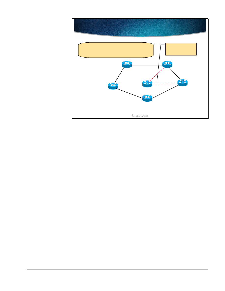
Copyright
2001, Cisco Systems, Inc.
MPLS Traffic Engineering Technology
71
© 2001, Cisco Systems, Inc.
MPLS Traffic Engineering Technology-77
Example: Path Selection
Considering Available Resources
Example: Path Selection
Considering Available Resources
Tunnel’s request:
From R1 to R6; Priority 3, BW = 30 Mbps,
Resource Affinity: 0010, mask: 0011
{cost,
priority
,
available BW
}
{20,3,50M}
{10,
3,
100M
}
{10,3,100M}
{20,3,
20M
}
{10,3,100M}
The least-cost path,
but not enough
bandwidth
{10,3,100M}
{30,3,50M}
R1
R2
R3
R6
R4
R5
The next parameter checked during the constraint-based path computation is the
TE cost (administrative weight) of each link through which the tunnel will
possibly pass. The lowest cost is calculated across the path R1-R4-R6 and the
overall cost is 30. All other possible paths have a higher overall cost.
When resources are take into account, the constraint-based path computation finds
that on the lowest-cost path there is not enough bandwidth to satisfy the traffic
trunk requirements (30 Mbps required, 20 Mbps available). As a result, the link
R4-R6 is effectively excluded from the LSP path computation.

72
MPLS Traffic Engineering Technology
Copyright
2001, Cisco Systems, Inc.
© 2001, Cisco Systems, Inc.
MPLS Traffic Engineering Technology-78
Example: Selecting the Best Path
Example: Selecting the Best Path
The head-end router has two possible paths with the total cost of
40: R1-R2-R3-R6 and R1-R5-R6, both offering at least 50 Mbps
(minimim BW). Due to the smaller hop-count R1-R5-R6 is
selected.
{20,3,50M}
{10,3,100M}
{10,3,100M}
{10,3,100M}
{30,3,50M}
R1
R2
R3
R6
R4
R5
{cost,
priority
,
available BW
}
{10,
3,
100M
}
The resulting LSP paths (after exclusion of the links that do not satisfy the traffic
trunk requirements) in the example are: R1-R2-R3-R6 and R1-R5-R6. Both paths
have a total cost of 40 and the tie has to be resolved using the tie-break rules.
First the highest minimum bandwidth on the path is compared. After the
comparison still both paths are candidates since both can provide at least 50 Mbps
of the bandwidth.
The next rule, the minimum number of the hops on the LSP path, is applied. .
Since the lower path (R1-R5-R6) has a lower hop-count, this path is finally
selected and the constraint-based computation is concluded.
The next step toward final establishment of the LSP path for the traffic
engineered tunnel is the signalization of the path via RSVP.

Copyright
2001, Cisco Systems, Inc.
MPLS Traffic Engineering Technology
73
© 2001, Cisco Systems, Inc.
MPLS Traffic Engineering Technology-64
Guaranteed-Bandwidth TE (GB-
TE)
Guaranteed-Bandwidth TE (GB-
TE)
• An extension of MPLS-TE (basically the
signaling feature)
•
Allows CBR of GB-TE Tunnels to use more
restrictive bandwidth constraints
•
DiffServ ensures that bandwidth for GB-TE
tunnels is set aside on each link in the
network
• Dual-Bandwidth Pool Traffic Engineering
Guaranteed Bandwidth Traffic Engineering (GB-TE) extends the current MPLS
Traffic Engineering capabilities to introduce the awareness of a particular Class
of Traffic, which is the Guaranteed Bandwidth traffic. GB-TE enables the Service
provider to perform a separate admission control and route computation of the
Guaranteed Bandwidth traffic. The GB-TE is another signaling feature of IGP and
RSVP.
With only a single bandwidth pool on the link in traditional MPLS-TE, when the
bandwidth is reserved for the tunnel, the traffic within a tunnel is considered as a
single class. For example, when voice and data are inter-mixed within the same
tunnel, the QoS mechanisms cannot ensure better service for the voice. Normally,
class-based weighted-fair queueing (CB-WFQ) can be performed for the tunnel.
The idea of GB-TE is to guarantee the bandwidth for GB-TE tunnels across the
network. For critical applications (e.g. voice), a separate GB-TE tunnel is created.
Thus two bandwith pools are used, one for traditional MPLS-TE tunnels and one
for GB-TE tunnels. The DiffServ Quality of Service mechanisms (low-latency
queueing (LLQ)) ensure that bandwidth for GB-TE tunnels is dedicated for these
tunnels.In the initial phase, the GB-TE supports a single Class of Guaranteed
Bandwidth. It is expected that subsequent phases of GB-TE will extend
capabilities such as the support of multiple Classes of Guaranteed Bandwidth and
the dynamic re-programming of queuing or scheduling mechanisms.

74
MPLS Traffic Engineering Technology
Copyright
2001, Cisco Systems, Inc.
© 2001, Cisco Systems, Inc.
MPLS Traffic Engineering Technology-65
GB-TE Extensions
GB-TE Extensions
•
MPLS-TE has the following extensions for GB-TE:
–
Two types of
bandwidth
limits per interface
–
IGP advertises both types of
bandwidth
–
Tunnel configured with appropriate
bandwidth
type
–
Appropriate
bandwidth
type considered in path
calculations
–
Tunnel signaled (via RSVP) with the appropriate
bandwidth
type
GB-TE tunnels are similar to regular TE tunnels. To support GB-TE, some
modifications to regular MPLS-TE mechanisms were done:
■
There are two types of bandwith per each link in the network (two bandwidth
pools – the global pool and the sub-pool).
■
These bandwidths are both announced in the link-state updates carrying
resource information.
■
The tunnel (traffic trunk) parameters include the bandwidth type the tunnel
will use.
■
The Constraint-based path calculation is done with respect to the type of the
bandwidth the tunnel requires.In RSVP messages, it is always indicated
whether the LSP to be set-up is a regular MPLS-TE tunnel or GB-TE tunnel..
■
Intermediate nodes perform admission control and bandwidth allocation
(“locking” for the GB-TE) on the appropriate bandwidth pool.
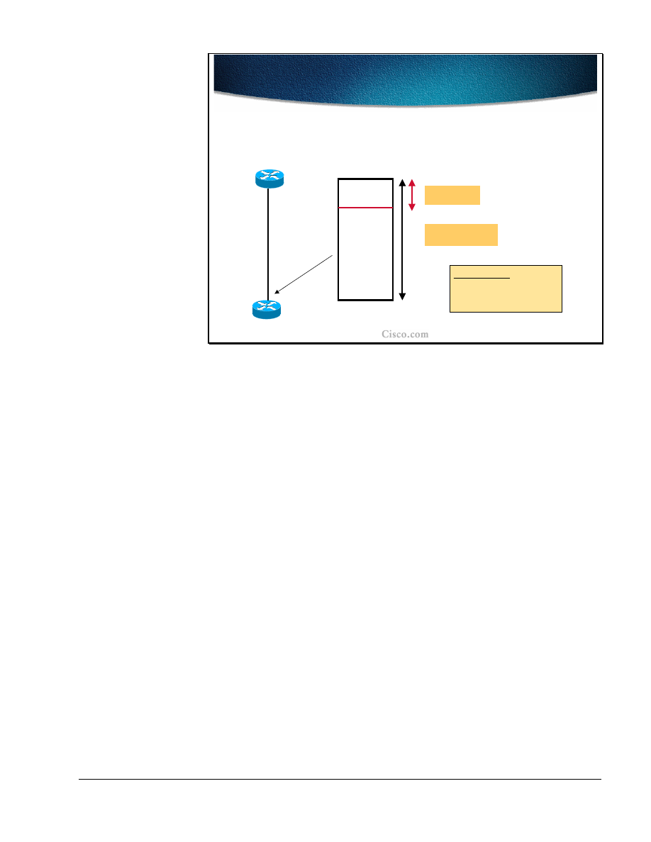
Copyright
2001, Cisco Systems, Inc.
MPLS Traffic Engineering Technology
75
© 2001, Cisco Systems, Inc.
MPLS Traffic Engineering Technology-66
GB-TE Dual-Bandwidth Pools
GB-TE Dual-Bandwidth Pools
• Global pool tracks the true available bandwidth
(takes into
account the bandwidth used by both types of tunnels)
• SubPool only keeps track of the constraint for the GB-TE
Physical BW = P
SUB-POOL maximum bw: Z
GLOBAL POOL maximum bw: X
Constraints:
• X, Z independent of P
• Z <= X
On each link in the network two bandwidth pools are established:
■
Global (main) pool that keeps track of the true available bandwidth. The pool
takes into account the bandwidth used by both of the tunnels.
■
Sub-pool (GB-TE) which tracks only the bandwidth for the GB-TE tunnels.
The bandwidths specified for both pools are independent of the actual physical
bandwidth of the link (providing for over-subscription). The same applies also to
the traditional MPLS-TE with one bandwidth pool.
The only constraint for the two pools is that the bandwidth of the sub-pool
(dedicated to GB-TE tunnels) must not exceed the bandwidth in the global pool.

76
MPLS Traffic Engineering Technology
Copyright
2001, Cisco Systems, Inc.
Summary
After completing this lesson, you should be able to perform the following tasks:
■
Describe the detailed structure of MPLS-TE link attributes
■
Explain the role and usability of a guaranteed-bandwidth sub-pool
■
Describe the usability of affinity bits
■
Implement MPLS TE constraints with affinity bits
■
Describe the propagation of link attributes through an Interior Routing
Protocol (OSPF or IS-IS)
■
Describe the constraint-based path computation algorithm
■
Describe the interaction between link attributes and trunk attributes during the
constraint-based path computation
Lesson Review
1. List the major MPLS-TE link attributes that influence the LSP path
computation.
2. List the major traffic trunk attributes that influence the LSP path computation.
3. How are link attributes known to the head-end of the traffic trunk?
4. How can a certain link be excluded from the LSP path computation?
5. Which path is selected when there are several equal-cost LSP path
candidates?

Copyright
2001, Cisco Systems, Inc.
MPLS Traffic Engineering Technology
77
Path Setup and Maintenance
Objectives
Upon completion of this lesson, you will be able to perform the following tasks:
■
Describe the MPLS-TE path setup procedures
■
Explain the details of RSVP assistance in MPLS TE path setup
■
Describe the functions of trunk and link admission control
■
Explain path monitoring and rerouting
■
List the methods for path and link protection
■
Explain the traffic trunk re-optimization and bandwidth requirement
adjustments

78
MPLS Traffic Engineering Technology
Copyright
2001, Cisco Systems, Inc.
© 2001, Cisco Systems, Inc.
MPLS Traffic Engineering Technology-86
LSP Path Setup
LSP Path Setup
•
LSP path setup is initiated at the head-end of a trunk
–
Explicit route (next-hop routers) is statically
defined or computed by CBR
•
Explicit route is used by RSVP to assign labels
and to reserve bandwidth on each link
–
MPLS downstream-on-demand label
allocation mode
–
Tunnel attributes that affect path setup:
•
Bandwidth, Priority and Affinity attributes
The Label Switched Path (LSP) setup is always initiated at the traffic trunk head-
end. The explicit route for the traffic trunk is composed of the list of next-hop
routers towards the trunk endpoint. The LSP tunnels can be statically defined or
computed with constraint-based routing and thus routed away from network
failures, congestion, and bottlenecks.
The explicit route is used by the Resource ReserVation protocol (RSVP) with
traffic engineering extensions to assign labels and to reserve the bandwidth on
each link. Labels are assigned using the downstream-on-demand allocation mode.
The path setup is affected by the following tunnel attributes:
■
Bandwidth
■
Priority
■
Affinity attributes
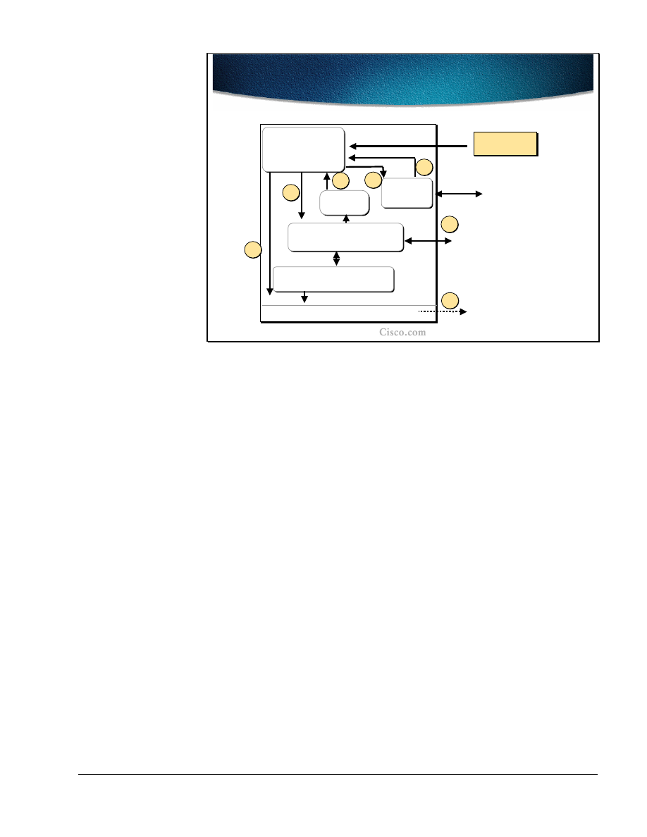
Copyright
2001, Cisco Systems, Inc.
MPLS Traffic Engineering Technology
79
© 2001, Cisco Systems, Inc.
MPLS Traffic Engineering Technology-88
Path Setup Steps
Path Setup Steps
Traffic
Engineering
Control
Path
Calculation
RSVP
IS-IS/OSPF
Routing
Routing Table/Label Forwarding
Tunnel
configuration
Tunnel
configuration
2
3
4
Signal
Setup
6
7
Topology + Resource
Attribute Database
IS-IS/OSPF link-state and
resource flooding
1
5
The figure represents a conceptual block diagram of the pieces that form the
constraint-based routing and path computation. In the upper left corner there is a
Traffic Engineering control module where the control algorithms run. The
module looks at the tunnels that have been configured for constraint-based
routing.
The Traffic Engineering control module will periodically check the constraint-
based routing topology database (shown in the middle of the block diagram) to
calculate the best current path from the current device to the tunnel destination.
Once the path is calculated, the module will pass the path off to the RSVP module
to signal the circuit setup across the network. If the signalization succeeds, the
signaling message will eventually return to the device, and RSVP will announce
back to Traffic Engineering control module that the tunnel has been established.
Consequently the Traffic Engineering control module will tell the IGP routing
module that the tunnel is available for use. The IGP routing module will include
the tunnel information into its routing table calculation and use it to affect what
routes are put into the routing table.

80
MPLS Traffic Engineering Technology
Copyright
2001, Cisco Systems, Inc.
© 2001, Cisco Systems, Inc.
MPLS Traffic Engineering Technology-88
RSVP Usage in Path Setup
RSVP Usage in Path Setup
•
RSVP makes resource reservations for both unicast
and multicast applications
–
Support for dynamic membership changes and
automatic adaptation to routing changes
–
Transports and maintains traffic control and policy
control parameters
–
RSVP sends periodic refresh messages to
maintain the state along the reserved path
–
RSVP sessions are used between routers, not
hosts
•
RSVP message types (Path, Resv, PathTear, ResvErr
and PathErr)
The RSVP plays a significant role in the path setup for LSP tunnels and supports
both unicast and multicast applications. The RSVP dynamically adapts to changes
either in membership (e.g. multicast groups) or in routing itself (changes in
routing tables). Additionally the RSVP transports the traffic parameters and
maintains the control and policy over the path. The maintenance is done by
periodic refresh messages sent along the path to maintain the state. In the normal
usage of RSVP, the sessions are run between hosts. In traffic-engineering, the
RSVP sessions are run between the routers on the tunnel endpoints. The following
RSVP message types are used in path setup:
■
Path
■
Resv
■
PathTear
■
ResvErr
■
PathErr

Copyright
2001, Cisco Systems, Inc.
MPLS Traffic Engineering Technology
81
© 2001, Cisco Systems, Inc.
MPLS Traffic Engineering Technology-90
RSVP Objects
RSVP Objects
•
Five objects are defined for Path and Resv
messages
Object Name
Object Name
Applicable RSVP Messages
Applicable RSVP Messages
LABEL_REQUEST
LABEL_REQUEST
LABEL
LABEL
EXPLICIT_ROUTE
EXPLICIT_ROUTE
RECORD_ROUTE
RECORD_ROUTE
Path
Path
SESSION_ATTRIBUTE
SESSION_ATTRIBUTE
Resv
Resv
Path
Path
Path, Resv
Path, Resv
Path
Path
In the Path and Resv messages of the RSVP there are five objects that are traffic
engineering related:
■
A Label_Request object is carried in the Path message and requests the label
assignment. A request to bind labels to a specific LSP tunnel is initiated by an
ingress node through the RSVP Path message.
■
A Label object is returned with the Resv message. Labels are allocated
downstream and distributed (propagated upstream – from tail-end to the head-
end) by means of the RSVP Resv message.
■
An Explicit_Route object (ERO) is carried in the Path message to request or
suggest a specific route for the traffic tunnel (in the form of a concatenation
of hops which constitutes the explicitly routed path). The object is used if the
sender node has knowledge of a route that has a high likelihood of meeting
the tunnel's QoS requirements, or that makes efficient use of network
resources.
■
A Record_Route object (RRO) is added to the Path and Resv message to
enable the sender node to receive information about the actual route that the
LSP tunnel traverses.
■
A Session Attribute object can be added to Path messages to aid in session
identification and diagnostics. Additional control information, such as setup
and hold priorities, resource affinities, and local-protection, are also included
in this object.

82
MPLS Traffic Engineering Technology
Copyright
2001, Cisco Systems, Inc.
© 2001, Cisco Systems, Inc.
MPLS Traffic Engineering Technology-91
RSVP Path Setup-Request
RSVP Path Setup-Request
•
The head-end router creates an RSVP Path message
with:
–
Session type of LSP_TUNNEL (IPv4)
–
LABEL_REQUEST object
–
EXPLICIT_ROUTE – to carry explicit route
computed for this traffic trunk
–
RECORD_ROUTE – to track information about the
actual route that the LSP tunnel traverses
–
SESSION_ATTRIBUTE - setup and hold priorities,
resource affinities, local-protection
The path setup is initiated at the head-end router with a RSVP path message
carrying the following information:
■
Session Type of the LSP tunnel that denotes that the destination address is an
IPv4 (or v6?) address.
■
Label Request object requests intermediate routers to provide a label binding
for the session. If a node is incapable of providing a label binding, it sends a
PathErr message with an "unknown object class" error. If the Label Request
object is not supported end to end, the sender node will be notified by the first
node, which does not provide this support.
■
Explicit Route object is sent by the head-end if it knows of a route that has a
high likelihood of meeting the tunnel's requirements (either statically
configured or computed. The object in the Path message requests the
intermediate nodes to forward the Path message towards its destination along
a path specified by the object itself.
■
Record Route object in the Path message is used by the sender to receive
information about the actual route that the LSP tunnel traverses. Since the
Record Route object is analogous to a path vector, it can be used for loop
detection as well.
■
Session Attribute object is populated by the sender with path control
information, such as setup and hold priorities, resource affinities, and local-
protection.

Copyright
2001, Cisco Systems, Inc.
MPLS Traffic Engineering Technology
83
© 2001, Cisco Systems, Inc.
MPLS Traffic Engineering Technology-91
RSVP Path Setup-Request (Cont.)
RSVP Path Setup-Request (Cont.)
•
The intermediate router along the path performs:
–
Trunk admission control by inspecting the contents of the
SESSION_ATTRIBUTE
•
If not successful, router sends a PathErr message
–
Intermediate hops are saved in RECORD_ROUTE object
(RRO)
•
When the RSVP Path comes to the tail-end router:
–
In response to LABEL_REQUEST it allocates a label
•
The label is placed in the corresponding LABEL object
–
Sends an RSVP Resv message towards the sender following
the reverse path of the ERO
The intermediate routers along the path (indicated in the Explicit Route) perform
the traffic trunk admission control by inspecting the contents of the Session
Attribute object. If the node cannot meet the requirements it generates the PathErr
message. If the requirements are met, the node is saved in the Record Route
objects.
When the RSVP Path message arrives at the tail-end router (the end-point of the
trunk), the Label Request message triggers the path label allocation. The label is
placed to the corresponding Label object of the RSVP Resv message that is
generated. The RSVP message is sent back to the head-end following the reversed
path recorded in the Explicit Route object (ERO) and stored at each hop in its
path state block.

84
MPLS Traffic Engineering Technology
Copyright
2001, Cisco Systems, Inc.
© 2001, Cisco Systems, Inc.
MPLS Traffic Engineering Technology-93
RSVP Path Setup-Response
RSVP Path Setup-Response
•
As the RSVP Resv message flows toward the
sender:
–
Each intermediate node reserves
bandwidth and allocates labels for the
trunk
•
Labels are advertised in the LABEL
object
•
The head-end router:
–
Upon receiving the Resv message, a label-
switched path is effectively established
When the RSVP Resv message flows back towards the sender, the intermediate
nodes reserve the bandwidth and allocate the label for the trunk. The labels are
placed into the Label object of the Resv message.
When the RSVP Resv message arrives to the head-end router the required LSP
path setup has been effectively established.

Copyright
2001, Cisco Systems, Inc.
MPLS Traffic Engineering Technology
85
© 2001, Cisco Systems, Inc.
MPLS Traffic Engineering Technology-93
Path Setup
Path Setup
R2
R3
R1
Path:
Common_Header
Session(
R3-lo0, R1-lo0
)
PHOP(
R1-2
)
Label_Request(
IP
)
ERO (
R2-1, R3-1
)
Session_Attribute (
...
)
Sender_Template(
R1-lo0, 00
)
Record_Route(
R1-2
)
2
2
1
1
The LSP tunnel path setup is initiated by the RSVP Path message initiated by the
tunnel head-end (Router R1 in this example). Some of the most important
contents are explained and monitored in the following example.
The RSVP Path message contains several objects including the Session
identification (R3-lo0, 0, R1-lo0 in the example), which uniquely identifies the
tunnel. The traffic requirements for the tunnel are carried in the
Session_Attribute. The Label request that is present in the message is handled by
the tail-end router, which allocates the respective label for the LSP path.
The Explicit Route object (ERO) is populated by the list of next-hops that are
either manually specified or calculated by the CBR (where R2-1 is used to
represent the interface labeled “1” at the R2 router in the slide) The PHOP
(Previous hop) is set to the router`s outgoing interface address. The Record_Route
object (RRO) is populated with the same address as well.
Note
The Sender_Template is used in assigning unique LSP path identifiers (R1-lo0 -
loopback interface 0 which identifies the tunnel head-end, 00 – stays for LSP_ID),
It can happen that the same tunnel takes two possible LSP paths (one primary
and another secondary). In such a case the head-end must take care of assigning
unique IDs to these paths.
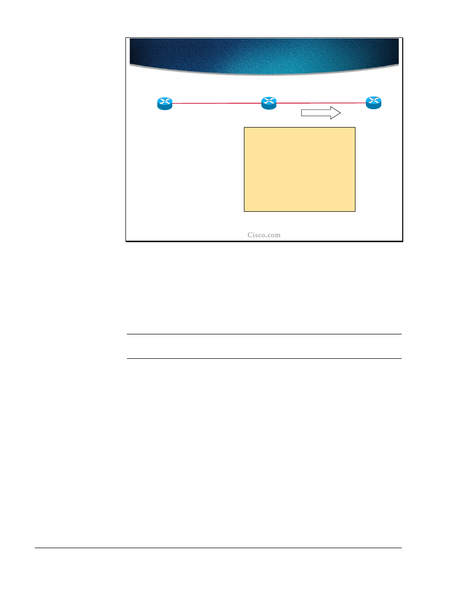
86
MPLS Traffic Engineering Technology
Copyright
2001, Cisco Systems, Inc.
© 2001, Cisco Systems, Inc.
MPLS Traffic Engineering Technology-94
Path Setup (Cont.)
Path Setup (Cont.)
Path:
Common_Header
Session(
R3-lo0, R1-lo0
)
PHOP(
R2-2
)
Label_Request(
IP
)
ERO (
R3-1
)
Session_Attribute (...)
Sender_Template(
R1-lo0,
00
)
Record_Route (
R1-2, R2-2
)
R2
R3
R1
2
2
1
1
As the next hop router (R2) receives the RSVP Path message, it places the
contents of ERO into its path state block and removes itself from the ERO (R2
removed the R2-1 entry from the ERO). Router R2 adjustthe PHOP to the
address of its own interface (the “2” interface at R2, R2-2) and adds the address
(R2-2) to the RRO. The Path message is then forwarded to the next-hop in the
ERO.
Note
Several other functions are performed at each hop as well, including the traffic
admission control.
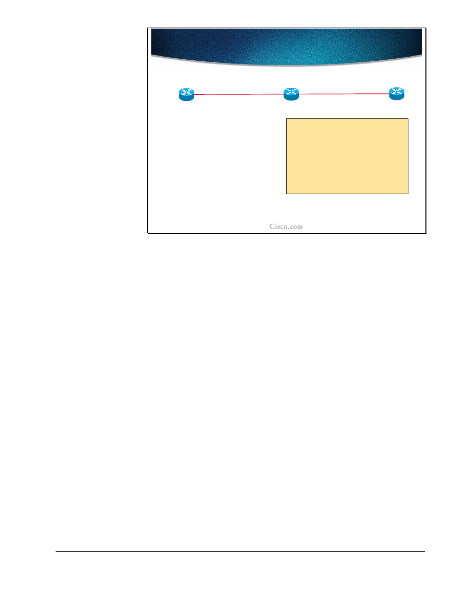
Copyright
2001, Cisco Systems, Inc.
MPLS Traffic Engineering Technology
87
© 2001, Cisco Systems, Inc.
MPLS Traffic Engineering Technology-95
Path Setup (Cont.)
Path Setup (Cont.)
Path State:
Session(
R3-lo0, 0, R1-lo0
)
PHOP(
R2-2
)
Label_Request(
IP
)
ERO ()
Session_Attribute (
...
)
Sender_Template(
R1-lo0,
00
)
Record_Route (
R1-2, R2-2, R3-1
)
R2
R3
R1
2
2
1
1
When the RSVP Path message arrives to the tail-end router (R3), the path state
block is created and the ERO becomes empty (after removing the router`s own
address from the list) indicating it has reached the tail-end of the tunnel. The RRO
at this moment contains the entire path from the head-end router.
The RSPV Resv message must be generated.
The Label Request object in the RSVP Path message requires the tail-end router
to allocate a label for the specified LSP tunnel (session).
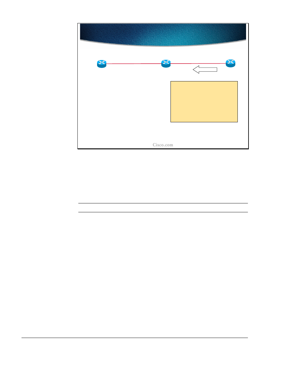
88
MPLS Traffic Engineering Technology
Copyright
2001, Cisco Systems, Inc.
© 2001, Cisco Systems, Inc.
MPLS Traffic Engineering Technology-96
Path Setup (Cont.)
Path Setup (Cont.)
Resv:
Common_Header
Session(
R3-lo0, 0, R1-lo0
)
PHOP(
R3-1
)
Sender_Template(
R1-lo0,
00
)
Label=
POP
Record_Route(
R3-1
)
R2
R3
R1
2
2
1
1
Since R3 is the tail-end router, it does not allocate a specific label for the LSP
tunnel. The implicit-null label is used instead (the value “POP” in the Label
object).
The PHOP in the RSVP Resv message is populated by the tail-end router’s
interface address and this address is copied to the RRO as well.
Note
The RRO is re-initiated in the RSVP Resv message.
The Resv message is forwarded to the next-hop address in the path state block of
the tail-end router. The next hop information in the path state block was
established when the Path message was traveling in the opposite direction (head-
end to tail-end).
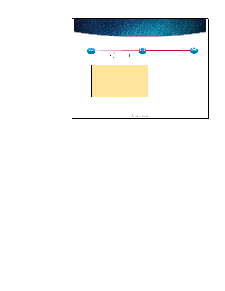
Copyright
2001, Cisco Systems, Inc.
MPLS Traffic Engineering Technology
89
© 2001, Cisco Systems, Inc.
MPLS Traffic Engineering Technology-97
Path Setup (Cont.)
Path Setup (Cont.)
Resv:
Common_Header
Session(
R3-lo0, 0, R1-lo0
)
PHOP(
R2-1
)
Sender_Template(
R1-lo0,
00
)
Label=
5
Record_Route(
R2-1
,
R3-1
)
R2
R3
R1
2
2
1
1
The RSVP Resv message travels back to the head-end router. On each hop (in
addition to the admission control itself) label handling is performed. From the
RSVP Resv message shown in the figure it is seen that the following actions were
performed at the intermediate hop (R2):
The R2’s interface address was put into the PHOP field and added to the
beginning of the RRO list.
The incoming label (5) was allocated for the specified LSP path.
Note
The label switch table is not shown but contains the information for label switching
(in this particular case the label “5” is replaced with an implicit-null label (“POP”).
The Resv message is forwarded towards the next hop listed in the path state block
of the router. The next hop information in the path state block was established
when the Path message was traveling in the opposite direction (head-end to tail-
end).
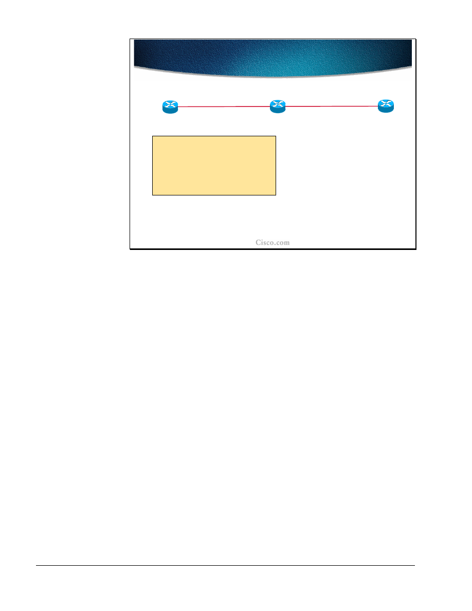
90
MPLS Traffic Engineering Technology
Copyright
2001, Cisco Systems, Inc.
© 2001, Cisco Systems, Inc.
MPLS Traffic Engineering Technology-98
Path Setup (Cont.)
Path Setup (Cont.)
Resv state:
Session(
R3-lo0, 0, R1-lo0
)
PHOP(
R2-1
)
Sender_Template(
R1-lo0,
00
)
Label=
5
Record_Route(
R1-2
,
R2-1
,
R3-1
)
R2
R3
R1
2
2
1
1
When the RSVP Resv message arrives at the head-end router (R1) the LSP path
setup is concluded. The label (5) allocated by the next-hop router towards the
tunnel endpoint (PHOP = R2-1) is stored and the explicit route taken by the tunnel
is present in RRO. The LSP tunnel is established.

Copyright
2001, Cisco Systems, Inc.
MPLS Traffic Engineering Technology
91
© 2001, Cisco Systems, Inc.
MPLS Traffic Engineering Technology-99
Trunk and Link Admission
Control
Trunk and Link Admission
Control
•
Invoked by RSVP Path message
–
Determines if resources are available
–
If bandwidth is not available, Link-level Call
Admission Control (LCAC says) no to RSVP and a
PathErr message is sent
•
If needed, a flooding of the node’s resource info
is triggered
–
If bandwidth is available, this bandwidth is put
aside in a waiting pool (waiting for the Resv msg)
•
Triggers IGP information distribution when
resource thresholds are crossed
One of the essential steps performed at each hop of the route to the LSP tunnel
endpoint (the trunk) is admission control, which is invoked by the RSVP Path
message traveling from the head-end to the tail-end router.
Each hop on the way determines if the available resources specified in the Session
Attribute object are available. Two situations can appear:
■
There is not enough bandwidth on a specified link through which the traffic
trunk (tunnel) should be established. The Link-level Call Admission Control
(LCAC) module informs RSVP about the lack of resources and RSVP
respectively generates the RSVP Patherr message with the code "Requested
bandwidth unavailable." Additionally, the flooding of the node`s resource
information (by the respective link-state IGP) can be triggered as well.
■
If the requested bandwidth is available, the bandwidth is reserved and is put
into a waiting pool waiting for the Resv message to confirm the reservation.
Additionally, if the resource threshold is exceeded, the respective IGP triggers
the flooding of the resource info.

92
MPLS Traffic Engineering Technology
Copyright
2001, Cisco Systems, Inc.
© 2001, Cisco Systems, Inc.
MPLS Traffic Engineering Technology-100
Link Admission Control
Link Admission Control
•
The process of LSP path setup may require
the pre-emption of resources
•
Link-level Call Admission Control (LCAC)
notifies RSVP of the pre-emption
•
RSVP sends PathErr and/or ResvErr for the
preempted tunnel
During the admission control, the priorities are checked as well. If the requested
bandwidth is available, but is in use by lower priority sessions, then lower priority
sessions (beginning with the lowest priority) may be pre-empted to free the
necessary bandwidth. There are 8 levels of priority, 0 being the highest, 7 being
the lowest.
When pre-emption is supported, each pre-empted reservation triggers a ResvErr
and/or PathErr message with the code "Policy Control failure".
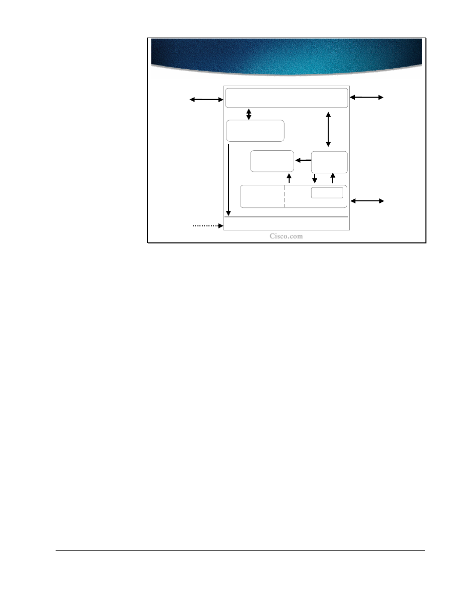
Copyright
2001, Cisco Systems, Inc.
MPLS Traffic Engineering Technology
93
© 2001, Cisco Systems, Inc.
MPLS Traffic Engineering Technology-105
Path Setup at Tunnel Midpoint
Path Setup at Tunnel Midpoint
Topology
Database
RSVP
Flooding
Routing
IS-IS/OSPF
Link
Admission
Control
MPLS Forwarding Table
Topology
RSVP
Label Manager
The figure shows a conceptual model of the actions taken at the tunnel midpoint.
The RSVP module is receiving signaling messages (Path) from upstream routers,
passing them onto the destination, receiving the reverse path messages (Resv)
from the destination, and passing them back towards the head-end of the tunnel.
The first action the RSVP performs (in addition to a regular RSVP setup) is to
invoke the MPLS-TE link admission control module. The module determines if
resources are available to admit the session (tunnel) or if existing sessions need to
be pre-empted. The information is signaled to the RSVP module.
Depending on the resource allocation associated with the session, the RSVP
module may invoke the IGP flooding module to cause the flooding of the new
reservation. .
If the session was admitted by link admission control, RSVP needs to take the
label received from the downstream router and establish proper entry in the MPLS
forwarding table via the RSVP label manager. The label is consequently
communicated to the upstream neighbor.

94
MPLS Traffic Engineering Technology
Copyright
2001, Cisco Systems, Inc.
© 2001, Cisco Systems, Inc.
MPLS Traffic Engineering Technology-102
Path Monitoring
Path Monitoring
•
MPLS-TE characterizes the traffic, and applies
control actions to drive the network to a desired
state
–
Establishment of LSP tunnels with or without QoS
requirements
–
Identification and diagnosis of LSP tunnels
–
Preemption of an established LSP tunnel under
administrative policy control
–
Dynamic rerouting of an established LSP tunnel
upon failure
–
Re-optimization of an LSP tunnel without
disruption of service
After the LSP path establishment, the path is constantly monitored to maintain the
network traffic trunk in a desired state. The Quality of Service (QoS) attributes
(like min. bandwidth and etc ……...) may be taken into account during the LSP
path setup and monitored in order to provide for the re-optimization of the tunnel
as well.
Various diagnostics are performed on the identified LSP paths and if necessary,
the tunnels are pre-empted following the administrative policy control or
dynamically rerouted in a case of network topology changes. The tunnels are also
monitored for re-optimization in a case of changes in available resources.
Note
.
It is highly desirable not to disrupt traffic while the tunnel rerouting is in progress.
This smooth rerouting requirement requires establishing a new LSP tunnel and
transferring traffic from the old LSP tunnel onto the new one before tearing down
the old LSP tunnel. The concept is called "make-before-break".

Copyright
2001, Cisco Systems, Inc.
MPLS Traffic Engineering Technology
95
© 2001, Cisco Systems, Inc.
MPLS Traffic Engineering Technology-103
Design Requirements Examples
Design Requirements Examples
•
Differentiating traffic trunks:
–
Critical traffic trunks must be well routed in preference to
other trunks
–
Ability to include/exclude certain links for certain trunks
•
Non-disruptive handling of changes in the network topology
–
Maintain the existing route until the new route is established
•
Non-disruptive optimization on new/restored bandwidth
–
Maintain the existing route until the new route is established
•
Handling failures
–
Automated re-routing in the presence of failures
To constantly provide optimal paths for the tunnels and to continuously meet the
traffic requirements when designing traffic trunks, several design requirements
and guidelines must be followed:
■
Traffic trunks must be differentiated. This differentiation includes both the
traffic trunk attributes as well as the physical link attributes.. Some critical
traffic trunks must have higher priority in preference to other trunks (that
might have to be pre-empted). Some physical links must be included/excluded
for certain trunks.
■
The changes in the network topology must be non-disruptive. Before the new
tunnel is fully established the existing path must be taken. It is better to lose
some traffic than forwarding traffic to a “black hole.”
■
The same policy as with topology changes applies to traffic trunks with
changes in link attributes. If changes in available bandwidth require re-
optimizing the tunnels, the former path must be used until the newly
established tunnel is established.
■
Traffic trunks must be automatically re-routed in a case of network failure.

96
MPLS Traffic Engineering Technology
Copyright
2001, Cisco Systems, Inc.
© 2001, Cisco Systems, Inc.
MPLS Traffic Engineering Technology-104
Path Rerouting—Re-optimization
Path Rerouting—Re-optimization
• Problem:
Some resources become available
resulting in non-optimal path of traffic trunks
• Solution:
Re-optimization
–
A periodic timer checks for the most optimal path
–
If a better LSP seems to be available:
•
The device attempts to signal the better LSP
•
If successful, replaces the old and inferior LSP
with the new and better LSP
The LSP path must be re-routed when there are physical (topology) failures
orwhen certain changes in resource usage require it. As resources in another part
of the network become available, the traffic trunks may have to be re-optimized.
The re-optimization is done on a periodic basis. At certain intervals, the checks
for the most optimal paths for LSP tunnels are done and if the current path is not
the most optimal, trunk re-routing is initiated.
The device (head-end router) first attempts to signal a better LSP and only after
the new LSP path setup has been established successfully, will the traffic be re-
routed from the former trunk to the new one.
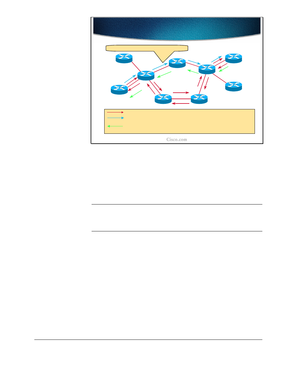
Copyright
2001, Cisco Systems, Inc.
MPLS Traffic Engineering Technology
97
© 2001, Cisco Systems, Inc.
MPLS Traffic Engineering Technology-105
Non-disruptive Rerouting -
Re-optimization
Non-disruptive Rerouting -
Re-optimization
POP
22
49
17
R8
R2
R6
R3
R4
R7
R1
R5
R9
32
Some bandwidth became available again.
Current Path (ERO = R1->R2->R6->R7->R4->R9)
New Path (ERO = R1->R2->R3->R4->R9) - shared with current path
and reserved for both paths.
Until R9 gets new Path message, current Resv is refreshed -
PathTear can then be sent to remove old path (and release
resources)
resources)
.
.
38
89
26
The example in the figure shows how the non-disruptive re-routing of the traffic
trunk is performed. Initially the Explicit Route Object (ERO) lists the LSP path
R1-R2-R6-R7-R4-R9, with R1 as the head-end and R9 as a tail-end of the trunk.
The changes in available bandwidth on the link R2-R3 dictate that the LSP Path
be re-optimized. The new path R1-R2-R3-R4-R9 is being signaled and parts of the
path overlap with the existing path. Still the current LSP path is used.
Note
On links that are common to the old and new LSPs, resources used by the old
LSP tunnel should not be released before traffic is moved to the new LSP tunnel,
and reservations should not be counted twice (this might cause the Admission
Control to reject the new LSP tunnel).
After the new LSP path is successfully established, the traffic is rerouted to the
new path and the reserved resources of the previous path are released.. The
release is done by the tail-end initiating a RSVP PathTear message.
The labels that are allocated during the RSVP Path setup are shown as well. The
tail-end router assigns the implicit-null (POP) label.

98
MPLS Traffic Engineering Technology
Copyright
2001, Cisco Systems, Inc.
© 2001, Cisco Systems, Inc.
MPLS Traffic Engineering Technology-106
Link Failure
Link Failure
•
Repair at the head-end of the tunnel in the
event of failure of an existing LSP
–
IGP or RSVP alarms the head-end
•
New path for LSP is computed and eventually
a new LSP is signaled
•
Tunnel interface goes down if there is no LSP
available for 10s
When a link passed by a certain traffic trunk fails, the head-end of the tunnel
detects that failure by either:
■
The IGP (OSPF or IS-IS) sends a new link-state packet with information
about changes that have happened.
■
RSVP alarms the failure by sending an RSVP PathTear message to the head-
end.
Link failure detection without any pre-configured or pre-computed path at the
head-end results in a new path calculation (using a modified SPF algorithm) and
consequently in a new LSP path setup.
Note
The tunnel interface used for the specified traffic trunk (LSP path) goes down if
the specified LSP path is not available for 10 seconds. In the meantime the traffic
intended for the tunnel continues using a broken LSP path resulting in black-hole
routing.

Copyright
2001, Cisco Systems, Inc.
MPLS Traffic Engineering Technology
99
© 2001, Cisco Systems, Inc.
MPLS Traffic Engineering Technology-107
Link Failure and Alternative Path
Link Failure and Alternative Path
•
Example: One link along a dynamic tunnel LSP path goes down
–
RSVP Tear causes the head-end to flag LSP as dead
–
RSVP session is cleared
–
PCALC triggered:
•
No alternative path
–
Head-end sets the tunnel down
•
Alternative path found
–
New LSP directly signaled
–
Adjacency table updated for the tunnel interface
–
Cef table updated for all entries resolving on this
tunnel adjacency
When the router along the dynamic LSP path detects a link failure it sends the
RSVP PathTear message to the head-end. This messages signals to the head-end
that the tunnel is down. The head-end clears the RSVP session and a new Path
calculation (PCALC) is triggered using a modified SPF algorithm. There are two
possible outcomes of the calculation:
■
No new path is found. The head-end sets the tunnel interface down.
■
Alternative path is found. The new LSP path setup is triggered by RSVP
signalization and adjacency tables for the tunnel interface are updated. Also
the CEF table is updated for all the entries that resolve to this tunnel
adjacency.

100
MPLS Traffic Engineering Technology
Copyright
2001, Cisco Systems, Inc.
© 2001, Cisco Systems, Inc.
MPLS Traffic Engineering Technology-108
Two Tunnels to the Same
Destination
Two Tunnels to the Same
Destination
•
The search for an alternative path and its signaling
can take time and impact the packet forwarding
•
Solution with two tunnels:
–
One tunnel could be configured as backup to
another tunnel
–
Both tunnels would have the same destination
–
LSP for the secondary tunnel is pre-signaled and
available if the first tunnel fails
•
Must use diverse path from the primary
–
Traffic is switched back on the primary tunnel if it
succeeds in establishing a session
Since the time elapsed between the link failure detection and the new LSP path
establishment can cause delays for critical traffic, there is a possibility of using
alternative pre-established paths (backup). Therefore, there are two tunnels
between the same endpoints at the same time.
Note
The requirement is that pre-configured tunnels between the same endpoints must
use diverse paths.
As soon as the primary tunnel fails the traffic is transitioned to the backup tunnel.
The traffic is returned back to the primary tunnel if the conditions provide for the
re-establishment.
Note
Having two pre-established paths is the simplest form of MPLS-TE path
protection. Another option is to use the pre-computed path only and establish the
LSP path on-demand. In the latter case, there is no overhead in resource
reservations.
Several preparation steps must be taken in order for effective switching of the
traffic between the tunnels.

Copyright
2001, Cisco Systems, Inc.
MPLS Traffic Engineering Technology
101
© 2001, Cisco Systems, Inc.
MPLS Traffic Engineering Technology-111
IP Routing over Tunnels
IP Routing over Tunnels
• Static routing:
Two floating statics to the primary
and backup tunnel
• Autoroute:
The IP MPLS-TE tunnel metric is the IGP
cost to the tunnel end-point, regardless of the
actually taken path
–
Change the IP MPLS-TE tunnel metric to prefer
one tunnel over the other
•
Absolute - a positive metric value can be
supplied
•
Relative - a positive, negative or zero value to
the IGP metric can be supplied
•
Example:
primary: relative –1; secondary: null
In the presence of two tunnels, the primary (which is active) and the secondary,
two routing options exist:
■
Static routing with two floating static routes pointing to the tunnels.
■
Autoroute feature” In this case the traffic trunk (tunnel) metric is the IGP cost
to the tunnel end-point, regardless of the actual path taken. By adjusting this
metric, the primary tunnel can be made preferential. The metric adjustments
can be:
–
absolute (a positive metric value is assigned to the tunnels) or
–
relative (the IGP metric is changed for a relative value, which can be
either negative, 0 or positive). In the example, primary: relative –1;
secondary: null, the secondary tunnel metric is not changed at all (0)
and the primary tunnel metric is decreased by 1 (assuming that the
lower metric is a better metric).
Note
The autoroute feature is explained in detail in the Assigning Traffic to Traffic
Trunks lesson, which follows this lesson.
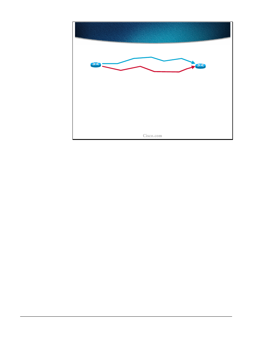
102
MPLS Traffic Engineering Technology
Copyright
2001, Cisco Systems, Inc.
© 2001, Cisco Systems, Inc.
MPLS Traffic Engineering Technology-110
Tunnel1
Tunnel2
(backup)
LSP1
LSP2
Path Protection with
Preconfigured Tunnels
Path Protection with
Preconfigured Tunnels
•
Preconfigured tunnels speed-up recovery by moving
the traffic on a pre-installed LSP as soon as the
head-end learns the primary LSP is down
•
Drawbacks:
–
Backup tunnel allocates labels and reserves
bandwidth
–
Double counting of reservations via RSVP
The example in the figure shows two pre-configured tunnels: Tunnel1 (LSP1) is a
primary tunnel and Tunnel2 (LSP2) is a backup tunnel. Their physical paths are
diverse.
The switch-over to the backup tunnel is done at the head-end as soon as the
primary tunnel failure is detected (via RSVP or via IGP). There is an obvious
benefit to having a pre-configured backup tunnel. However, the solution presents
some drawbacks as well:
■
The backup tunnel requires all the mechanisms as the primary one. The labels
must be allocated and bandwidth reserved for the backup tunnel as well.
■
Looking only from the RSVP perspective, the resource reservations
(bandwidth) are counted twice.

Copyright
2001, Cisco Systems, Inc.
MPLS Traffic Engineering Technology
103
© 2001, Cisco Systems, Inc.
MPLS Traffic Engineering Technology-111
Smooth Re-optimization
Smooth Re-optimization
•
Objective:
Set-up a tunnel that is capable of
maintaining resource reservations (without
double counting), while it is being rerouted
or while it is attempting to increase its
bandwidth
–
Allows receiver to explicitly specify
senders to be included in reservation
–
Single reservation on a link for all the
senders listed
The drawbacks of configuring two tunnels and reserving resources twice can be
overcome by single reservations on the same link (crossed by the same tunnel)
that are not counted twice. These path re-optimization mechanisms are used
during the path rerouting or while attempting to increase the tunnel bandwidth.
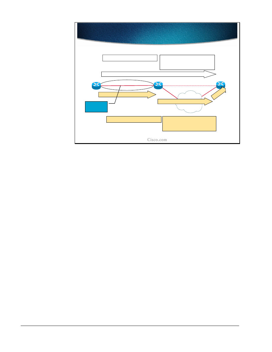
104
MPLS Traffic Engineering Technology
Copyright
2001, Cisco Systems, Inc.
© 2001, Cisco Systems, Inc.
MPLS Traffic Engineering Technology-112
Make Before Break
Make Before Break
R2
R3
R1
ERO (
R2-1, R3-1
)
Sender_Template(R1-lo0
,
00
)
Style=SE
2
3
1
3
1
2
Session #1(R3-lo0, R1-lo0)
ERO (
R2-1, …, R3-3
)
Sender_Template(R1-lo0,
01
)
Style=SE
00
01
01
01
Resource
Sharing
Session #2 (R3-lo0, R1-lo0)
In the initial Path message, the head-end (ingress node) forms a Session object,
and a Sender_Template (aLSP_ID is 00) with a “Shared Explicit” flag set. The
tunnel set-up then proceeds according to the normal procedure.
On receipt of the Path message, the tail-end (egress node) sends a Resv message
in which it indicates “Shared Explicit” path toward the ingress node. When an
ingress node with an established path wants to change that path, it forms a new
Path message. The existing Session object with a new LSP_ID (01) in the
Sender_Template object is used. The ingress node creates an ERO for the new
route. The new Path message is sent.
Since the receiver of the RSVP Path message realizes (based on the LSP_ID) that
the second reservation belongs to the same session, it reserves resources only
once.

Copyright
2001, Cisco Systems, Inc.
MPLS Traffic Engineering Technology
105
© 2001, Cisco Systems, Inc.
MPLS Traffic Engineering Technology-113
Path and Link Protection
Path and Link Protection
•
Fast Reroute Link Protection allows for
temporarily routing around a failed link while
the head-end is reoptimizing the LSP
–
Controlled by the routers sharing the failed
link
–
In the event of a link failure, an LSP is
rerouted to the next-hop using a
preconfigured backup tunnel
–
Session_Attribute’s Flag 0x01 allows the
use of Link Protection for the signaled LSP
To speed-up the path re-optimization or rerouting while the head-end is
performing new path calculation, the Fast ReRoute option of MPLS-TE is
available. The function is performed by routers directly connected to the failed
link and is called Link Protection. The failed link causes the LSP to be rerouted to
a pre-configured tunnel and therefore bypass the failed link.
The Fast ReRoute option is supported by setting one of the Session attributes that
allows link protection.

106
MPLS Traffic Engineering Technology
Copyright
2001, Cisco Systems, Inc.
© 2001, Cisco Systems, Inc.
MPLS Traffic Engineering Technology-118
Link Protection for R2-R4 link
Link Protection for R2-R4 link
Pop
22
17
R8
R2
R6
R4
R7
R1
R5
R9
Bypass (backup) static tunnel (R2->R6->R7->R4) temporary route to
take in the event of a failure.
End-to-end tunnel onto which data normally flows (R1->R2->R4->R9).
37
14
Pop
The example shows the link protection on the link between R2 and R4. The traffic
trunk between R1 and R9 passes this link when the link is up and provides
required resources.
The pre-configured tunnel between R2 and R4 takes the path R2-R6-R7-R4 and
uses all the mechanisms of MPLS-TE (labels are allocated, resources reserved).
This tunnel (link protection LSP) serves as a temporary backup in case the R2-R4
link fails. The Fast ReRoute option is certainly a benefit to LSP path rerouting
because only a part of the resources are reserved in advance (only the tunnel that
backs-up the protected link).

Copyright
2001, Cisco Systems, Inc.
MPLS Traffic Engineering Technology
107
© 2001, Cisco Systems, Inc.
MPLS Traffic Engineering Technology-115
Link Down Event
Link Down Event
•
Head-end is notified by RSVP PathErr and by
IGP
•
Special flag in RSVP PathErr (reservation in
place) indicates that the path states must not
be destroyed
•
Original LSP nested within link protection
LSP
•
Rerouting under 50ms (time to detect and
reroute)
When the protected link fails, the RSVP PathErr message and the normal IGP
link-state mechanisms is used to notify the head-end . A special flag in the RSVP
PathErr message indicates that the failed link already has a backup LSP, which
must be taken into consideration when re-optimizing the failed path. In terms of
reservations, it can be said that the original LSP is nested within the link
protection LSP.
The rerouting with such a pre-configured tunnel is almost instant. The rerouting
takes less than 50 milliseconds and the delay is caused only by the time it takes to
detect the failed link and to switch the traffic to the link protection LSP. The latter
includes some label handling as well.
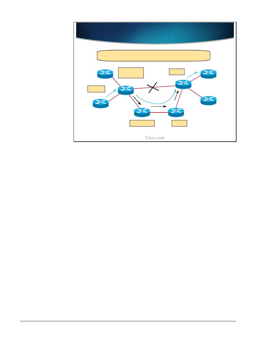
108
MPLS Traffic Engineering Technology
Copyright
2001, Cisco Systems, Inc.
© 2001, Cisco Systems, Inc.
MPLS Traffic Engineering Technology-120
Link Protection Active
Link Protection Active
R8
R2
R6
R4
R7
R1
R5
R9
Push 37
22 Pop
Swap 37->14
Push 17
Swap 17->22
14 Pop
On failure of link from R2-> R4, R2 simply changes outgoing
Label Stack from 14 to <17, 14> (nested LSPs).
Pop
22
17
37
14
Pop
During the Fast reroute phase, the LSP labels must be handled as well. The router
at the head-end of the link protection LSP changes the original outgoing label for
the label of the pre-established LSP and nests the original label within the label
stack.
In the example the original labels assigned to the LSP (listed from R1 to R9) are:
37-14-POP (implicit null). The labels on the link protection LSP are (listed from
R2 to R4): 17-22-POP (implicit null). The only change in the link failure event
happens on R2 where it swaps the incoming label 37 to 14. However since the
link with assigned label 14 is not available, the path is moved to the link
protection LSP. The original label 14 is put on the label stack of the link
protection LSP to which an outgoing label 17 was assigned. Thus the original LSP
path is effectively nested within the link protection path.

Copyright
2001, Cisco Systems, Inc.
MPLS Traffic Engineering Technology
109
© 2001, Cisco Systems, Inc.
MPLS Traffic Engineering Technology-117
R8
R2
R6
R4
R7
R1
R5
R9
Resv
Resv
state
Resv
state
Resv State while Rerouting
Resv State while Rerouting
Resv message is unicast to the Phop (R2) - R6 and R7 have not seen the Path
message. R2’s Path state has been informed that the Resv might arrive over a
different interface as the one used by the Path message.
The loss of the interface does not affect the Path and Resv states for
the LSP’s received on that interface that are marked fast reroutable!
The RSVP states should not be affected by the Fast reroute function. In fact, the
Path and Resv messages still logically flow across the failed link. The PHOP for
the Resv message traveling via R4 towards the head-end (R1) is unchanged and is
still the R2 address. The R2 is aware that the response (Resv message) to the Path
message might arrive via a different interface due to the link failure.
Since R6 and R7 have not seen the Path message (it passed the R2-R4 link) they
could have problems in handling the Resv message flowing back (and thus
maintaining RSVP states). To overcome the problem the Resv message is sent by
the R4 directly to a unicast address of the R2.

110
MPLS Traffic Engineering Technology
Copyright
2001, Cisco Systems, Inc.
© 2001, Cisco Systems, Inc.
MPLS Traffic Engineering Technology-118
Path Adjustment With
Autobandwidth
Path Adjustment With
Autobandwidth
•
Traffic engineering automatic bandwidth feature
adjusts the bandwidth allocation for TE tunnels
based on their measured traffic load
–
Periodically changes tunnel bandwidth (BW)
reservation based on traffic out tunnel
–
The average output rate is sampled for each
tunnel
–
The allocated bandwidth is periodically adjusted
to be the largest sample for the tunnel since the
last adjustment
Traffic engineering automatic bandwidth adjustment provides the means to
automatically adjust the bandwidth allocation for traffic engineering tunnels
based on their measured traffic load.
Traffic engineering autobandwidth samples the average output rate for each
tunnel marked for automatic bandwidth adjustment. For each marked tunnel, it
periodically (for example, once per day) adjusts the tunnel's allocated bandwidth
to be the largest sample for the tunnel since the last adjustment.
The frequency with which tunnel bandwidth is adjusted and the allowable range
of adjustments is configurable on a per-tunnel basis. In addition, the sampling
interval and the interval over which to average the tunnel traffic to obtain the
average output rate, is user-configurable on a per-tunnel basis.
The benefit of the autobandwidth feature is that it makes it easy to configure and
monitor the bandwidth for MPLS traffic engineering tunnels. If automatic
bandwidth is configured for a tunnel, traffic engineering automatically adjusts the
tunnel's bandwidth.
The automatic bandwidth adjustment feature treats each tunnel for which it has
been enabled independently. That is, it adjusts the bandwidth for each such tunnel
according to the adjustment frequency configured for the tunnel and the sampled
output rate for the tunnel since the last adjustment, without regard for any
adjustments previously made or pending for other tunnels.
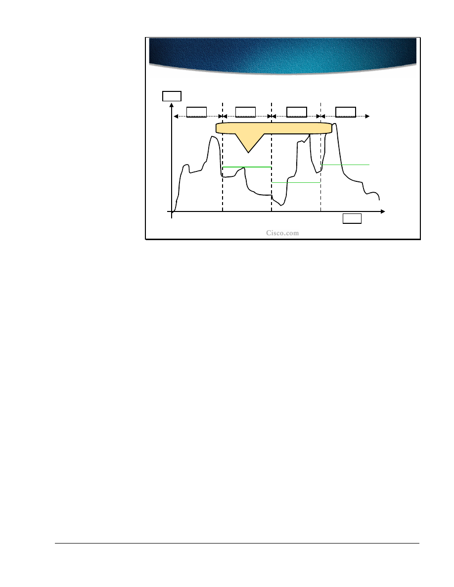
Copyright
2001, Cisco Systems, Inc.
MPLS Traffic Engineering Technology
111
© 2001, Cisco Systems, Inc.
MPLS Traffic Engineering Technology-119
Autobandwidth Example
Autobandwidth Example
5 min
5 min
5 min
5 min
Curently allocated bandwidth
Time
Load
The diagram shows the load on the tunnel and intervals of measurement. The
input and output rates on the tunnel interfaces are averaged over a predefined
interval (load-interval). In the example, the interval is the last 5 minutes.
The automatic bandwidth adjustments are done periodically, for example, once
per day. For each tunnel for which automatic bandwidth adjustment is enabled,
the platform maintains information about sampled output rates and the time
remaining until the next bandwidth adjustment.
When the adjustments are done, the currently allocated bandwidth (shown as
horizontal solid lines in the diagram) is reset to the maximum of:
■
The largest average rate sampled during the time from the last bandwidth
adjustment.
■
The configured maximum value.
If the new bandwidth is not available, the previously allocated bandwidth is
maintained.

112
MPLS Traffic Engineering Technology
Copyright
2001, Cisco Systems, Inc.
Summary
After completing this lesson, you should be able to perform the following tasks:
■
Describe the MPLS-TE path setup procedures
■
Explain the details of RSVP assistance in MPLS TE path setup
■
Describe the functions of trunk and link admission control
■
Explain path monitoring and rerouting
■
List the methods for path and link protection
■
Explain the traffic trunk re-optimization and bandwidth requirement
adjustments
Lesson Review
1. How is an LSP path setup initiated?
2. List the main components (objects) of RSVP messages that help establish the
MPLS-TE tunnel.
3. How does Link-level Call Admission Control (LCAC) signal the inability to
reserve the required bandwidth?
4. How is the LSP path non-disruptively rerouted?
5. List the LSP path protection methods.
6. What is a major benefit of the Fast Reroute function?
7. What is the purpose of the autobandwidth feature of MPLS-TE?

Copyright
2001, Cisco Systems, Inc.
MPLS Traffic Engineering Technology
113
Assigning Traffic to Traffic Trunks
Objectives
Upon completion of this lesson, you will be able to perform the following tasks:
■
List the mechanisms that can be used to assign traffic to traffic trunks
■
Describe the auto-route mechanism
■
Use static routes to assign traffic to traffic trunks
■
Use static routes or auto-route toward next-hop routers in combination with
exterior routing protocols

114
MPLS Traffic Engineering Technology
Copyright
2001, Cisco Systems, Inc.
© 2001, Cisco Systems, Inc.
MPLS Traffic Engineering Technology-125
Traffic Flow Modifications with
Static Routes and Policy Routing
Traffic Flow Modifications with
Static Routes and Policy Routing
• CBR
used to find the path for an LSP tunnel
• IP
is on top of LSP routing and does not see
internal details
•
Tunnels can only be used for routing if they
are explicitely specified
–
Static route in the IP routing table points to
a selected LSP tunnel interface
–
Policy routing - the next-hop interface is a
LSP tunnel
The Label Switched Path (LSP) is computed by the Constraint-Based Routing
(CBR), which takes the resource requirements into consideration as well. When
the LSP path is established for the trunk, the traffic can flow across it. From the
IP perspective, an LSP path is a simple tunnel.
These engineered tunnels can only be used for the IP routing if the tunnels are
explicitly specified for routing:
■
Via static routes that point to the tunnel
■
Via policy routing that sets a next-hop interface to the tunnel
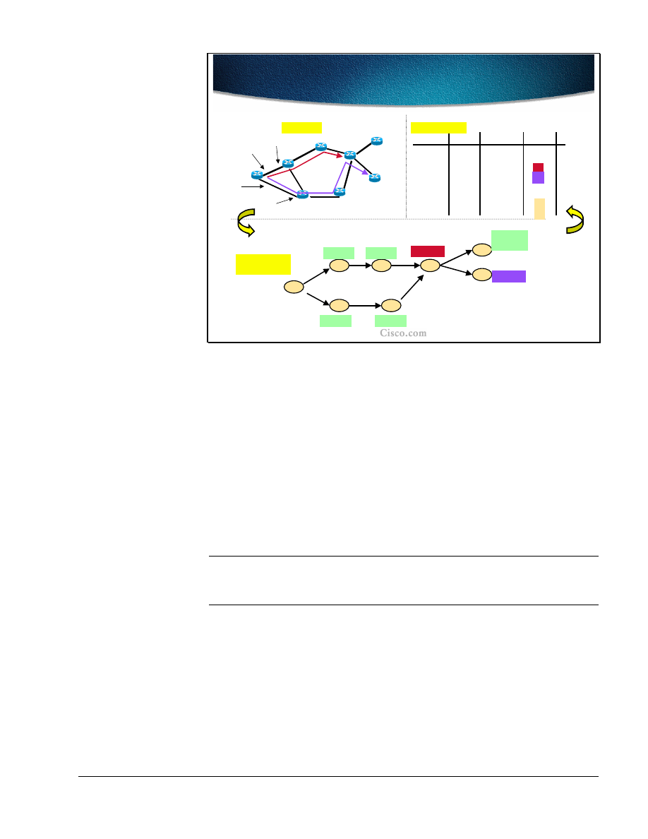
Copyright
2001, Cisco Systems, Inc.
MPLS Traffic Engineering Technology
115
© 2001, Cisco Systems, Inc.
MPLS Traffic Engineering Technology-130
Static routing on R1 Pointing to Tunnel
Interfaces (T1 and T2) for R4 and R5
Static routing on R1 Pointing to Tunnel
Interfaces (T1 and T2) for R4 and R5
R1
R2
R3
R4
R6
R7
R8
R5
(T1, R4)
(I1, A1)
(I1, A1)
(T2, R5)
(I2, A2)
(I2, A2)
Shortest-Path
Tree
Shortest-Path
Tree
Address A2
R8
R2
R6
R3
R4
R7
R1
R5
Interface I1
Address A1
Interface I2
Ri’s loopback is i.i.i.i
Topology
T1
T1
T2
T2
Dest
Out Intf
Next Hop
2.2.2.2
I1
A1
3.3.3.3
I1
A1
4.4.4.4
T1
R4
5.5.5.5
T2
R5
6.6.6.6
I2
A2
7.7.7.7
I2
A2
Routing Table
Metric
1
2
3
4
1
2
8.8.8.8
I1
A1
I2
A2
4
4
{(I1, A1),
(I2, A2)}
The example topology shows two engineered tunnels: T1 (between R1 and R4)
and T2 (between R1 and R5). The loopback addresses on each router are in the
form i.i.i.i where i is the router number (e.g. R5’s loopback address is 5.5.5.5).
The metric on each of the interfaces is set to 1.
R1 has two physical interfaces: I1 and I2, and two neighboring routers (next hops)
with addresses A1 and A2 respectively.
The routing table lists all eight loopback routes and associated information. Only
the statically configured destinations (R4 and R5) list tunnels as their outgoing
interfaces. For all other destinations the normal IGP routing is used and results in
physical interfaces (along with next hops) as the outgoing interfaces towards these
destinations. The metric to the destination is normal IGP metric.
Note
Even for the destination that is behind each of the tunnel endpoints (R8), the
normal IGP routing is performed if there is no static route to the traffic engineered
tunnel.
The SPF calculates paths to destinations in its usual way with the exception of the
paths for the tunnels where a constraint-based computation is performed.

116
MPLS Traffic Engineering Technology
Copyright
2001, Cisco Systems, Inc.
© 2001, Cisco Systems, Inc.
MPLS Traffic Engineering Technology-127
MPLS-TE Solving the BGP Next-
hop Problem
MPLS-TE Solving the BGP Next-
hop Problem
• Solution 1:
Tunnel T1 with relative IP MPLS-TE
metric –6 and static route for next-hop on T1
• Solution 2:
Tunnel T1 with absolute IP MPLS-TE
metric 29 and static route for next-hop on T1
•
All traffic from R1 to the Ethernet will go via R2
R1
R2
R3
R4
IGP shortest path: R1_to_R2: 35
IGP shortest path: R1_to_R3: 30
Problem: Assume that BGP next-hop is not set to self on R2 and R3, the
BGP local preference cannot be used to prefer R2 over R3 for exit.
T1
T2
There are several interesting problems associated with MPLS-TE routing. In the
example in the figure, there are two internal routers serving exits to external BGP
destinations – R4 (including the Ethernet between R2, R3 and R4). These two
routers are also the endpoints of two MPLS-TE tunnels. The BGP next-hop self is
not configured on R2 and R3 (the R4 remains the next hop), which prevents the
use of local preference to prefer R2 to R3 as an exit to external destinations. The
best IGP metric is used instead, and R3 becomes the preferred exit.
There are two possible solutions to the problem. Both solutions use the static
routes to MPLS-TE tunnels and some metric modifications (relative or absolute
metrics):
■
The metric for tunnel T1 is set to a relative value decreased by 6 (35-6=29)
and the static route for the Ethernet is configured to the tunnel T1
■
The metric for tunnel T1 is set to an absolute value of 29 and the static route
for the Ethernet is configured to the tunnel T1
In both cases all the traffic for the Ethernet will flow via R2 since its metric less
than 30

Copyright
2001, Cisco Systems, Inc.
MPLS Traffic Engineering Technology
117
© 2001, Cisco Systems, Inc.
MPLS Traffic Engineering Technology-128
IP Forwarding Database
Modification with Autoroute
IP Forwarding Database
Modification with Autoroute
•
Autoroute feature enables the head-end to
see the LSP as a directly connected interface
–
Only for the SPF route determination, not
for the Constraint-based path computation
–
All traffic directed to prefixes topologically
behind the tunnel endpoint (tail-end) is
forwarded onto the tunnel
•
Autoroute affects the head-end only; other
routers on the LSP path do not see the tunnel
To overcome the problems resulting from static routing configuration onto the
MPLS-TE tunnels, the autoroute feature of Cisco IOS was introduced. The
autoroute feature enables the head-end routers to see the MPLS-TE tunnel as a
directly connected interface and use it in its modified SPF computations.
The MPLS-TE tunnel is only used for normal IGP route calculation (at the head-
end only) and is not included in any constraint-based path computation.
The autoroute feature results in all the prefixes topologically behind the MPLS-
TE tunnel endpoint (tail-end) to be reachable via the tunnel itself (unlike with
static routing where only statically configured destinations were reachable via the
tunnel).
The autoroute feature affects the head-end router only and has no effect on
intermediate routers. These routers still use normal IGP routing for all the
destinations.

118
MPLS Traffic Engineering Technology
Copyright
2001, Cisco Systems, Inc.
© 2001, Cisco Systems, Inc.
MPLS Traffic Engineering Technology-129
Autoroute Path Selection Rules
Autoroute Path Selection Rules
•
The cost of the TE tunnel is equal to the shortest IGP
metric to the tunnel endpoint; the metric is tunable
•
If the tunnel metric is:
–
equal or lower than the native IGP metric, the
tunnel replaces existing next-hops; otherwise the
tunnel is not considered for routing
–
equal to other TE tunnels, the tunnel is added to
the existing next-hops (paralel paths)
•
Tunnels can be load-balanced (CEF mechanism) -
tunnel bandwidth factor considered
Since the autoroute feature includes the MPLS-TE tunnel into the modified SPF
path calculation, the metric of the tunnel plays a significant role. The cost of the
tunnel is equal to the best IGP metric to the tunnel endpoint regardless of the LSP
path. The tunnel metric is tunable using either relative or absolute metrics.
When installing the best paths to the destination, the tunnel metric is compared to
other existing tunnel metrics and to all the native IGP path metrics. The lower
metric is better and if the MPLS-TE tunnel has an equal or lower metric than the
native IGP metric, it is installed as a next hop to the respective destinations.
If there are tunnels with equal metrics they are installed in the routing table and
provide for load balancing. The load balancing is done proportionally to the
configured bandwidth of the tunnel.
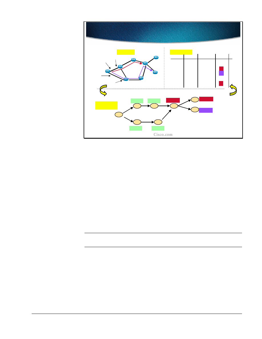
Copyright
2001, Cisco Systems, Inc.
MPLS Traffic Engineering Technology
119
© 2001, Cisco Systems, Inc.
MPLS Traffic Engineering Technology-130
Example: Autoroute is Turned on
Tunnels T1 and T2
Example: Autoroute is Turned on
Tunnels T1 and T2
R1
R2
R3
R4
R6
R7
R8
R5
(T1, R4)
(I1, A1)
(I1, A1)
(T1, R4)
(T2, R5)
(I2, A2)
(I2, A2)
Shortest-Path
Tree
Shortest-Path
Tree
Address A2
R8
R2
R6
R3
R4
R7
R1
R5
Interface I1
Address A1
Interface I2
Ri’s loopback is i.i.i.i
Topology
T1
T1
T2
T2
Dest
Out Intf
Next Hop
2.2.2.2
I1
A1
3.3.3.3
I1
A1
4.4.4.4
T1
R4
5.5.5.5
T2
R5
6.6.6.6
I2
A2
7.7.7.7
I2
A2
8.8.8.8
T1
R4
Routing Table
Metric
1
2
3
4
1
2
4
The example topology shows two engineered tunnels: T1 (between R1 and R4)
and T2 (between R1 and R5). The loopback addresses on each router are in the
form i.i.i.i where i is the router number (e.g. R5’s loopback address is 5.5.5.5).
The metric on each of the interfaces is set to 1.
R1 has two physical interfaces,I1 and I2, and two neighboring routers (next hops)
with addresses A1 and A2 respectively.
The routing table lists all eight loopback routes and associated information. The
autoroute feature is turned on for both tunnels (T1 and T2) at their head-end
(router R1).
The routing table shows all destinations at the endpoint of the tunnel and behind it
(R8) as reachable via the tunnel itself. The metric to the destination is normal IGP
metric.
Note
Unlike the static route configuration with autoroute feature the destinations behind
the tunnel endpoints (R8 in this example) are reachable via the tunnel as well.
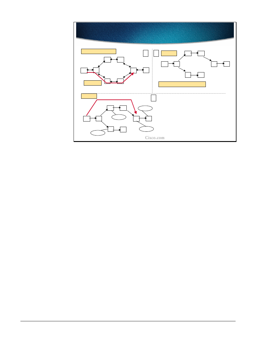
120
MPLS Traffic Engineering Technology
Copyright
2001, Cisco Systems, Inc.
© 2001, Cisco Systems, Inc.
MPLS Traffic Engineering Technology-131
Example 1: Autoroute
Example 1: Autoroute
A
B
C
D
E
F
G
H
100
Default link metric: 10
A
B
C
D
E
F
G
H
A
B
C
D
E
F
G
H
IP TE metric=40 (not 130)
0
1
2
B’s View
A’s View
TE Tunnel
B does not see the TE Tunnel.
2/8
1/8
3/8
4/8
NH
Metric
1/8
B
30
2/8
TE Tunnel
50
3/8
B
30
4/8
TE Tunnel
60
The following examples show the effect of the autoroute feature. In the first
situation there is an MPLS-TE tunnel configured between A and G. The tunnel is
seen for routing purposes only by the head-end (A). Intermediate routers do not
see the tunnel nor do they take it into consideration for route calculations.
Although the LSP paths follow the path A-B-E-F-G, the tunnel cost is the best
IGP metric to the tunnel endpoint. The link metric between F and G is 100. All
other metrics are set to 10. Although the LSP path passes the F-G link, the overall
metric of the tunnel is 40 (the sum of metrics on the best IGP path A-B-C-D-G).
In the routing table all the networks topologically behind the tunnel endpoint
(networks 2 and 4) are reachable via the tunnel itself since the MPLS-TE tunnel
metric is equal to the native IGP metric, it is installed as a next hop to the
respective destinationsThis is the effect of the autoroute feature. The metrics to
these two networks are the sums of the tunnel metric (40) and the native IGP
metric from the tunnel endpoint to the respective networks.
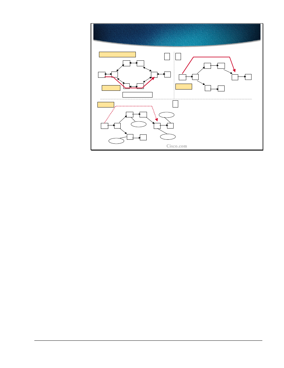
Copyright
2001, Cisco Systems, Inc.
MPLS Traffic Engineering Technology
121
© 2001, Cisco Systems, Inc.
MPLS Traffic Engineering Technology-132
Example 2: Relative Metric
Example 2: Relative Metric
A
B
C
D
E
F
G
H
100
Default link metric: 10
A
B
C
D
E
F
G
H
0
1
2
A’s View
TE Tunnel
2/8
1/8
3/8
4/8
NH
Metric
1/8
B
30
2/8
B
50
3/8
B
30
4/8
B
60
Relative metric: +2
A
B
C
D
E
F
G
H
IP TE metric=42
A’s View
The tunnel metrics can be tuned and either relative or absolute metrics can be
used. In the second example, the LSP path still takes the same path (A-B-E-F-G),
but the tunnel metric is set to relative+2. This setting results in a tunnel metric of
42.
When the tunnel is considered in the IGP calculation the native IGP metric (40) is
lower than the tunnel metric (42) for all the destinations topologically behind the
tunnel endpoint. As a result, all the destination networks (1 to 4) are reachable via
router B instead of via the TE tunnel as can be seen from the routing table.
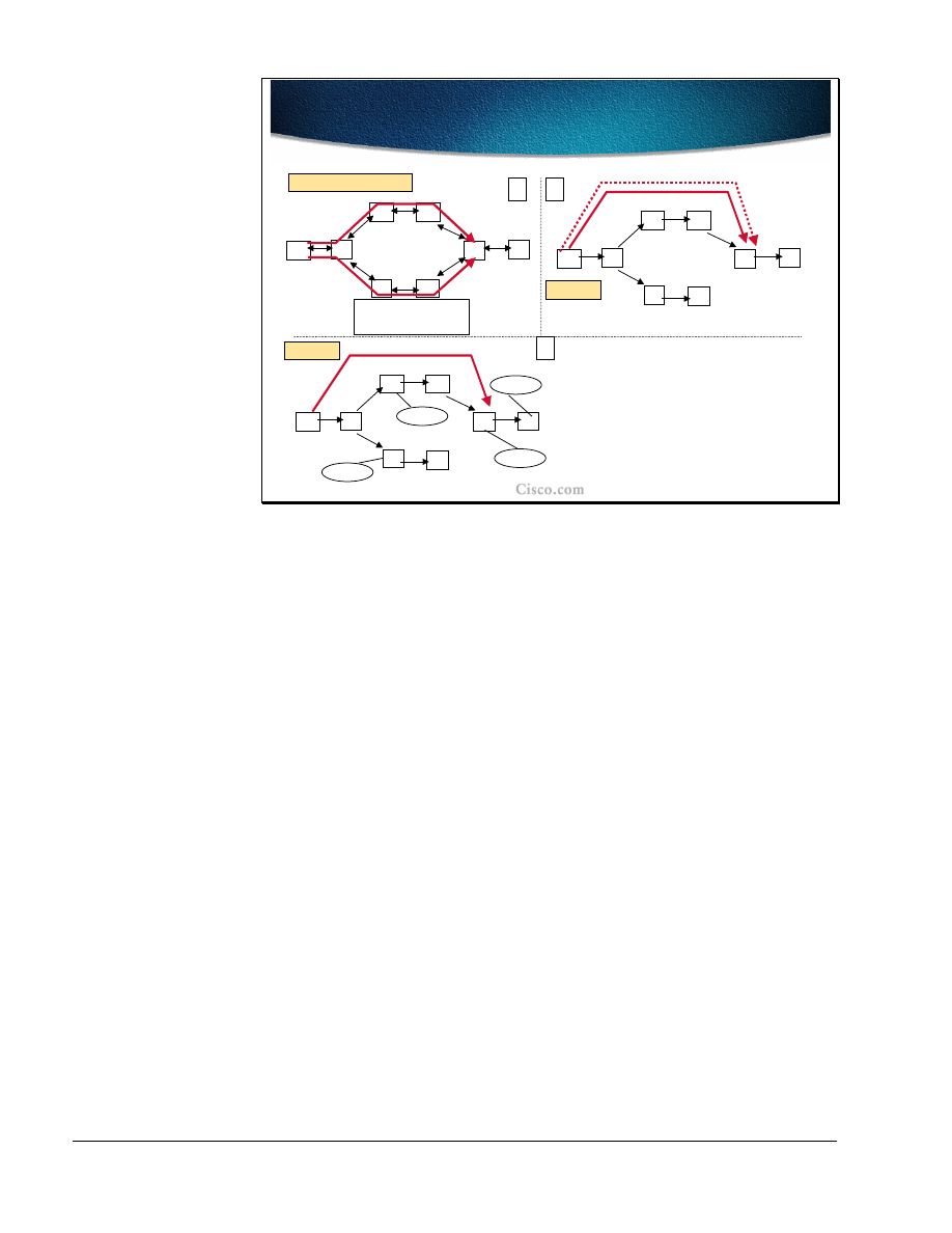
122
MPLS Traffic Engineering Technology
Copyright
2001, Cisco Systems, Inc.
© 2001, Cisco Systems, Inc.
MPLS Traffic Engineering Technology-133
Example 3: Two Tunnels
Example 3: Two Tunnels
A
B
C
D
E
F
G
H
100
Default link metric: 10
A
B
C
D
E
F
G
H
0
1
2
A’s View
2/8
1/8
3/8
4/8
NH
Metric
1/8
B
30
2/8
TE Tunnel 1
48
3/8
B
30
4/8
TE Tunnel 1
58
A
B
C
D
E
F
G
H
A’s View
T1: Relative metric: -2
T2: Relative metric: 0
IP T2 metric=40
IP T1 metric=38
IP T1 metric=38
T1
T2
In the third example of the autoroute feature there are two configured MPLS-TE
tunnels: T1 (following the LSP path A-B-C-D-G) and T2 (following the path A-B-
E-F-G). The metric of T1 is tuned to relative-2. This setting results in a T1 metric
of 38. The T2 metric is unchanged and is set to the best IGP metric to the tunnel
endpoint (40).
Both tunnel metrics are equal to or less than the native IGP metric to the tunnel
endpoints (40). Therefore both the tunnels are used: T1 as a primary tunnel and
T2 as a secondary tunnel. All the destinations behind the T1 endpoint are
reachable via the tunnel itself due to the autoroute feature. As seen from the
routing table, the networks 2 and 4 are reachable via T1 and their respective
metrics are sums of the tunnel metric and the native IGP metric from the tunnel
endpoint to the respective networks.
The secondary tunnel (t2) is used as a backup and provides for a fast transition
from the primary tunnel in a case of failure. The drawback is that T2 reserved the
bandwidth, which cannot be used by other tunnels.
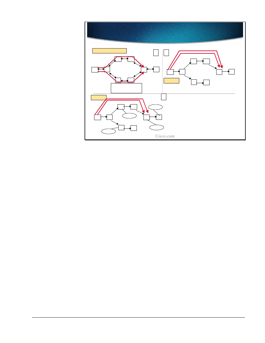
Copyright
2001, Cisco Systems, Inc.
MPLS Traffic Engineering Technology
123
© 2001, Cisco Systems, Inc.
MPLS Traffic Engineering Technology-134
Example 4: Load Balancing
Example 4: Load Balancing
A
B
C
D
E
F
G
H
100
Default link metric: 10
A
B
C
D
E
F
G
H
0
1
2
A’s View
2/8
1/8
3/8
4/8
A
B
C
D
E
F
G
H
A’s View
T1: Relative metric: 0
T2: Relative metric: 0
IP T2 metric=40
IP T1 metric=40
T1
T2
Prefix
NH
Metric
1/8
B
30
2/8
TE Tunnel 1
TE Tunnel 2
50
3/8
B
30
4/8
60
TE Tunnel 1
TE Tunnel 2
The last example of the autoroute feature shows two configured tunnels: T1
(following the LSP path A-B-C-D-G) and T2 (following the path A-B-E-F-G).
The relative tunnel metrics are unchanged and equal to the native IGP metric to
the tunnel endpoints. In both cases, the tunnel metric is 40.
Since both tunnel metrics are equal to the native IGP metrics, the tunnels are
preferred routing paths for all the destinations behind the tunnel endpoints
(networks 2 and 4) and thus both tunnels appear in the routing table.
The load balancing across the parallel paths is done in proportion to the
configured bandwidth on the tunnel.

124
MPLS Traffic Engineering Technology
Copyright
2001, Cisco Systems, Inc.
Summary
After completing this lesson, you should be able to perform the following tasks:
■
List the mechanisms that can be used to assign traffic to traffic trunks
■
Describe the auto-route mechanism
■
Use static routes to assign traffic to traffic trunks
■
Use static routes or autoroute toward next-hop routers in combination with
exterior routing protocols
Lesson Review
1. Explain the drawbacks of the static assignment of traffic to MPLS-TE
tunnels.
2. What are the benefits of using the autoroute feature in MPLS-TE?
3. Which path is preferred when using the autoroute feature for the destinations
behind the tunnel endpoints?
4. How is load-balancing done on two equal-cost MPLS-TE tunnels?

Copyright
2001, Cisco Systems, Inc.
MPLS Traffic Engineering Technology
125
Summary
After completing this module, you should be able to perform the following tasks:
■
Explain the need for traffic engineering to optimize network resources
■
Describe the concepts of MPLS traffic engineering
■
Identify MPLS traffic engineering features
■
Explain the tunnel path attributes and setup procedures
■
Describe the tunnel path maintenance
■
Explain the enhanced traffic engineering features such as autobandwidth or
guaranteed bandwidth

126
MPLS Traffic Engineering Technology
Copyright
2001, Cisco Systems, Inc.
Appendix: Answers to Review Questions
Traffic Engineering Concepts
1. How can an overlay network provide traffic engineering?
Layer-2 PVCs or SVCs can be created to use the appropriate links.
2. What are the drawbacks of using overlay networks?
Two networks must be managed.
The layer-3 network must be highly meshed.
Overlay networks always require an extra layer of encapsulation.
The layer-2 devices do not have any layer-3 knowledge for intelligent
queuing and dropping.
3. Why does traditional IP packet forwarding not distribute the load over all
links?
The IGP will make one decision as to how to reach any destination.
Then all traffic towards that destination follows that route.
4. Can IP source-routing be used to overcome the problems of overlay
networks??
No. Source-routing is most likely not available.
5. Can policy-base routing be used to overcome the problems of overlay
networks?
No. It is not scalable.
6. What does MPLS provide that allows for Traffic Engineering?
Packet forwarding based on labels and not based on IP destination
addresses.
7. Which IGPs can be used to calculate an LSP for an MPLS-TE tunnel?
IS-IS and OSPF (both require the traffic engineering extensions)
8. How is the MPLS-TE LSP created?
Manually, by configuration, or automatically using the RSVP protocol.
MPLS Traffic Engineering Components
1. What are the characteristics of a traffic trunk?
A routable object characterized with ingress and egress LSR routers
(head-end and tail-end), its forward equivalence class and a set of
attributes.
2. What modifications are needed to the IGP to support MPLS-TE?
The IGP has to be able to communicate the resource attributes to the
network (in addition to the link states).

Copyright
2001, Cisco Systems, Inc.
MPLS Traffic Engineering Technology
127
3. What is a result of a Constraint-based path calculation?
The LSP is specified with the list of IP addresses (next-hops) between
the tunnel endpoints.
4. Explain the role of RSVP in MPLS-TE.
RSVP is used in LSP path signaling to ensure the label allocation and
bandwidth reservation.
5. How is traffic mapped to the MPLS-TE tunnel?
Traffic is mapped statically using static routes, with policy routing, or
dynamically using the autoroute feature.
Constraint-based Path Computation
1. List the major MPLS-TE link attributes that influence the LSP path
computation.
Maximum Allocation Multiplier (bandwidth), Link Resource Class,
Constraint-based Specific Link Metric.
2. List the major traffic trunk attributes that influence the LSP path computation.
Traffic Parameter (required bandwidth), Trunk Resource Class Affinity,
Setup and Hold priority.
3. How are link attributes known to the head-end of the traffic trunk?
Using the modified link-state IGP that floods link resources.
4. How can a certain link be excluded from the LSP path computation?
Using the proper setting of link resource class bit settings and trunk
resource class affinity bits along with resource class mask.
5. Which path is selected when there are several equal-cost LSP path
candidates?
The path with the highest minimum bandwidth, then the paths with
lower hop count, then random selection.
Path Setup and Maintenance
1. How is an LSP path setup initiated?
By the head-end using the RSVP signalization.
2. List the main components (objects) of RSVP messages that help establish the
MPLS-TE tunnel.
Label_Request, Explicit_Route, Record_Route and Session_Attribute
objects.
3. How does Link-level Call Admission Control (LCAC) signal the inability to
reserve the required bandwidth?
LCAC notifies the RSVP, which in turn sends a PathErr message and if
needed, the resources information are flooded by the IGP.
4. How is the LSP path non-disruptively rerouted?

128
MPLS Traffic Engineering Technology
Copyright
2001, Cisco Systems, Inc.
By establishing the new LSP first and then tearing down the old one
(make-before-break concept).
5. List the LSP path protection methods.
By having two pre-configured tunnels (primary and secondary).
6. What is a major benefit of the Fast Reroute function?
The Fast ReRoute function allows for temporary rerouting around a
failed link while the head-end is re-optimizing the path.
7. What is the purpose of the autobandwidth feature of MPLS-TE?
To optimize the bandwidth usage by periodic adjustments of the
allocated bandwidth with respect to the actual bandwidth usage by the
tunnels.
Assigning Traffic to Traffic Trunks
1. Explain the drawbacks of the static assignment of traffic to MPLS-TE
tunnels.
The tunnel is used only for explicit routes that are statically defined.
2. What are the benefits of using the autoroute feature in MPLS-TE?
The autoroute feature enables the tunnel to also be used for the
destinations that topologically lie behind the tunnel endpoints.
3. Which path is preferred when using the autoroute feature for the destinations
behind the tunnel endpoints?
The tunnel if its metric is equal or lower than the native IGP metric.
4. How is load-balancing done on two equal-cost MPLS-TE tunnels?
Proportionally to the tunnel bandwidth.
Wyszukiwarka
Podobne podstrony:
Traffic Engineering in MPLS based VPNs
DISTILLING KNOWLEDGE new histories of science, technology, and medicine
DISTILLING KNOWLEDGE new histories of science, technology, and medicine
02 2007 Engine Technology
Volksgemeinschaft Engineers; The Nazi Voyages of Technology
PORÓWNYWANIE TECHNOLOGII
19 Mikroinżynieria przestrzenna procesy technologiczne,
Technologia informacji i komunikacji w nowoczesnej szkole
Technologia spawania stali wysokostopowych 97 2003
SII 17 Technologie mobilne
W WO 2013 technologia
TECHNOLOGIA PŁYNNYCH POSTACI LEKU Zawiesiny
technologia prefabrykowana
Technology & Iventions
Technologia Maszyn CAD CAM
World of knowledge
więcej podobnych podstron