83109 Kenwood378$

Connecting Cables to Terminals
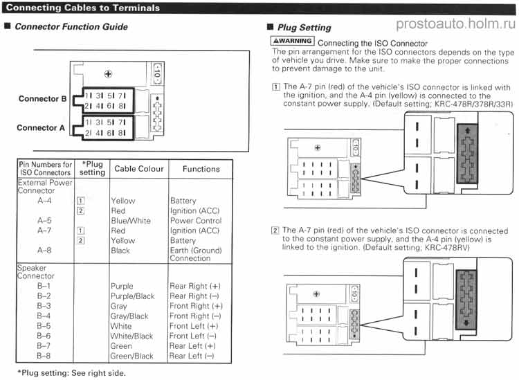
■ Connector Function Guide
|
$ |
lir o O | ||
|
Connector B |
r-Jil 31 51 71 41 61 81 |
Ś | |
|
Connector A |
Jli 31 51 71 Li. 41 61 81 |
r j |
|
Pm Numbers for ISO Connectors |
*Plug setting |
Cable Colour |
Functions |
|
External Power Connector | |||
|
A-4 |
CC |
Yeltow |
Battery |
|
[Ł |
Red |
Ignitron (ACC) | |
|
A-5 |
Blue/White |
Power Controf | |
|
A-7 |
U |
Red |
Igmiion (ACO |
|
I) |
Yełlow |
Battery | |
|
A-8 |
Black |
Earth fGround) Connoction | |
|
Speaker Connector | |||
|
B-l |
Purple |
Rear Right (+) | |
|
B-2 |
Purpfe/Black |
Rear Right (-) | |
|
B-3 |
Cray |
Front Right (+) | |
|
B-4 |
Gray/Black |
Front Right H | |
|
B-5 |
White |
Front Left (+> | |
|
B-6 |
White/Black |
Front Left (—ł | |
|
B-7 |
Green |
Rear Left 1+) | |
|
B-B |
Green/Black |
Rear Left H |
piug setting: See nght side.
■ Plag Setting prostoauto. holm. ru
AWARNINO] Connectmg the ISO Connector
The pm arrangement for the ISO connectors depends on the type of vehicle you drive Make surę to make the proper connections to prevent damage to the unit
ffi
The A-7 pm (redl oł the vehicle’s ISO connector is linked with the ignition, and the A-4 pin (yellowl is connected to the constant power supply. (Default setting. KRC-478R/378R/33RI
|
r= ■ 1 |
• • 1 Irin |
|
r |
• • d Is |
|
J. |
i 111 |
|
i |
• i • |
[2' The A-7 pin (redl of the vehicle‘s ISO connector is connected to the constant power supply. and the A-4 pm (yellowl is linked to the ignition (Default setting; KRC-478RV)
|
1 |
_j | |||
|
q + 11 |
1 | |||
|
J 1 1 i i '| 0 |
1 | |||
|
4 I | ||||
|
i i i i |
1 |
■j | ||
|
U-. 1 1 ' 1 -tf | ||||
Wyszukiwarka
Podobne podstrony:
Kenwood378# Connecting Cables to TerminalsISO connector unsupported car (KRC-478R/378R/33R only) ACA
functionblock Usc thc pulldown menu :it the top of thc scrccn to sclcct a diffcrenł function bł
Obraz (4) 186 Asymilacja to termin Piageta opisujący przyswajanie informacji przy użyciu
S7301363 d warunkuje rozwój tylko u osób ... e. inne 8. Wartość, oczekiwanie, relewantność, aktywacj
11184 skanuj0003 Zaburzenia seksualne to termin mało precyzyjny, najogólniej oznacza on jakąś patolo
Cyberprzestrzeń, cyberprzestępczość i cyberterroryzm to terminy ściśle ze sobą powiązane. Natomiast
„Trójkąt śmierci" to termin kliniczny odnoszący się do regionu anatomicznego twarzy, zawartego
„Trójkąt śmierci" to termin kliniczny odnoszący się do regionu anatomicznego twarzy, zawartego
The Writing Skills Teaching of this skill should proceed through controlled, guided to free writing
wstęp 2 ...masaż czy masaży ki... Masaż dziecięcy to termin, który funkcjonuje w literaturze naukowe
JOGGING Fogging to termin który określa zjawisko kondensacji pary wodnej na powierzchni folii w post
więcej podobnych podstron