crt superstar900ït manual (16) wm

ALTERNATE MICROPHONES AND INSTALLATION
Ihc conncctions. Kccp the cxposcd wire lcngths to a minimum to avoid shorting u hen Ihc microphonc pług is rcasscmbled.
Lin Number
l or best results. the user should sclcct a low-impcdancc dynamie typc microphone or a transistorized microphonc. Transistorizcd type microphoncs have Iow output impcdancc charactcristies. I hc microphoncs must bc provided with a four-lead cablc. The audio conductor and its shicldcd Iead comprisc two of the leads. The third lead is for transmit control and fourth is for recciving eon troi.
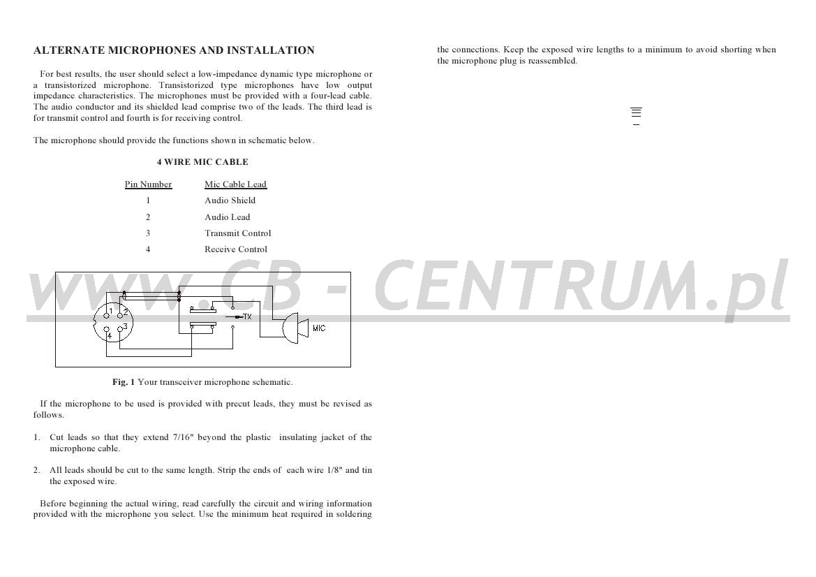
The microphonc should providc the funetions shown in schematie bclow.
4 WIRE MIC CABLE
Mie Labie l.ead
1 Audio Shield
2 Audio Lead
3 Transmit Control
4 Recehe Control

Fig. 1 Your transcciver microphone schematie.
If the microphonc to be used is providcd with prccut leads. they must bc re\ ised as follows.
1. Cut leads so that they extend 7/16" bcyond the plastic insulating jackct of the microphonc cable.
2. Ali leads should be cut to the same length. Strip the ends of eaeh wire 1/8" and tin the cxposcd wire.
Bcfore beginning the actual wiring, read carefully the circuit and wiring information proyided with the microphonc you sclcct. Use the minimum heat rcquircd in soldering
Wyszukiwarka
Podobne podstrony:
crt superstar900?t manual (17) wm Fig. 3 Microphonc pług pin numbcrs vieved 1 rom rear of pin rc cc
crt superstar900?t manual (10) wm GENERAL Model SS-3900EFT Froquency RangÄ™ 28.245 ~ 29.655 MHz l
crt superstar900?t manual (11) wm IGNITION NOISE INTERFERENCE Use of a mobile receiver at Iow signal
crt superstar900?t manual (12) wm 11 you’re having difficulties in adjusling your antcnna. chcck thc
crt superstar900?t manual (13) wm 5. E-TONE CONTROL : This control is uscd to cont
crt superstar900?t manual (14) wm REAR PANEL 1. ANTEN NA : I his jack accepts 50 o
crt superstar900?t manual (15) wm DRECEIY INC SSB SIGNALS Therc arc four lypcs of signals prcscntly
crt superstar900?t manual (19) wm Bon cle Gccrcintie ci conserver Sans le Cachet du Distribuleur, la
crt superstar900 manual (10) wm ELEMENTS MODIFIANTSLA PORTEE DE YO I RE CB. Ce sonc priacipalement l
crt superstar900 manual (11) wm CONDITIONS DE GARANTIE Les ćmetteurs-rćcepteurs CRT SUPERSTAR sont g
crt superstar900 manual (12) wm SA AU CAPITAL DE 3 500 000 FF PROPRIETAIRE ET IMPORTATEUR OFFICEEL D
crt superstar900 manual (13) wm GAMMĘ DE FREQUENCE DISPONIBLECANA.UX
crt superstar900 manual (15) wm DEUX OPTIONS POSSIBLESA. Rćference : SfflPSSSSIfAR KF VI AD002200 (F
crt superstar900?t manual wm SUPERSTAR SARL au Capital de 762 500 € Route de Pagny 21250 SEURRE - Fr
crt superstar900?t manual (1) wm TABLE DES MATIERES CARACTERISTIOUES
crt superstar900?t manual (2) wm LANGAGE INTERNATIONAL DES RADIOAMATEURS QRA Domicile de 1 operate
crt superstar900?t manual (3) wm 11. INDICATEUR TX/RX : LED bicolorc signalant 1 ć
crt superstar900?t manual (4) wm CB - CE MONTAGE DUN POSTE CB DANS UNE VOITURE PORTE FUSIBLE POSTE C
crt superstar900?t manual (5) wm 4- L ANTENNE A/ Å‚. utilisation d une antenne 28 Mhz est indispensab
więcej podobnych podstron