372596191
RIKEN Accel. Próg. Rep. 24 (1990)
V-2-32. Bellows Assembly with RF Sliding Finger Shielding
T. Nishidono, T. Bizen,1 H. Daibo, Y. Suzuki,1 and S.H. Be
In the design of a bellows assembly, a special effort must be madę to minimize its RF imped-ance, because, in a storage ring, the maximum beam current depends greatly on the impedance. Therefore the bellows assembly is to be designed with no change in the cross-section as much as possible by shielding with RF fingers. Further-more the bellows assembly should have some tolerance for the variation in the longitudinal direction of the vacuum chamber caused by ther-mal expansions and contractions due to baking and temperaturę fluctuations of the cooling water and ambient air. In addition, the assembly should compensate manufacturing tolerance and alignment errors in the longitudinal and trans-verse direction. Alignment errors are considered to be ±2.5 mm in the longitudinal directiton and up to ±1 mm in the transverse direction.
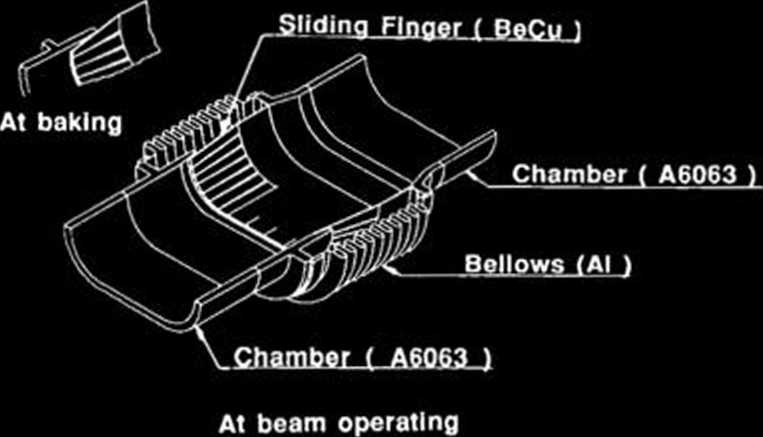
The length of slide fingers and their contact forces must be chosen so as to ensure a good electrical connection between the fingers and the inner surface of the chamber. Since the vacuum chamber with a slot to be used in the SPring-8 storage ring has a different structure from the chambers in an existing storage ring, bellows assemblies which have been using so far are not suitable to our storage ring. Therefore we are now developing a bellows assembly as shown in Fig. 1.
To make a large contact force, we designed the sliding fingers which contact the inclined inner surface of chambers with half cylindrical contact projections. The sliding fingers will be madę of a beryllium copper alloy (JIS C1720P-1/ 4H) of high electrical conductivity, high strength, and nonmagnetism. Depending on a temperaturę in use, a residual stress of the alloy is relaxed with a time at high temperaturę: 80% after 5000 hours bakeout at 150 °C. A relationship between the stress relaxation and a Larson-Miller param-eter is given in Fig. 2, which shows that the stress relaxation must be considered at the initial stage of design.
|
^ 100 * 80 c -S 60 OJ X 40 | ||||||
|
-«Q | ||||||
|
\ « \ | ||||||
|
Be Cu |
" J4ht | |||||
|
—— HU <D CC 20 n |
o 100 a ISO x 200 |
■C •C *C | ||||
|
1- | ||||||
i2 14 16 18 20
p=(-f-T + 492) (20 +log t) X 10-
Fig. 2. Relationship between stress relaxation and a Larson-Miller parameter.
i

Fig. 1. Schematic diagram of a sliding finger for the bellows.
i
Fig. 3. Photograph of a model of a sliding finger.
Ishikawajima-Harima Heavy Industries Co., Ltd.
Wyszukiwarka
Podobne podstrony:
92 RIKEN Accel. Próg. Rep. 24 (1990)111-5. Instrumentation1. Design of a Microbeamline for a Compact
94 RIKEN Accel. Próg. Rep. 24 (1990)111-5-2. Design of a Decay Muon Channel Using an Axially Symmetr
102 RIKEN Accel Próg. Rep. 24 (1990)111-5-8. Performance of Isotopic Separation in RIPS T.Nakamura,
103 RIKEN Accel. Próg. Rep. 24 (1990)111-5-9. Test Experiment of the GARIS/IGISOL K. Morita, T. Nomu
105 RIKEN Accel. Próg. Rep. 24 (1990)111-5-10. Velocity Distribution of IGISOL lon Beams M. Koizumi,
108 RIKEN Accel. Próg. Rep. 24 (1990)111-5-12. Status Report of the RIKEN Swinger-Magnetic Analyzer
110 RIKEN Accel. Próg. Rep. 24 (1990)111-5-14. Test for Dispersive-Mode Beam Transportto the SMART
116 RIKEN Accel. Próg. Rep. 24 (1990)111-5-19. Responses of Large Position-Sensitive Detectorsto Hea
121 RIKEN Accel. Próg. Rep. 24 (1990)IM-5-23. A Test for SMART Neutron Detectors H. Orihara, K. Hata
RIKEN Accel. Próg. Rep. 24 (1990)111-5-25. High Speed Serial Data Link for PC-9801 J. Fujita > PC
129 RIKEN Accel. Próg. Rep. 24 (1990)IV-2. Cross Section Data for 68Ge ProductionY. Tendow, A. Hashi
132 RIKEN Accel. Próg. Rep. 24 (1990)IV-5. Cross Sections Calculated by an ALICE Codęin the A = 50 —
133 RIKEN Accel. Próg. Rep. 24 (1990)V. DEVELOPMENT OF ACCELERATOR FACILITIES1. lon Accelerator Deve
138 RIKEN Accel. Próg. Rep. 24 (1990)V-l-4. RIKEN (Japan)-RAL (U.K.) Collaboration on Muon Science R
5 RIKEN Accel. Próg. Rep. 24 (1990)11-2. RILAC Operation Y. Chiba, M. Hemmi, M. Yanokura, M. Kasę, E
158 RIKEN Accel. Próg. Rep. 24 (1990)V-2-ll. Bump Magnet of SPring-8 H. Miyade, H. Takebe, and S. Mo
160 RIKEN Accel. Próg. Rep. 24 (1990)V-2-12. Measurement of a 508 MHz Model Coupler forthe SPring-8
168 RIKEN Accel. Próg. Rep. 24 (1990)V-2-16. All-Metal Gate Valve with an RF Contact S. Yokouchi, K.
więcej podobnych podstron