5441336704
Electrical & Computer Engineering: An International Journal (ECIJ) Yolume 3, Number 2, June 2014
5. SYSTEM SIMULATION AND LOAD FLOW ANALYSIS

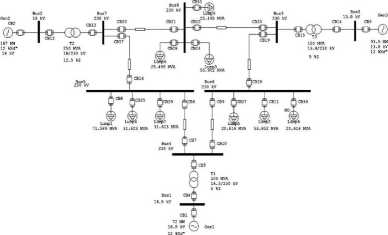
Fig. 2 Single Linę Diagram of IEEE 9 Bus test system
In this paper IEEE 9 bus system is used as the test system, which is simulated on ETAP 7.5.1.
The single linę diagram (SLD) of the simulated test system on ETAP is shown in Fig 2. For this test system generator and load parameters are given in appendix. The total generation is 313MW and total load is 312.5MW. The test system contains 6 lines connecting the bus bars in the system with the generator connected to network through step-up transformer at 230kV transmission voltage.
It is good practice to have periodic and updated load flow study for every installation. The purpose of load flow study is
i. To calculate bus voltage levels tocompare to equipment ratings anddistribution system operatingreąuirements
ii. To calculate branch current flows for comparing it to eąuipment ampacity ratings and protective device triplevels.
Depending upon the type of plant there can be many load flow cases to study. The objective is to identify the best and worst operating conditions. Several load flow solution algorithms used in industry such as Gauss-Seidel, Newton-Raphson and current injection. There is reąuirement of at least one swing bus in the network for all the Load flow solution algorithms. The utility point of service is always modeled as swing bus.
The result of load flow analysis when all generators and loads are operating at rated power is given in Table.l. Calculation of critical clearing time (CCT) by using EEAC for different generation and loading condition at the different fault locations are shown in Table. 2.
46
Wyszukiwarka
Podobne podstrony:
Electrical & Computer Engineering: An International Journal (ECIJ) Yolume 3, Number 2, June 2014
Electrical & Computer Engineering: An International Journal (ECIJ) Yolume 3, Number 2, June 2014
Electrical & Computer Engineering: An International Journal (ECIJ) Yolume 3, Number 2, June 2014
Electrical & Computer Engineering: An International Journal (ECIJ) Volume 3, Number 2, June 2014
Electrical & Computer Engineering: An International Journal (ECIJ) Volume 3, Number 2, June 2014
Electrical & Computer Engineering: An International Journal (ECIJ) Volume 3, Number 2, June 2014
Electrical & Computer Engineering: An International Journal (ECIJ) Volume 3, Number 2, June 2014
Electrical & Computer Engineering: An International Journal (ECIJ) Volume 3, Number 2, June 2014
Electrical & Computer Engineering: An International Journal (ECIJ) Volume 3, Number 2, June 2014
Electrical & Computer Engineering: Au International Journal (ECIJ) Yolume 3. Numbcr 2. June 2014
Electrical & Computer Engineering: An International Journal (ECIJ) Volume4. Number 3. September
Electrical & Computer Engineering: An International Journal (ECU) Yolume 4. Nuinber 2. June
Ekctrical & Computer Engineenng: An International Journal (ECU) Yolume3. Number Z June 2014 The
Ekctrical & Computer Engineering: An International Journal (ECU) VoIume3. Number Z June 2014 Tab
Ekctrical & Computer Engineering: An International Journal (ECU) Volume3. Number i June 2014 P l
Elcctrical & Computer Emaneering; An International Journal <ECU) Vohime 2. Number 1. Nlarch 2
Efcctrical & Computer Engincering: An International Journal (ECU) Volume4. N umbcr 3. Septcmber
Elcctrical & Computer Enginccring: An International Journal t ECU) Volumc 3. Numbcr 2. Junc 2014
Ekctrical & Computer Eng ince ring: An International Journal < ECU) Volume4. N untber 3. Sept
więcej podobnych podstron