6837092904
Diagnostyka’ 4(48)/2008
BARSZCZ, MAŃKA, Application ofHardware-In-Loop for 1'irlual Power Piani
• reply of malfunctioiis to analyze real cases from the plant:
• modeling of faulty behavior of a plant to improve the knowledge about processes in the real plant
• simulation of various modifications of the unit and effects it will have. for example in the dynamie State:
• huge resource for search of diagnostic rules. tlius it will bring advances in FDI techniques:
• development of risk management algorithms:
• verification of diagnostic Systems in operation on a plant.
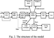
The Virtual Power Plant [4] is the group of computcrs. coimected by a fast Computer network (see Fig. 1). Each Computer plays a role of a VPP component. The largest part of the system is database. which consists of two cooperating subsystems. The First one is the database as in the typical DCS system. This allows to storę the data in the same way they are stored in a real system. The second database subsystem is a specialized. fast database which is used to storę data generated by modules of the VPP. Tliis subsystem is proprietaiy. efficient database engine. which can also storę dynamie data (e.g. vibration wavefonns). The Central Bus is another Computer, which is the main data exchange hub in the VPP. It provides conunon interface for all the modules. which allows to derelop each module independent from the others. Tlie remaining computers are used to run inodels of the components of the power plant. Fig. 2 presents the structure of the VPP model. The mathematical model used in the Virtual Power Plant is a compromise between the reąuirements of the accuracy to the real object and available computing and data processing power [5], On the other liand. its structure allows for easy excliange of several components. depending on reąuirements of the application.
As presented on the Fig. 2. modeling of the dynamie State is weakly coupled with the rest of the model. There are no feedbacks and tliere is only one signal determining the vibration. i.e. rotational speed. Since on the Ust of applications presented above, the iinportant one is verification of vibration monitoring and diagnostic Systems (VMDS) in operation on a plant, there was a necd to generate real-time yibration signals. which could be comerted to analogue signals and fed into a yibration monitoring system. With proposed approach. it would be possible to test VMDS in \arious conditions, also impossiblc to simulate on a real power generation unit. Since the model was developed as the variable step Matlab/Simulink model, it did not generate such signals and other real time simulation techniąues were necessaiy.

2. REAL TIME SIMULATIONS
Real-time system can be divided into two main categories:
• Hard real-time system - where Uming correctness is critical for the system and can't be sacrificed for otlier benefits.
• Soft real-time systeins - where time correctness is iinportant. but not critical and can be sacrificed for other goals (for exainple model accuracy).
Typical real-time system consists of two parts: controller and controlled system. Depending of structure of these two parts real-time siinulations can be diyided into :
• Rapid prototyping of control Systems;
• Hardware-In-The-Loop.
Nowadays there are two major systems used for real-time siinulations:
• Systems based on FPGA systems - used inostly for fast prototyping:
• Systems based on DSP cards - used eąually for fast prototyping and HIL siinulations.
The system presented in the paper is based on the second solution for real-time siinulations. dSPACE is one of the proi iders of real-time systems based on DSP s. They provide vide variety of systems designed for fast prototyping and HIL siinulations. Systems offered by dSPACE varies from simple single board (DS llxx series) to inulti-board systems (dSPACE Simulator). Single board system consists of single card with proccssor. memoiy and additional input/outputs (ex.: D/A. A/D comerters. DIO’s, Encoder inputs). Multi-boards system consists of dedicated processor board(s - up to 20) and dedicated I/O cards connected via PHS bus. dSPACE also provides a software as a part of its system. It can be divide into 3 groups:
• Card’s drivers for C/C++;
• Iinplementation software allows for comiecting created model to dSPACE I/O boards;
• Test & Experiment Software'.
The sy stem used during presented experiinents is built using dSPACE real-time enviromnent. based on the dSPACE's DS1103 board .
Wyszukiwarka
Podobne podstrony:
17 Diagnostyka 4(48)/2008 BARSZCZ, MASKA, Application of Hardware-In-Loop for 11irtualPower
Diagnostyka’ 4(48)/2008 KEKEZ, AMBROZIK, RADZISZEWSKI, Modeling of Cylinder Pres surę in Compression
Diagnostyka’ 4(48)/2008 DYBAŁA, GAŁĘZIĄ, MĄCZAK, Verification Of Doppler EffectRemovalMethodFor The
10 Diagnostyka’ 4(48)/2008 KEKEZ, AMBROZIK, RADZISZEWSKI, Modeling of Cylinder Pre
Diagnostyka’ 4(48)/2008 11 KEKEZ, AMBROZIK, RADZISZEWSKI, Modeling of Cylinder Pre
12 Diagnostyka’ 4(48)/2008 KEKEZ, AMBROZIK, RADZISZEWSKI, Modeling of Cylinder Pre
Diagnostyka’ 4(48)/2008 13 KEKEZ, AMBROZIK, RADZISZEWSKI, Modeling of Cylinder Pre
14 Diagnostyka’ 4(48)/2008 KEKEZ, AMBROZIK, RADZISZEWSKI, Modeling of Cylinder Pre
Diagnostyka’ 4(48)/2008 15 KEKEZ, AMBROZIK, RADZISZEWSKI, Modeling of Cylinder Pre
16 Diagnostyka’ 4(48)/2008 KEKEZ, AMBROZIK, RADZISZEWSKI. Modeling of Cylinder Pre
Diagnostyka 4(48)/2008 Spis treści / Contents Jubileuszprof. Lesława BĘDKOWSKIEGO / Jubilee of Profe
Diagnostyka 4(48)/2008 Spis treści/ Contents Jędrzej MĄCZAK - Politechnika
Diagnostyka’ 4(48)/2008 Jubileusz prof. Lesława BĘDKOWSKIEGO / Jubilee of Profesor Lesław
Diagnostyka’ 4(48)/2008 DYBAŁA, GALĘZIA, MĄCZAK, I erificalion Of Doppler Effect Removal AleihodFor
Diagnostyka’ 4(48)/2008 DYBA!A, GALĘZIA, MĄCZAK, 1 erification Of Doppler Effect ReniovalMełhodFor T
Diagnostyka’ 4(48)/2008 7 DYBAŁA, GALĘZIA, MĄC7.AK, Yerification Of Doppler Effect
Diagnostyka’ l(45)/2008 RYBCZYŃSKI, Maps offolerable Misalignments of Bearings Applicable...MAPS OF
42727 IMG 48 (4) I 9rł/>fappinLauiuioiiiii1. LF is found in the exocrine secretions, blood and le
więcej podobnych podstron