6837092910
Diagnostyka’ 4(48)/2008
DYBA!A, GALĘZIA, MĄCZAK, 1 erification Of Doppler Effect ReniovalMełhodFor The Needs Of...
The measurements were taken on straight part of tlie rails on a test distance of about 30 m. The measurements were performed for different velocities of the vehicle.
For the ineasurement purpose the National Instruments measuring gear consisting of two independent signal recording computers (NI/PXI-8186 type) eąuipped with two PXI-4472B and one PXI-4462 data acąuisition cards was used. Signal recordings were taken simultaneously on the pass-by ground recording station and on a moving recording station onboard of a WM-15A vehicle. Both sets of recordings were synchronised with each other using Pulse-Per-Second (PPS) signals from Gannhi 18LVC GPS receivers. The GPS signal synchronisation principles used in the experiment were described separately in [2],
On the mobile station placed onboard a vehicle a total of 8 signals were recorded using PXI-4472B data acąuisition card: GPS PPS signal for futurę synchronisation purposes, bearing yibrations (accelerations) in axial and perpendicular directions of both wheels on one side of the vehicle, acoustic pressure (noise) close to this bearings and acoustic pressure on the top of the platform as a reference signal (Fig. 2).
next to the railway track were recorded. The transducers setup of the ground pass-by station is shown schematically on Fig. 3.
3. SIGNAL POSTPROCESSING FOR DOPPLER EFFECT REMOYAL TESTS
MIC Platform: channel'
Railway trolley WM-15A
channels 11 (V), 12(A) channels 13(V),14<A)
Fig. 2. Sensor placement on a mobile station used in the experiment.
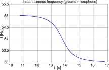
Recorded signals were later processed to test the Doppler Effect removing inethod described in [1], The described tested algorithm relies on the task oriented dynamie resampling of the recorded signal. The signal resampling was done according to the changes in the freąuency of the recorded signal from a moving source (a vehicle). As was proved in [1] a freąuency change of the pure tonę acoustic signal moving relatively to the microphone could be described with (Fig .4)
1 Vd Jtf+(s-Vz-tf
where:
• f0 - real freąuency of the signal source,
• fR - instantaneous freąuency of the recorded signal,
• Vd- sound yelocity in the air ( Vd = 343 m/s was
assumed),
• Vz -yelocity of the moving yehicle (signal source),
• h - distance from the microphone to the railway
track,
• s - distance describing the position of the yehicle
in the moment of signal recording beginning defined as a distance from the point closest to the microphone.
Having fixed f0 freąuency and fR(t) wavefonn one can resample the recorded signal using the new dt(l) according to the formula:
dU(t)=-f~
fR(t)
where dt is the sampling interval (inyerse of the sampling freąuency).
%
US MIC

5.85
US - ultrasound microphone, MIC - acoustic microphone MD -directional microphone,
0.150
Fig. 3. Sensor placement on a ground station used in the experiment.
On the pass-by ground station besides GPS PPS signal, acoustic pressure (noise) signals using five inicrophones (2 conventional measuring microphones, 2 ultrasonic and one directional microphone) were recorded. The distance between microphones group’s positions was selected according to the vehicle axle distance of 5,85m. Additionally the ground yibrations in two directions

Fig. 4. Change of instantaneous freąuency of 54 Hz according to eąuation 1.
Wyszukiwarka
Podobne podstrony:
Diagnostyka’ 4(48)/2008 DYBAŁA, GALĘZIA, MĄCZAK, I erificalion Of Doppler Effect Removal AleihodFor
Diagnostyka’ 4(48)/2008 DYBAŁA, GAŁĘZIĄ, MĄCZAK, Verification Of Doppler EffectRemovalMethodFor The
Diagnostyka’ 4(48)/2008 7 DYBAŁA, GALĘZIA, MĄC7.AK, Yerification Of Doppler Effect
Diagnostyka’ 4(48)/2008 KEKEZ, AMBROZIK, RADZISZEWSKI, Modeling of Cylinder Pres surę in Compression
10 Diagnostyka’ 4(48)/2008 KEKEZ, AMBROZIK, RADZISZEWSKI, Modeling of Cylinder Pre
12 Diagnostyka’ 4(48)/2008 KEKEZ, AMBROZIK, RADZISZEWSKI, Modeling of Cylinder Pre
14 Diagnostyka’ 4(48)/2008 KEKEZ, AMBROZIK, RADZISZEWSKI, Modeling of Cylinder Pre
16 Diagnostyka’ 4(48)/2008 KEKEZ, AMBROZIK, RADZISZEWSKI. Modeling of Cylinder Pre
Diagnostyka’ 4(48)/2008 11 KEKEZ, AMBROZIK, RADZISZEWSKI, Modeling of Cylinder Pre
Diagnostyka’ 4(48)/2008 13 KEKEZ, AMBROZIK, RADZISZEWSKI, Modeling of Cylinder Pre
Diagnostyka’ 4(48)/2008 15 KEKEZ, AMBROZIK, RADZISZEWSKI, Modeling of Cylinder Pre
17 Diagnostyka 4(48)/2008 BARSZCZ, MASKA, Application of Hardware-In-Loop for 11irtualPower
Diagnostyka 4(48)/2008 Spis treści / Contents Jubileuszprof. Lesława BĘDKOWSKIEGO / Jubilee of Profe
Diagnostyka 4(48)/2008 Spis treści/ Contents Jędrzej MĄCZAK - Politechnika
Diagnostyka’ 4(48)/2008 Jubileusz prof. Lesława BĘDKOWSKIEGO / Jubilee of Profesor Lesław
Diagnostyka’ 4(48)/2008 BARSZCZ, MAŃKA, Application ofHardware-In-Loop for 1 irlual Power Piani •
Diagnostyka’ l(45)/2008 RYBCZYŃSKI, Maps offolerable Misalignments of Bearings Applicable...MAPS OF
12 Diagnostyka’ l(45)/2008 RYBCZYŃSKI, Maps ofTolerable Misalignments of Bearings
14 Diagnostyka’ l(45)/2008 RYBCZYŃSKI, Maps ofTolerable Misalignmenls of Bearings
więcej podobnych podstron