7696082028
Clearly structured MIMO OTAtest plan
Two basie test cases are usually sufficient to character-ize true MIMO OTA performance. Each test case covers a practical extreme condition under aspects of real-world use of the UE implementation. Both test cases are directly related to the spatial properties of the UE antenna system. These two test cases are referred to in the following two sections as:
i Noise limited performance in transmit diversity modę, NLTD
i Peak performance in spatial multiplexing modę, PPSM
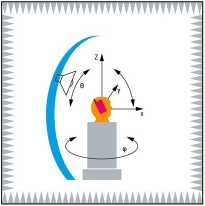
UE coordinate system for NLTD test case with one test antenna

Noise-limited OTA performance in transmit diversity modę (NLTD)
Downlink transmit diversity (TD) is the most likely trans-mission modę for LTE user equipment operated close to the celi edge. It ensures good link reliability and through-put. In this scenario, the downlink signal approaches the level of noise generated by the UE itself. The test case amounts to characterization of UE sensitivity in a noise-limited scenario using robust low-order (i.e. QPSK) modu-lation. It is similar to traditional total isotropic sensitivity (TIS) measurements for SISO devices.
Investigating UE sensitivity in a noise-limited scenario amounts to baseline performance characterization which covers the following physical implementation aspects: i Antenna efficiency i Receiver noise figurę i Self-interference
Test setup
The anechoic chamber is compatible with SISO OTA tests, including a dual-polarized test antenna. Two output ports from the R&S®CMW500 MIMO base station emulator are connected directly to the ports of the test antenna for the two polarizations. In the TD scheme, two orthogonal sig-nals are simultaneously routed to the two polarizations of the test antenna. The test antenna is moved across the surface of a sphere in space in a defined grid in order to access all relevant angles of arrival.
Test procedurę
The sensitivity threshold search usually decreases DL power while measuring the błock error ratę (BLER).
The effective isotropic sensitivity value (EIS) is reported for each test position for a BLER of e.g. 10%.
The measurement is repeated by repositioning the test antenna and rotating the UE until the sphere is completely sampled, using a predefined step size (e.g. 30°). This re-sults in 60 throughput measurements based on 60 con-stellations and one polarization case.
Set of geometrical constellations for NLTD test

(p 0°, 30°,... . 330° Azimuth position
(total of 12)
0 30°, 60°,.... 150° Elevation position of test antenna
(total of 5)
The step size may be changed and measurements can be limited to dedicated pattern areas in order to decrease the test time.
Wyszukiwarka
Podobne podstrony:
With regard to type of the functional and spatial structure, two basie kinds of centers can be
New test methods for MIMO OTA measurements Currently, OTA performance tests for single input si
Guaraniclla gen. n. Diagnosis : Eight clearly discernible eyes arranged in two rows, A-row rccurvcd,
Ciągła współpraca zespołu Backlofl2 Plan/Analysis45 D«v Test Done Technical Specs
00026 Cb73b0bebba97f943b5cdb88f01cf94 25 A Rule-Based Approach to Multiple Statistical Test Analysi
00353 [8365c31cc1dd1f95a44b8594b6530a 357 A Monitoring Plan for Detecting Product Degradation suffi
skanuj0016 Analiza ekonomiczna - przykładowy test • Współczynnik zdolności tworzen
NPL Report MATC(A) 164 6.3. 3-Point Bend Test In the 3-point bend test the force was applied to the
_a EWifeOLGPRS Performance - Performance evaluation • Three test environments are defined in order t
496 rences are illustrated by dala conceming the basie indicators Ihat are characteristic for the Po
mbs 065 MY BREATH ING SYSTEM exhalation comprise, each of them. two abdominal move-ments—four in all
208 PLAN KONTYNUACJI „BUDOWY ŚWIATA HISTORYCZNEGO” Myślenie dyskursywne reprezentuje to, co jest zaw
Shell Brooch Thesc two pieces of hcll just naturally seemcd to go together. The purple iris beads rc
12grupab1 LANGUAGE ANO SKILLS TEST 1 B UNITS 1-2USTENING SKILLS i Listen to Cathy introducing hersel
więcej podobnych podstron