7884079561
NPL Report MATC(A) 164
6.3. 3-Point Bend Test
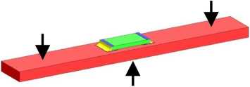
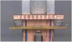
In the 3-point bend test the force was applied to the substrate on the side opposite to that of the resistor (see Figures 16 and 17), and the substrate deformation was monitored and measured at the top of the resistor body. The extent of the deformation depends on the force exerted on the resistor through the solder joint.

Figurę 16. Schcmatic of the 3-point bend test.

Figurę 17. The 3-point bend testing jig.
In Figurę 18 the strain gauge measurements of deformation are plotted as a function of the assembly displacement at the mid point between the resistor's soldered joints. The test specimens had been soldered using SnAgCu alloy and had not been subjected to any thermal cycling. This exercise was carried out to investigate the variation of deformation with time afler 20 pm displacement steps, each with a dwell time of 10 seconds. The individual displacements are shown along the horizontal axis, whilst the vertical steps represent the amounts of time-dependent deformation after each displacement step. It is elear that after a displacement of only 60 pm the curve takes a step-like shape, indicating a drift in deformation i.e. a time-dependent (creep) behaviour during the 10 seconds dwell period. It follows that irrespective of the thermal cycling
12
Wyszukiwarka
Podobne podstrony:
NPL Report MATC(A) 164 Figurę 12. Test arrangements of resistor specimen. Figurę 13. Predicted major
NPL Report MATC(A) 164 Figurę 5. Central scctioning point shows the microstructurc, but not dcvclopi
NPL Report MATC(A) 164 Cracked area Figurę 6. Crack in a SnAgCu soldcr joint after thcrmal cycling.
NPL Report MATC(A) 164 Finał polishing of the samples was carried out by hand using a gamma aluminid
NPL Report MATC(A) 164 6. Mechanical Tests Mechanical tests were used to investigate the time-depend
NPL Report MATC(A) 164 The following steps were carried out: • The substratc was c
NPL Report MATC(A) 164 0
NPL Report MATC(A) 164 regime used, the solder becomes accommodating and. irreversible plastic defor
NPL Report MATC(A) 164 curves coincide for displacements less than ~125 pm. For higher levels of dis
NPL Report MATC(A) 164 simulate this “worst case” scenario, 2512-type chip resistors and FR4 substra
NPL Report MATC(A) 164 Table 1: Tested temperaturę cycling regimes within ± 4°C of the set
więcej podobnych podstron