7884079564
NPL Report MATC(A) 164
curves coincide for displacements less than ~125 pm. For higher levels of displacement the two curves diverge, and this is attributed to the simplicity of the model. Similar comparisons were madę following other tests on specimens subjected to a rangę of thermal cycles, with similar results.
6.4. 4-Point Bent Test
The 4-point bend test is an altemative to the 3-point bend test, with the solder joints stressed in the opposite direction to that used in the 3-point test. Figurę 20 illustrates the layout and the direction of the forces on the assembly. The FE A model calculations were promising (see Figurę 21), with a elear relationship showing the influence on the crack length of a theoretical compressive strain on the top-side of the resistor. However, this testing method was rejected as the simulation also highlighted that the practical test would cause further propagation of the cracks and a conseąuential peeling of the remaining solder joint, as illustrated schematically in Figurę 22.
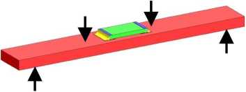
Figurę 20. Test spccimcn with forccs (arrows) acting in 4-point bend test.
=; 60
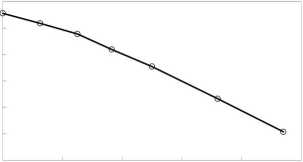
0.1 0.2 0.3 0.4 0.5
Crack length [mm]
Figurę 21. Model calculations of the impact of compressivc strain on crack length.
14
Wyszukiwarka
Podobne podstrony:
NPL Report MATC(A) 164 Finał polishing of the samples was carried out by hand using a gamma aluminid
NPL Report MATC(A) 164 Figurę 5. Central scctioning point shows the microstructurc, but not dcvclopi
NPL Report MATC(A) 164 Cracked area Figurę 6. Crack in a SnAgCu soldcr joint after thcrmal cycling.
NPL Report MATC(A) 164 6. Mechanical Tests Mechanical tests were used to investigate the time-depend
NPL Report MATC(A) 164 The following steps were carried out: • The substratc was c
NPL Report MATC(A) 164 Figurę 12. Test arrangements of resistor specimen. Figurę 13. Predicted major
NPL Report MATC(A) 164 0
NPL Report MATC(A) 164 6.3. 3-Point Bend Test In the 3-point bend test the force was applied to the
NPL Report MATC(A) 164 regime used, the solder becomes accommodating and. irreversible plastic defor
NPL Report MATC(A) 164Crack Detection Methods for Lead-free Solder Joints Milos Duśek and Christophe
NPL Report MATC(A) 164 simulate this “worst case” scenario, 2512-type chip resistors and FR4 substra
NPL Report MATC(A) 164 Table 1: Tested temperaturę cycling regimes within ± 4°C of the set
więcej podobnych podstron