7884079555
NPL Report MATC(A) 164
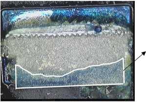
Cracked area
Figurę 6. Crack in a SnAgCu soldcr joint after thcrmal cycling.
The crack area growth in terms of the number of cycles was evaluated by measuring the number of pixels in the appropriate part of the image, and the results are presented in Figurę 7. Since this method gives morę quantitative results than does micro-sectioning, it can be used for assessment of non-cracked area i.e. to study the stress acting on a solder joint, and to analyze the whole area of a crack. It is not dependent on the positioning of the cross-sectional piane, as is the case with micro-sectioning.

Figurę 7. Percentage of cracked area under 2512-type resistors as a function of the number of thcrmal cycles, for SnAgCu soldcr
Wyszukiwarka
Podobne podstrony:
NPL Report MATC(A) 164 Figurę 5. Central scctioning point shows the microstructurc, but not dcvclopi
NPL Report MATC(A) 164 Figurę 12. Test arrangements of resistor specimen. Figurę 13. Predicted major
NPL Report MATC(A) 164 Finał polishing of the samples was carried out by hand using a gamma aluminid
NPL Report MATC(A) 164 6. Mechanical Tests Mechanical tests were used to investigate the time-depend
NPL Report MATC(A) 164 The following steps were carried out: • The substratc was c
NPL Report MATC(A) 164 0
NPL Report MATC(A) 164 6.3. 3-Point Bend Test In the 3-point bend test the force was applied to the
NPL Report MATC(A) 164 regime used, the solder becomes accommodating and. irreversible plastic defor
NPL Report MATC(A) 164 curves coincide for displacements less than ~125 pm. For higher levels of dis
NPL Report MATC(A) 164 simulate this “worst case” scenario, 2512-type chip resistors and FR4 substra
NPL Report MATC(A) 164 Table 1: Tested temperaturę cycling regimes within ± 4°C of the set
więcej podobnych podstron