7884079570
NPL Report MATC(A) 164
simulate this “worst case” scenario, 2512-type chip resistors and FR4 substrates with the ENIG (immersion gold over electroless nickel) finish were used in this study. They are lead-free, in common usage, and widely available. The PCB assemblies used, illustrated in Figurę 2, were fabricated from single-sided FR4 boards (thickness 1.6 mm) with a copper thickness of 35 pm (copper plating 1 oz/sq.ft) and an ENIG board finish.
ca
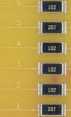
Figurę 2. FR4 laminatc with 2512-type resistors used in the crack asscssmcnt study.
The substrates were stencil printed with solder pastę using a stainless Steel stencil with a thickness of 150 pm (0.006”). The components were placed onto the substrates using an automatic placement system, and the lead-free solder alloys used were 95.5Sn3.8Ag0.7Cu and 96.5Sn3.5Ag in no-clean solder pastę compositions. These processes ensured a consistent solder joint Yolume. Reflow of the solder pastę was achieved in a convection reflow oven - the reflow temperaturę profiles are described in delail elsewhere [2], 3. Thermal Cycling
The traditional acceleration method of generating cracks in solder joints is to subject the assemblies [3] to thermal cycling regimes, during which the cracks are caused by stresses exceeding the ultimate shear stress of the particular solder alloy. The localised stresses can be caused mechanically, by materiał displacement, or by mismatch of the coefficients of thermal expansion (CTE) of the two joined materials exposed to temperaturę changes. In the electronic assemblies used here there were mismatches in CTE between the component body (alumina 6.5ppm/°C), the solder (21-25ppm/°C), the copper termination pad (17.6ppm/°C) and the FR4 laminate (CTE^, = 12-18ppm/°C, CTE/ = 50ppm/°C). In addition, all these coefficients vary with temperaturę. The largest mismatch over the longest absolute dimension is between the component body and the FR4 substrate [4], The parameters of the thermal cycling regime used in this evaluation study are listed in Table 1, and Figurę 3 shows a graphical representation of a thermal cycle.
2
Wyszukiwarka
Podobne podstrony:
NPL Report MATC(A) 164 Finał polishing of the samples was carried out by hand using a gamma aluminid
NPL Report MATC(A) 164 Figurę 5. Central scctioning point shows the microstructurc, but not dcvclopi
NPL Report MATC(A) 164 Cracked area Figurę 6. Crack in a SnAgCu soldcr joint after thcrmal cycling.
NPL Report MATC(A) 164 6. Mechanical Tests Mechanical tests were used to investigate the time-depend
NPL Report MATC(A) 164 The following steps were carried out: • The substratc was c
NPL Report MATC(A) 164 Figurę 12. Test arrangements of resistor specimen. Figurę 13. Predicted major
NPL Report MATC(A) 164 0
NPL Report MATC(A) 164 6.3. 3-Point Bend Test In the 3-point bend test the force was applied to the
NPL Report MATC(A) 164 regime used, the solder becomes accommodating and. irreversible plastic defor
NPL Report MATC(A) 164 curves coincide for displacements less than ~125 pm. For higher levels of dis
NPL Report MATC(A) 164 Table 1: Tested temperaturę cycling regimes within ± 4°C of the set
więcej podobnych podstron