7884079559
NPL Report MATC(A) 164
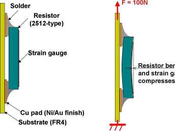
Figurę 12. Test arrangements of resistor specimen.
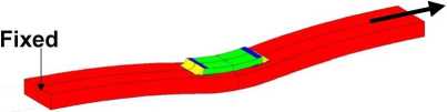
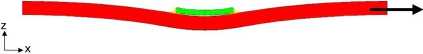
Figurę 13. Predicted major bend modę.
The measurements indicate that the solder joint integrity goes through a deterioration phase, and that the top of the resistor is subjected to smaller compression stresses after a high number of cycles.
10
Wyszukiwarka
Podobne podstrony:
NPL Report MATC(A) 164 Figurę 5. Central scctioning point shows the microstructurc, but not dcvclopi
NPL Report MATC(A) 164 Cracked area Figurę 6. Crack in a SnAgCu soldcr joint after thcrmal cycling.
NPL Report MATC(A) 164 6.3. 3-Point Bend Test In the 3-point bend test the force was applied to the
NPL Report MATC(A) 164 Finał polishing of the samples was carried out by hand using a gamma aluminid
NPL Report MATC(A) 164 6. Mechanical Tests Mechanical tests were used to investigate the time-depend
NPL Report MATC(A) 164 The following steps were carried out: • The substratc was c
NPL Report MATC(A) 164 0
NPL Report MATC(A) 164 regime used, the solder becomes accommodating and. irreversible plastic defor
NPL Report MATC(A) 164 curves coincide for displacements less than ~125 pm. For higher levels of dis
NPL Report MATC(A) 164 simulate this “worst case” scenario, 2512-type chip resistors and FR4 substra
NPL Report MATC(A) 164 Table 1: Tested temperaturę cycling regimes within ± 4°C of the set
więcej podobnych podstron