7884079554
NPL Report MATC(A) 164
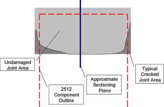
Figurę 5. Central scctioning point shows the microstructurc, but not dcvcloping corner cracks.
It should be noted that whilst the micro-sectioning techniąue is suitable for the assessment of the failure modę, it can be misleading for quantitative evaluation of crack growth in the solder joints. This is illustrated in Figurę 5, which shows the location of cracked joint areas with reference to a mid piane between the ends of the component. If the latter happens to be the cross-sectional piane nonę of the cracked area would be visible in the microsection. Hence to ensure crack detection the cross-sectional piane should be close to the component outline. Unfortunately with smali component sizes, such as 0805-type resistors, this may be difficult to achieve.
5. Dye Penetration
Dye penetration is another destructive techniąue used for studying the location and extent of cracking. In this study the dye penetration test was performed on the 2512-type resistor joints after thermal cycling. The assemblies were cleaned in an ultrasonic bath in a solution of 50% water, 50% iso-propyl alcohol. After drying the assemblies using compressed air, they were inserted into a vacuum beli and immersed in Rocol Layout Ink Fluid (red or blue) dye. A partial vacuum was applied for 15 min. The dye was cured on the assemblies by baking in a convection oven at 50°C for 10 minutes. The components were then removed by twisting with pliers, and the joints inspected for dye penetration using an optical microscope. A typical image is presented in Figurę 6, in which the white linę highlights the cracked area.
5
Wyszukiwarka
Podobne podstrony:
NPL Report MATC(A) 164 Figurę 12. Test arrangements of resistor specimen. Figurę 13. Predicted major
NPL Report MATC(A) 164 Cracked area Figurę 6. Crack in a SnAgCu soldcr joint after thcrmal cycling.
NPL Report MATC(A) 164 6.3. 3-Point Bend Test In the 3-point bend test the force was applied to the
NPL Report MATC(A) 164 Finał polishing of the samples was carried out by hand using a gamma aluminid
NPL Report MATC(A) 164 6. Mechanical Tests Mechanical tests were used to investigate the time-depend
NPL Report MATC(A) 164 The following steps were carried out: • The substratc was c
NPL Report MATC(A) 164 0
NPL Report MATC(A) 164 regime used, the solder becomes accommodating and. irreversible plastic defor
NPL Report MATC(A) 164 curves coincide for displacements less than ~125 pm. For higher levels of dis
NPL Report MATC(A) 164 simulate this “worst case” scenario, 2512-type chip resistors and FR4 substra
NPL Report MATC(A) 164 Table 1: Tested temperaturę cycling regimes within ± 4°C of the set
więcej podobnych podstron