1
INTRODUCTION
GENERAL
This section has the instructions for the disassembly and
assembly of the four stage mast for 2000–3000 kg
(4000–6000 lb) models of lift trucks. The checks and ad-
justments are described at the end of this section. Addi-
tional information for the repair of the hydraulic cylin-
ders can be found in the following sections:
LIFT CYLINDERS, 4000 SRM 135
THE TILT CYLINDERS, 2100 SRM 103
WARNING
The crane, slings, and chains used to lift assemblies
in this section must have a minimum capacity of 2000
kg (4000 lb).
REPAIRS
WARNING
Before working on or near the mast, read SAFETY
PROCEDURES WHEN WORKING NEAR THE
MAST. See FIGURE 2.
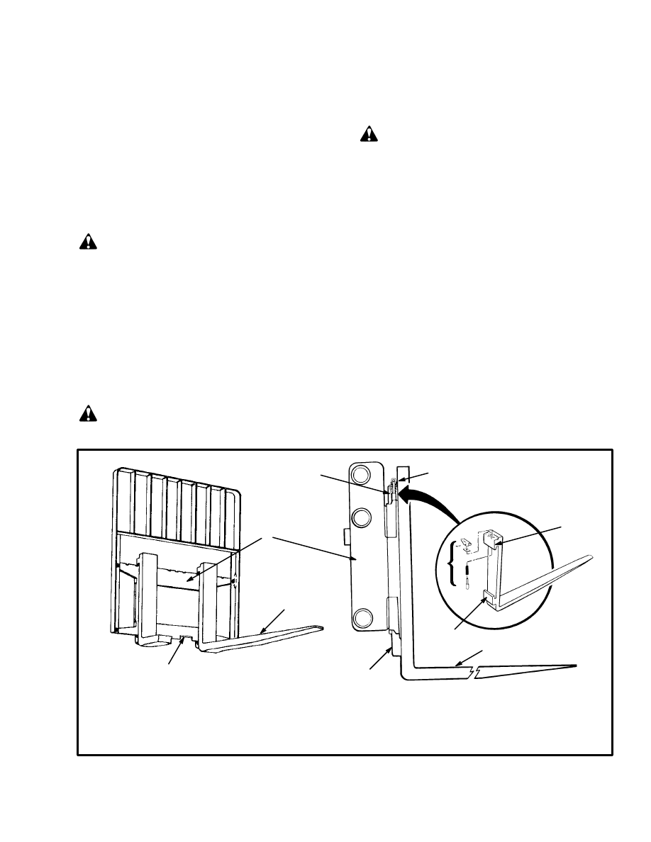
FORKS (See FIGURE 1. and FIGURE 3.)
Hook forks are connected to the carriage by hooks and
locking pins. These pins fit through the top of the fork
hooks and into slots on the top carriage bar. Align the
forks with the fork removal notch in the bottom carriage
bar to remove the forks from the carriage.
WARNING
Use a lifting device to lift the forks when they are re-
moved from the carriage.
CARRIAGE (See FIGURE 1.)
Removal
The carriage must be removed through the top of the in-
ner weldment. If only the carriage must be removed
from the mast for repairs, use these instructions to re-
move the carriage. If the mast must be removed from the
lift truck for repairs, the carriage and mast can be re-
moved from the lift truck as a unit.
1. Lower the carriage onto blocks so that the tension is
removed from the lift chains.
2. Remove the forks from the carriage.
FIGURE 1. HOOK FORKS
1. FORK REMOVAL NOTCH
2. FORK
3. HOOK
4. LOCK PIN ASSEMBLY
5. CARRIAGE
10221
1545
1
2
5
3
4
3
4
2
3
3
2
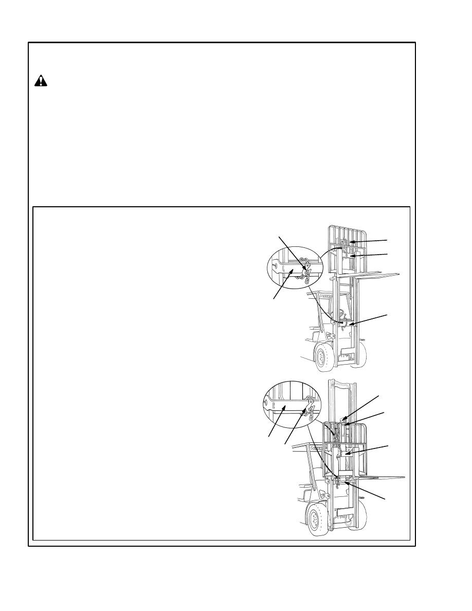
SAFETY PROCEDURES WHEN WORKING NEAR THE MAST (1 of 2)
Mast parts are heavy and can move. Distances between parts are small. Serious injury or death can
result if part of the body is hit by parts of the mast or the carriage.
•
Never put any part of the body into or under the mast or carriage unless all parts are
completely lowered or a safety chain is installed. Also make sure that the power is off and the
key is removed. Put a “DO NOT OPERATE” tag in the operator’s compartment. Disconnect the
battery and put a tag or lock on the battery connector.
•
Be careful of the forks. When the mast is raised, the forks can be at a height to cause an injury.
•
DO NOT climb on the mast or lift truck at any time. Use a ladder or personnel lift to work on
the mast.
•
DO NOT use blocks to support the mast weldments nor to restrain their movement.
•
Mast repairs require disassembly and removal of parts and can require removal of the mast
or carriage. Follow the repair procedures in the this section.
WHEN WORKING NEAR THE MAST ALWAYS:
•
Lower the mast and carriage completely. Push the lift/lower
control lever forward and make sure there is no movement in
the mast. Make sure that all parts of the mast that move are
fully lowered.
OR
•
If parts of the mast must be in a raised position, install a
safety chain to restrain the moving parts of the mast. Connect
moving parts to a part that does not move. Follow these pro-
cedures:
a. Put the mast in a vertical position.
b. Raise the mast to align the bottom crossmember of the weld-
ment that moves in the outer weldment with a crossmember on
the outer weldment (1). On the LFL and FFL units, the moving
part is the inner weldment (2). On the three–stage it is the inter-
mediate weldment (3). On the four–stage it is the first intermedi-
ate weldment.
c. Use a 3/8 inch minimum safety chain with a hook (5) to fasten
the cross members together so that the movable member can
not lower. Put the hook on the back side of the mast. Make sure
the hook is completely engaged with a link in the chain. Make
sure the safety chain does not touch lift chains or chain sheaves,
tubes, hoses, fittings, or other parts on the mast.
d. Lower the mast until there is tension in the safety chain and
the free–lift cylinder (6) (FFL, three–stage and four–stage) is
completely retracted. If running, turn the power OFF. Apply the
parking brake. Install a “DO NOT REMOVE” tag on the safety
chain(s).
e. Install another safety chain (3/8 inch minimum) between the
top or bottom crossmember of the carriage (7) and a crossmem-
ber on the outer weldment (8).
•
Apply the parking brake. After lowering or restraining the
mast, shut off the power and remove the key. Put a “DO NOT
OPERATE” tag in the operator’s compartment. Disconnect
the battery and put a tag or lock on the battery connector.
1
2
5
8
The following procedures must be used when inspecting or working near the mast. Additional precautions
and procedures can be required when repairing or removing the mast.
LFL
FFL
7
8
5
1
2
7
6
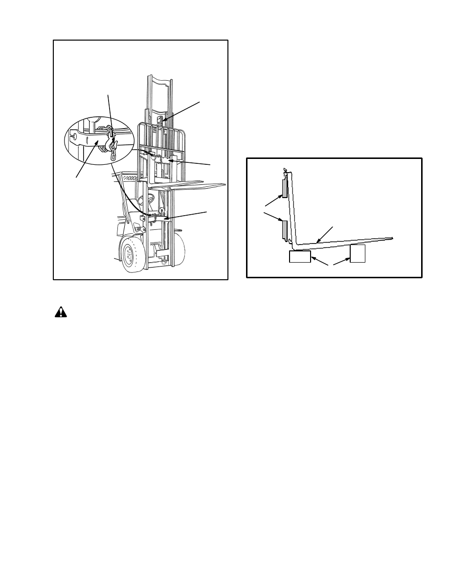
FIGURE 2. SAFETY PROCEDURES WHEN WORKING NEAR THE MAST (1 of 2)
WARNING
3
SAFETY PROCEDURES WHEN
WORKING NEAR THE MAST
3
7
6
THREE–STAGE,
FOUR–STAGE
1
5
FIGURE 2. SAFETY PROCEDURES WHEN
WORKING NEAR THE MAST (2 of 2)
WARNING
When the lift chains are disconnected, keep control
of the ends of the chains. If the chains are not con-
trolled, they can run through the sheaves, fall from
the top of the mast and cause injury and damage.
3. Remove the two carriage stops from the top of the in-
ner weldment.
4. Disconnect the lift chains from the chain anchors on
the free–lift cylinder. Remove the chains from the
sheaves on the crosshead assembly of the free–lift cylin-
der.
NOTE: The lift chains can be disconnected from the
carriage instead of the lift cylinder. Many service people
disconnect the lift chains from the lift cylinder because
access to the chain anchors is easier.
5. If the lift truck is equipped with a side shift carriage,
disconnect the hydraulic lines at the carriage. Install a
cap on each open fitting.
6. Connect the lifting device with a capacity of 2000 kg
(4000 lb) to the top of the carriage. Make sure the chain
or sling will not damage the sheaves or other parts when
the carriage is lifted.
7. Carefully lift the carriage until the load rollers are
above the inner weldment of the mast. Move the car-
riage to the place where repairs will be done.
8. If a carriage load roller must be replaced, make a note
of the shim arrangement. When the load rollers are as-
sembled again, install a similar shim arrangement and
check the clearance.
ÉÉÉ
ÉÉÉ
ÉÉ
ÉÉ
ÉÉ
FIGURE 3. REMOVE THE FORKS
1. CARRIAGE BARS
2. HOOK FORK
3. BLOCKS
1
2
3
Installation
1. Make sure that the carriage assembly and load rollers
are ready for installation. Connect the lifting device to
the top of the carriage. Raise the carriage with the lifting
device so that the load rollers can engage the inner weld-
ment.
2. Check the clearance of the load rollers in the inner
weldment. See the CARRIAGE ADJUSTMENT proce-
dure at the end of this section. If adjustments must be
made to the load rollers, remove the carriage from the
mast and make the adjustments. Then install the carriage
in the mast again.
3. Lower the carriage onto blocks so that the lift chains
can be installed. Install the lift chains. Adjust the length
of the lift chains. See LIFT CHAIN ADJUSTMENTS
at the end of this section. Install new cotter pins in the
chain anchors.
4. Connect the hydraulic lines if the carriage has a hy-
draulic attachment.
5. Install the two carriage stops at the top of the inner
weldment. Install the forks on the carriage.
4
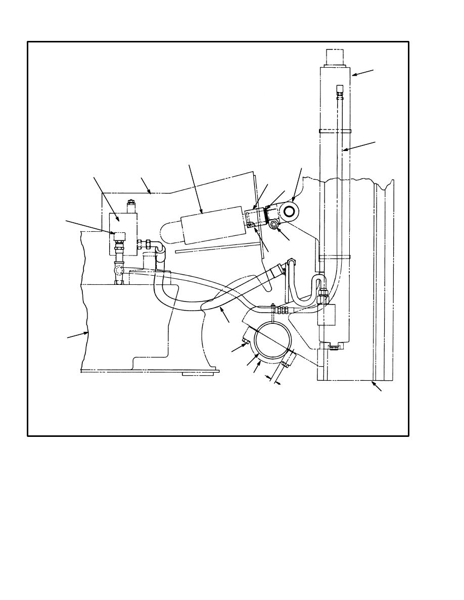
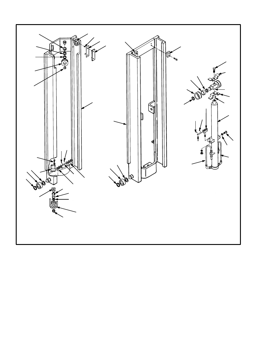
FIGURE 4. MAST MOUNT
1. MAST
2. MAIN LIFT CYLINDER
3. DRAIN HOSE
4. TAB (BETWEEN BEARING HALVES
PREVENTS ROTATION OF BUSHINGS)
5. PIVOT CAP
6. BUSHING (2)
7. HYDRAULIC SUPPLY HOSE
8. HYDRAULIC TANK
9. BREATHER
2
10. MAIN CONTROL VALVE
11. TILT CYLINDER
12. FRAME
13. O–RING
14. TILT LIMIT SPACER
15. SHIMS
16. CAPSCREW (TIGHTEN TO 90 Nm/66lb
f
ft) TORQUE
17. END OF ROD
18. CAPSCREW (165Nm/122 lb
f
ft) TORQUE
11625
J2.00–3.00XL (J40–60XL) SHOWN
OTHERS ARE SIMILAR.
5
9
2
6
18
4
1
10
12
11
8
3
17
15
14
7
13
16
MAST
Removal (See FIGURE 4.)
NOTE: The carriage must be removed through the top
of the inner weldment. If the mast must be removed
from the lift truck for repairs, the carriage and mast can
be removed from the lift truck as a unit.
1. If the mast must be removed from the lift truck for dis-
assembly and repair of worn parts, inspect the lift chains
before the mast is removed from the lift truck. Inspect
the lift chains for cracks or broken links and pins. Check
for corrosion or worn holes in the links. When the pins
or the holes wear, the chain becomes longer. The chain
links that run over the chain sheaves have the most wear.
If a chain is 3% longer than a new chain, the chain is

5
worn and must be replaced. If a chain scale is available,
check the lift chains as shown in Figure 7. If a chain
scale is not available, measure 20 links of chain. Com-
pare the length with the chart. Replace the chain if the
length of 20 links of the worn chain is more than the
wear limit.
WARNING
When the lift chains are disconnected, keep control
of the ends of the chains. If the chains are not con-
trolled, they can run through the sheaves, fall from
the top of the mast and cause injury and damage.
Replace a worn chain. Do not repair a worn chain. If
one chain in a pair of chains is worn or damaged, re-
place both chains.
2. Fully lower the mast. Remove the forks from the car-
riage.
3. Clean the area next to the fittings that connect the hy-
draulic hose to the main lift cylinder. Put a drain pan un-
der the area where the lines are disconnected. Discon-
nect the hydraulic lines and put a cap on each open
fitting.
4. Use chains to connect a 2000 kg (4000 lb) capacity
lifting device to the top of the mast. Use a chain to fasten
all of the mast weldments together so that they can not
move. Make sure the chains will not damage the sheaves
or other parts of the mast assembly. Raise the lifting de-
vice until it holds the weight of the mast. Put the lifting
device in position so that the mast will be lifted vertical-
ly.
WARNING
DO NOT use your fingers to push the connecting
pins from the clevis of the tilt cylinders. Use a driver.
5. Disconnect the tilt cylinders at the mast. Do not cause
damage to the piston rods by letting them fall on the
edge of the cowl.
6. Make an identification mark on the pivot caps so that
they will be installed again in the same position. Make
sure the mast assembly will not move suddenly when the
pivot caps are removed. Remove the pivot caps. See the
mast mounts in FIGURE 4.
7. Carefully lift the mast assembly away from the lift
truck. Make sure all of the cables and hoses are discon-
nected.
8. Put the mast assembly on blocks so that the back of
the mast is towards the floor.
Disassembly
(See FIGURE 5. and FIGURE 6.)
The following instructions are for the complete disas-
sembly of the mast AFTER the mast has been removed.
See MAST Removal. Disassemble the mast only as nec-
essary to make repairs.
1. Remove the two carriage stops from the top of the in-
ner weldment.
2. Disconnect the lift chains from the chain anchors on
the free–lift cylinder. Remove the chains from the
sheaves on the crosshead assembly of the free–lift cylin-
der.
NOTE: The lift chains can be disconnected from the
carriage instead of the lift cylinder. Many service people
disconnect the lift chains from the lift cylinder because
access to the chain anchors is easier.
3. If the lift truck is equipped with a side shift carriage,
disconnect the hydraulic lines at the carriage. Install a
cap on each open fitting.
4. Connect the 2000 kg (4000 lb) capacity lifting device
to the top of the carriage. Make sure the chain or sling
will not damage the sheaves or other parts when the car-
riage is lifted.
5. Carefully move the carriage to the top of the inner
weldment. Use the lifting device to hold the weight of
the carriage until the load rollers are disengaged from
the inner weldment of the mast. Move the carriage to the
place where repairs will be done.
6. If a carriage load roller must be replaced, make a note
of the shim arrangement. When the load rollers are as-
sembled again, install a similar shim arrangement and
check the clearance.
7. Use a sling to connect a lifting device to the free–lift
cylinder.
8. Disconnect the tube assemblies and the hose assem-
blies from both cylinders. Install a cap on each open fit-
ting.
9. Remove the capscrews that hold the free–lift cylinder
to the sides of the inner weldment.
10. Raise the free–lift cylinder with the lifting device
and move it away from the mast assembly. Disassemble
the crosshead assembly or the free–lift cylinder as nec-
essary to make repairs.
6
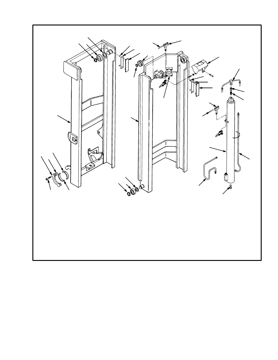
1. SECOND INTERMEDIATE
WELDMENT
2. STRIP BEARING
3. SHIM
4. O–RING
5. L0AD ROLLER
6. SNAP RING
7. SPACER
8. CHAIN SHEAVE
9. HOSE SHEAVE MOUNT
10. CAPSCREW AND WASHER (8)
11. CHAIN ANCHOR
12. COTTER PIN
13. ANCHOR PIN
14. INNER WELDMENT
15. HOSE SHEAVE
16. CARRIAGE STOP
17. TUBE ASSEMBLY
18. FREE–LIFT CYLINDER
19. PIN
20. CHAIN KEEPER
21. CAPSCREW
22. CROSS SHAFT
FIGURE 5. FOUR–STAGE MAST, SECOND INTERMEDIATE AND INNER WELDMENTS
6
11627
5
1
2
7
6
8
6
4
3
12
12
13
11
11
10
9
7
5
6
6
15
6
7
6
9
7
5
6
14
16
16
21
6
7
8
6
12
12
13
11
18
22
7
17
17
19
20
20
22
NOTE: The inner weldment can be removed without
removing the main lift cylinder. The main lift cylinder is
connected to the top of the first intermediate weldment
and must have a support if the first intermediate weld-
ment is removed.
11. Connect a sling and lifting device to the main lift cyl-
inder.
12. Disconnect the lift cylinder from the top cross–
member of the first intermediate weldment. Disconnect
the lift cylinder from the bottom crossmember of the
outer weldment.
13. Lift the main lift cylinder away from the mast weld-
ments.
14. Remove the lift chains between the inner weldment
and the first intermediate weldment. Remove the chain
sheaves from the stub shaft on the second intermediate
weldment so that there is clearance for the inner weld-
ment to move past the second intermediate weldment.
7
17. FIRST INTERMEDIATE
WELDMENT
18. TUBE ASSEMBLY
19. SPECIAL TUBE FITTING
20. LOWERING CONTROL VALVE
21. MAIN LIFT CYLINDER
22. HOSE ASSEMBLY
23. TUBE ASSEMBLY
24. HOSE ANCHOR
FIGURE 6. FOUR–STAGE MAST, FIRST INTERMEDIATE AND OUTER WELDMENTS
1. OUTER WELDMENT
2. CAPSCREW
3. PIVOT CAP
4. TAB
5. BUSHING
6. SNAP RING
7. LOAD ROLLER
8. SPACER
11626
9. STRIP BEARING
10. SHIM
11. 0–RING
12. CHAIN SHEAVE
13. NUT AND WASHER
14. CHAIN KEEPER
15. ANCHOR PIN
16. CHAIN ANCHOR
8
7
6
5
13
16
9
11
10
8
7
6
1
5
4
3
2
12
6
15
14
11
10
9
18
20
19
22
16
2
23
13
15
17
21
24
15. Slide the inner weldment until the bottom load roll-
ers are in the removal slot at the top of the second inter-
mediate weldment. Use a lifting device to lift the inner
weldment. Lift the inner weldment away from the sec-
ond intermediate weldment.
NOTE: There are strip bearings and shims between
each weldment and the next weldment. The strip bear-
ings are behind the top load rollers in each channel.
These strip bearings and the shims under them control
the clearance between the tops of the weldments. The
strip bearings are held in the weldments with O–rings on
two studs. If the strip bearings are removed, make a note
of the shim arrangement so that the strip bearings will be
installed again in their original arrangement.
16. Disconnect the mounts for the hose sheaves from the
bottom of the second intermediate weldment. The hose
sheaves must be moved so that there is clearance to slide
the second intermediate weldment past the first interme-
8
diate weldment. If the hoses will be removed, remove
the hose anchor from the top of the intermediate weld-
ment.
17. Disconnect the lift chains from the bottom of the sec-
ond intermediate weldment.
18. Slide the second intermediate weldment until the
bottom load rollers are in the removal slots at the top of
the first intermediate weldment. Use a lifting device to
lift the second intermediate weldment. Lift the second
intermediate weldment away from the first intermediate
weldment.
19. Remove the lift chains from over the chain sheaves.
Slide the first intermediate weldment until the bottom
load rollers in the removal slots at the top of the outer
weldment. Use a lifting device to lift the first intermedi-
ate weldment. Lift the first intermediate weldment away
from the outer weldment.
20. Disconnect the lift chains from the chain anchors on
the outer weldment. Disassemble the sheaves and roll-
ers as necessary for repair and cleaning.
Cleaning
1. Do NOT use steam to clean the lift chains, sheaves or
load rollers. The sheaves and roller bearings are sealed
and permanently lubricated. Do not wash the lubricant
from the bearings. Replace rollers and sheaves that roll
rough or are damaged.
2. Wash the lift chains with solvent. Use compressed air
to dry the chains.
3. Clean the mast weldments with steam or solvent.
Inspection, Forks, Mast, And Lift Chains
(See FIGURE 7. and FIGURE 8.)
NOTE: Use this inspection procedure for assembled or
disassembled assemblies.
WARNING
Before working on or near the mast, read SAFETY
PROCEDURES WHEN WORKING NEAR THE
MAST. See FIGURE 2.
During the test procedures for the mast, use chains to
fasten the load to the carriage to prevent it from fal-
ling. Keep all people away from the lift truck during
the tests.
Never allow anyone under a raised carriage. Do not
put any part of your body in or through the lift
mechanism unless all parts of the mast are com-
pletely lowered and the power is OFF.
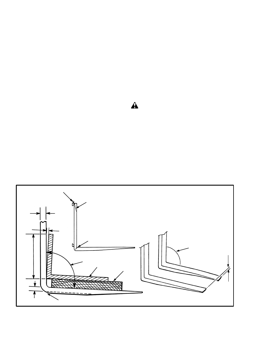
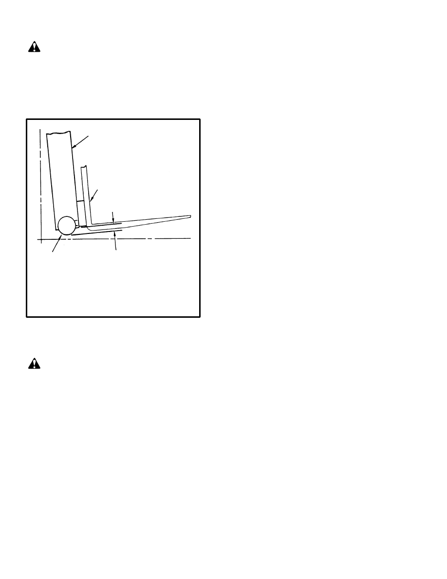
460 mm
(18 in)
24 mm
FIGURE 7. CHECK THE FORKS
6076
2
1. TIP ALIGNMENT
2. CRACKS
3. SQUARE
4. WOOD BLOCK
8
X
7
5
3
4
7
1
6
2
8562
5. HEEL OF FORK MUST BE
90% OF DIMENSION “X”
6. HEEL WEAR
7. 93
°
MAXIMUM ANGLE
8. LATCH DEFECTS
(0.94 in)
9
WARNING
Do not try to correct the alignment of the fork tips by
bending the forks or adding shims. Replace dam-
aged forks.
Never repair damaged forks by heating or welding.
Forks are made of special steel using special proce-
dures. Replace damaged forks.
1. Inspect the welds on the mast and carriage for cracks.
Make sure that the capscrews and nuts are tight.
2. Inspect the channels for wear in the areas where the
rollers travel. Inspect the rollers for wear or damage.
3. Inspect the load backrest extension for cracks and
damage.
4. Inspect the forks for cracks and wear. Check that the
fork tips are aligned within 13 mm (0.5 in) of each other.
Check that the bottom of the fork is not worn (item 6,
FIGURE 7.).
5. Replace any damaged or broken parts that are used to
keep the forks locked in position.
6. If the lift truck is equipped with a side–shift carriage
or attachment, inspect the parts for cracks and wear.
Make sure the parts that fasten the side–shift carriage or
attachment to the carriage are in good condition.
7. Check that the lift chains are correctly lubricated. Use
SAE 30 engine oil to lubricate the lift chains.
8. Inspect the lift chains for cracks or broken links and
pins.
9. Inspect the chain anchors and pins for cracks and
damage.
10. Make sure the lift chains are adjusted so that they
have equal tension. Adjustment or replacement of the
lift chains must be done by authorized personnel. See
Lift Chain Adjustments described in CHECKS AND
ADJUSTMENTS later in this section.
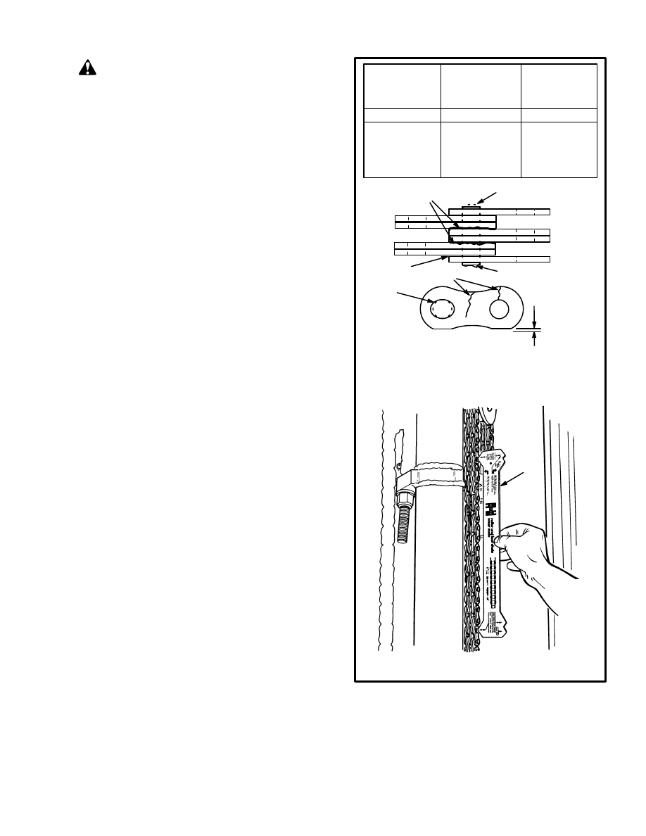
NOTE: The instructions for measuring chain
wear are shown on the Chain Wear Scale.
(inch)
mm
(inch)
mm
(inch)
mm
12.7
15.9
19.1
25.4
31.8
(0.50)
(0.625)
(0.75)
(1.00)
(1.25)
254.0
317.5
381.0
508.0
635.0
(10.0)
(12.5)
(15.0)
(20.0)
(25.0)
261.6
327.0
392.4
523.25
654.1
(10.3)
(12.88)
(15.45)
(20.6)
(25.75)
FIGURE 8. CHECK THE LIFT CHAINS
1. WORN PIN
2. CRACKS
3. EDGE WEAR
4. HOLE WEAR
5. LOOSE LEAVES
6. DAMAGED PIN
7. CORROSION
8. CHAIN WEAR SCALE
12174
2
6705
4
3
6
5
7
1
Pitch
Total length of 20
links (pitch) of
new chain
WEAR LIMIT
The maximum
length of 20 links
8
Assembly, Mast Components
(See FIGURE 5. and FIGURE 6.)
NOTE: On all models, the load rollers have shims to
keep the weldments parallel and give the correct clear-

10
ance. During assembly, the shim arrangement will be
the same or approximately the same arrangement as be-
fore disassembly. Check the clearance to adjust for wear
or changes because of repairs. The strip bearings found
on the top of the outer weldment are also adjusted with
shims. See the CHECKS AND ADJUSTMENTS in this
section for the instructions to make the necessary adjust-
ments.
1. Install the strip bearings and the approximate shim ar-
rangement on the outer weldment.
2. If the load rollers were removed, install the load roll-
ers and the approximate shim arrangement on both sets
of load rollers.
3. Use a lifting device to lift the first intermediate weld-
ment. Fit the bottom load rollers through the notches in
the outer weldment. Slide the first intermediate weld-
ment into the outer weldment.
4. Check the clearance of the load rollers and strip bear-
ings. Make the necessary adjustments as described in
the CHECKS AND ADJUSTMENTS.
5. Install the main lift cylinder. Fasten the main lift cyl-
inder to the bottom of the outer weldment with the 5/8
x 3/4 UNF capscrew. Install the fitting that fastens the
cylinder rod to the casting at the top of the first interme-
diate weldment. If the chain sheaves were removed
from the first intermediate weldment, install the chain
sheaves and the chain keeper.
6. Install the second intermediate weldment as de-
scribed in Steps 1 through 4.
7. Install the lift chains that go from the main lift cylin-
der, over the chain sheaves of the first intermediate
weldment, and connect to the chain anchors on the bot-
tom of the second intermediate weldment.
8. Install the inner weldment as described in Steps 1
through 4.
9. Install the chain sheaves on the second intermediate
weldment.
10. Install the lift chains that go between the first inter-
mediate weldment and the inner weldment.
11. Install the hose sheaves on the bottom of the second
intermediate weldment.
12. If the chain sheaves were removed from the end of
the free–lift rod, install the sheaves and chain keeper.
The cross shaft is fastened to the cylinder rod with a cap-
screw and a pin. The pin keeps the casting for the stub
shafts in alignment with the cylinder rod. The pin must
be even with the top of the casting when it is installed.
Use the lifting device to lift the free–lift cylinder into po-
sition in the mast.
13. Fasten the free–lift cylinder to the mounts on the
sides of the inner weldment.
14. Install the tube and hose assemblies for both cylin-
ders.
15. Check that all of the parts of the mast are correctly
installed. Install the carriage in the inner weldment. In-
stall the lift chains between the free–lift cylinder and the
carriage. If the carriage has a hydraulic attachment, con-
nect the hydraulic lines.
Installation (See FIGURE 4.)
1. Connect the lifting device to the top of the mast as-
sembly. Use a chain to fasten all of the weldments to-
gether. Make sure the chains will not damage the
sheaves or other parts of the mast assembly.
2. Raise the mast assembly to a vertical position. Move
the mast assembly into position on the lift truck.
3. Lubricate the pivots and bushings with multi–purpose
grease. A tab is installed with the pivot caps that pre-
vents the bushings from rotating inside of the pivots.
Make sure the tabs are installed correctly when the pivot
caps are installed. Make sure the pivot caps are installed
in the same position from which they were removed.
4. Tighten the capscrews for the pivot caps to 165 Nm
(122 lb
f
ft) torque.
5. Move the mast so that the tilt cylinders can be con-
nected. Install the pins and retainers. Tighten the retain-
er nut on the end of the rod to 90 Nm (66 lb
f
ft) torque.
6. Connect the hydraulic lines.

11
CHECKS AND ADJUSTMENTS
CHECK FOR LEAKS IN THE LIFT SYSTEM
WARNING
Before working on or near the mast, read SAFETY
PROCEDURES WHEN WORKING NEAR THE
MAST. See FIGURE 2.
Do not try to find hydraulic leaks by putting your
hand on hydraulic components under pressure. Hy-
draulic oil can be injected into the body by the pres-
sure.
Never allow anyone under a raised carriage. Do not
put any part of your body in or through the lift
mechanism unless all parts of the mast are com-
pletely lowered and the power is OFF.
During test procedures for the hydraulic system, fas-
ten the load to the carriage with chains to prevent it
from falling. Keep all personnel away from the lift
truck during the tests.
Check the Lift Cylinders for Leaks
1. Operate the hydraulic system. Put a capacity load on
the forks and raise and lower the load several times.
Lower the load and tilt the mast forward and backward
several times. Check for leaks.
2. Raise the carriage and load one meter (3 ft). If the car-
riage slowly lowers when the control valve is in the Neu-
tral position, there are leaks inside the hydraulic system.
The maximum speed that the carriage is allowed to low-
er is 50 mm (2 in) per 10 minutes when the hydraulic oil
is 30
°
C (90
°
F). If the oil temperature is 70
°
C (160
°
F),
the maximum speed that the carriage can lower is 150
mm (6 in) per 10 minutes.
3. Check the lift cylinder for internal leaks. Remove the
load from the forks. Install a gate valve in the supply line
between the main control valve and the mast. Put a ca-
pacity load on the forks again. Raise the carriage one
meter (3 ft). Close the gate valve. If the carriage or mast
weldments lower slowly the seals in the lift cylinders
have leaks.
4. If the carriage does not move, open the gate valve and
check the movement again. If the carriage lowers when
the gate valve is open, check for leaks in the hydraulic
lines and fittings. If no leaks are found, the main control
valve can have a defect. Remove the load from the forks.
Check The Tilt Cylinders For Leaks
1. Put a capacity load on the forks. Use a safety chain to
hold the load to the carriage. Raise the load approxi-
mately 2.5 m (8 ft). Put the mast in a vertical position.
2. Measure the distance that the rod for the tilt cylinder
extends from the shell. Check the distance the rod
moves in five or ten minutes. The maximum tilt rate
with the oil at 20
°
C (68
°
F) is 1.0 mm/min (0.04 in/min).
The maximum tilt rate with the oil at 60
°
C (140
°
F) is 6.8
mm/min (0.30 in/min).
3. If the tilt rate is greater than the specifications, lower
the mast and remove the load from the forks. Install a
valve between the port at the front of the tilt cylinder and
the hydraulic line. Put the load on the forks again. Close
the valve. Tilt the mast forward just past the vertical
position. If the mast continues to tilt slowly forward, the
seals on the piston are leaking.
4. If the mast does not move, open the gate valve and
check the movement again. If the mast moves forward
when the gate valve is open, check for leaks in the hy-
draulic lines and fittings. If no leaks are found, the main
control valve can be worn or damaged. Remove the load
from the forks when the checks are complete.
ADJUST THE TILT CYLINDER STROKE
AND BACKWARD TILT ANGLE
Check the tilt cylinder stroke. Slowly tilt the mast fully
forward and backward several times. Each tilt cylinder
must stop its stroke at the same time. There must be no
twist in the mast weldments. Tilt the mast fully back-
ward. Measure the tilt angle. Adjust the tilt cylinder
stroke and the tilt angle if necessary.
1. The cylinder that stops last when the mast is tilted
backward has a shorter rod adjustment. Loosen and then
turn the rod connector to adjust the length of the rod.
Both cylinders must have the same stroke.
2. The cylinder that stops last when the mast is tilted for-
ward has a longer rod adjustment. Adjust end of the rod
as described in Step 1.
3. Turn the rod connectors as necessary to adjust for the
correct tilt angle.
4. When the cylinder stroke and the tilt angle are ad-
justed, tighten the capscrews on the rod ends to 90 Nm
(66 lb
f
ft) torque.
12
WARNING
If the lift truck is equipped with tilt limit spacers,
make sure that they are installed.
For additional instructions and specifications for repairs
of the hydraulic cylinders, see the sections LIFT CYL-
INDERS and TILT CYLINDERS.
1. TILT MAST FULLY BACKWARD
2. CARRIAGE ROLLER
3. FORK
4. CARRIAGE ROLLER MUST NOT
EXTEND MORE THAN 34 mm (1.3 in)
BELOW THE MAST CHANNEL
FIGURE 9. ADJUST THE LIFT CHAINS
4691
1
3
2
4
LIFT CHAIN ADJUSTMENTS
(See FIGURE 9.)
WARNING
Before working on or near the mast, read SAFETY
PROCEDURES WHEN WORKING NEAR THE
MAST. See FIGURE 2.
During the test procedures for the mast, use chains to
fasten the load to the carriage to prevent it from fal-
ling. Keep all people away from the lift truck during
the tests.
Never allow anyone under a raised carriage. Do not
put any part of your body in or through the lift
mechanism unless all parts of the mast are com-
pletely lowered and the power is OFF.
When the lift chains are correctly adjusted:
•
The tension will be the same on each chain of the
chain set. Check tension by pushing on both
chains at the same time.
•
The chain length will be correct.
•
The chains must travel freely through the com-
plete cycle.
Do the following procedure to check the lift chains:
1. Put a load equal to 80 to 90% of the capacity load on
the forks. Use safety chains to hold the load to the car-
riage. Lower the forks as much as possible.
2. See FIGURE 9. Check the amount that the bottom
carriage roller extends below the inner channel of the
mast. The carriage roller must not extend more than 1/3
of the roller diameter below the inner channel. If the ad-
justment is not correct, remove the load and adjust the
chain anchors. Make sure each chain anchor is adjusted
the same amount. Put the mast in a vertical position and
adjust the chain anchors so that the lower edge of the
bottom carriage bar is 82.5 mm (3.25 in) above the floor.
3. Adjust the lift chains at the outer weldment so that the
top of the second intermediate weldment is even with
the top of the outer weldment within 1.5 mm (0.06 in).
4. Adjust the lift chains at the first intermediate weld-
ment so that the top of the inner weldment is even with
the top of the outer weldment within 1.5 mm (0.06 in).
5. When the chain adjustments are complete, make sure
that the threads on the nuts of the chain anchors are com-
pletely engaged. Make sure that all of the adjustment is
not removed from the chain anchors. The chain anchors
must be able to move in their sockets.
6. Check the clearance of the carriage when the mast is
fully extended. The carriage stops must not touch the
stop on the top crossmember of the inner weldment. The
chains are too tight if the carriage touches the
crossmember.
7. Lower the mast completely and put a capacity load on
the forks. Tilt the mast fully backward and do Step 2
again.
MAST ADJUSTMENTS (See FIGURE 10.)
NOTE: Each load roller is held in position on the stub
shaft with shims. The shims are installed on both sides
of the load roller. Do not add or remove shims from the
stub shafts. To change the position of the roller on the
stub shaft, move the shims from one side to the other
side of the roller. The total shim thickness on the stub
shaft is always 5 shims.
13
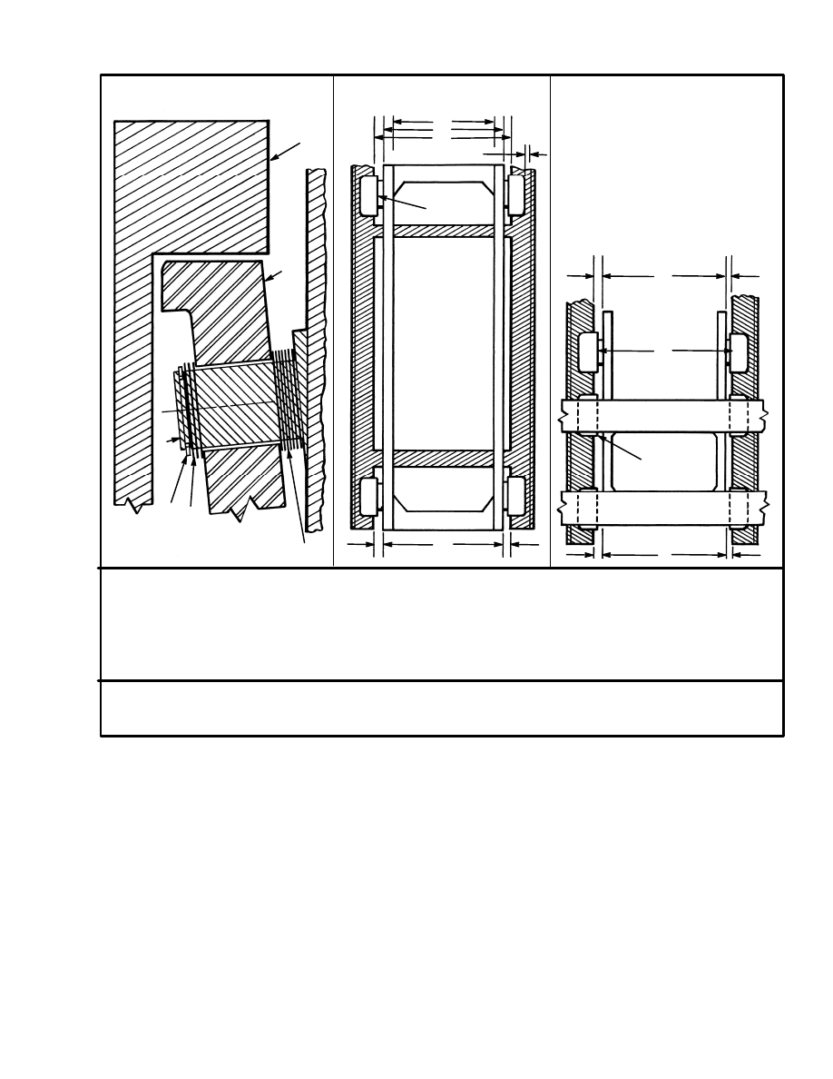
USE SHIMS TO KEEP CARRIAGE AND MAST WELDMENTS PARALLEL, TO GIVE APPROXIMATELY
EQUAL SPACE BETWEEN BOTH SIDES OF CARRIAGE AND WELDMENTS AND TO GIVE THE COR-
RECT CLEARANCE AT POINT OF TIGHTEST FIT.
FIGURE 10. MAST ADJUSTMENTS
4690
1. CHANNEL
2. LOAD ROLLER
3. STUB SHAFT
4. SNAP RING
5. SHIMS
6. PARALLEL
7. 0.1–0.8 mm (0.004–0.030 in)
8. EQUAL SPACE
±
1.5 mm
(0.060 in)
9. PARALLEL
10. PUT SPACER ON OUTSIDE
OF TOP LOAD ROLLER,
UNDER SNAP RING
11. SHIM FOR 0.8 mm (0.030 in)
MAXIMUM CLEARANCE AT
POINT OF TIGHTEST FIT
TOP VIEW
MAST
FRONT VIEW
CARRIAGE
FRONT VIEW
1
2
5
4
5
3
6
7
2
8
8
9
10
11
When the mast is assembled, the same shim arrange-
ment is used as before disassembly. Make notes of each
shim arrangement during disassembly. Check the clear-
ance to adjust for wear or change because of repairs.
1. The load rollers control the alignment of the weld-
ments. The alignment conditions are given on a list be-
low with the most important condition first. See
FIGURE 10.
2. The vertical channels must be parallel to decrease
wear.
3. The maximum clearance between the load roller and
the channel at the tightest fit is 0.8 mm (0.030 in).
4. The arrangement of shims on a stub shaft must be a
similar arrangement of shims on the stub shaft in the op-
posite channel. Each weldment will then be approxi-
mately in the center of the weldment in which it is in-
stalled.
5. Do the following steps to adjust the mast load rollers:
a. Use a crowbar to move the weldments from side
to side to measure the movement. Measure the
14
movement in a minimum of three different posi-
tions of the weldments.
b. Separate the mast weldments and change the
shim arrangements as required. Assemble the
weldments. Slide the weldment all the way to the
top and bottom to find the tightest fit.
c. Repeat Steps 1 and 2 until the clearance is not
more than 0.8 mm (0.030 in) at the tightest fit.
d. Measure the distance on the top and bottom be-
tween the weldments. Change shims to keep the
distance equal between the top and bottom so that
the mast weldments are parallel.
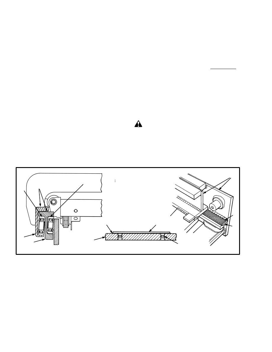
6. Adjust the strip bearings. See FIGURE 11. Insert
shims between the strip bearing and the spacer bar. Ad-
just the clearance until there is less than 0.8 mm (0.030
in) at the tightest fit. See FIGURE 10.
CARRIAGE ADJUSTMENTS
(See FIGURE 10.)
1. Install the six load rollers on the carriage. Install the
shims for the rollers in the same sequence on the stub
shaft before disassembly.
2. Use a lifting device to raise the carriage up the inner
channel. Find the tightest fit between the load rollers and
the inner channels.
3. Remove the carriage from the mast. Adjust the shim
arrangement for each roller for clearance between the
roller and the inner channel. Maximum clearance is 0.8
mm (0.030 in) at the tightest fit. Repeat Steps 2 and 3 if
necessary.
4. Keep the shim arrangement on each side of the car-
riage approximately equal. The carriage must run paral-
lel with the inner mast channel.
5. After adjustment, lubricate the channels with a thin
layer of grease.
CAUTION
Too much grease will cause the rollers to slide and
wear flat areas on the rollers.
6. Adjust the hydraulic hoses and make sure the connec-
tions are correct if the carriage is equipped with hydrau-
lic attachments.
FIGURE 11. ARRANGEMENT OF THE STRIP BEARINGS
10106
2
1.STRIP BEARING
2. LOAD ROLLER
3. WELDMENT
4. SHIMS
5. O–RING
1
3
4
2
3
3
3
4
1
5
3
3
3

15
No movement of lift cylinders
Lift Control linkage is disconnected.
No oil or not enough oil to the lift cylinders.
Slow action of lift cylinders
Not enough oil to lift cylinders.
Bad lift cylinder seals.
Relief valve is set wrong at main control valve.
Rough movement of the upright assembly
Air in the hydraulic system.
Bent cylinder rod or damaged cylinder shell.
The upright assembly is damaged or not in alignment.
The tilt cylinder movement is slow
or is not smooth
There is not enough oil going to the tilt cylinders.
The seals in the tilt cylinders are worn or damaged.
There is air in the hydraulic system.
The tilt cylinders have internal damage.
There is leakage in the hydraulic lines of the tilt system.
The seals in the tilt cylinders are worn or damaged.
The main control valve is worn or damaged.
The tilt cylinders tilt the upright
forward or backward too slowly.
The main control valve has a defect.
There is a leak in the hydraulic system.
PROBLEM
CAUSE
Lift cylinders have internal or external leaks.
Hydraulic leaks, bad pump or pump drive, relief valve
set too low or a bad check valve.
There is a restriction in the lines of the tilt system.
The relief pressure at the main control valve is not correct.
The tilt cylinders permit mast movement
when the control lever is in the NEUTRAL
position.
TROUBLESHOOTING
Document Outline
Wyszukiwarka
Podobne podstrony:
897928 2200SRM0625 (12 1996) UK EN
897506 4000SRM0521 (05 2004) UK EN
1452930 8000SRM0680 (12 2002) UK EN
897856 2200SRM0612 (01 1996) UK EN
1466211 2000SRM0754 (12 2003) UK EN
1494141 1800SRM0937 (12 2003) UK EN
1569718 4000SRM1160 (08 2005) UK EN
1494143 2200SRM0939 (12 2004) UK EN
897988 4000SRM0660 (05 1997) UK EN
1483865 8000SRM0916 (12 2003) UK EN
897209 4000SRM0374 (03 1993) UK EN(1)
897001 8000SRM0291 (12 1993) UK EN
897989 4000SRM0661 (02 2004) UK EN
1466169 4000SRM0741 (03 2005) UK EN
910442 8000SRM0231 (12 2004) UK EN
więcej podobnych podstron