1 (159)
Strona 20 z 46
Spy Circuits
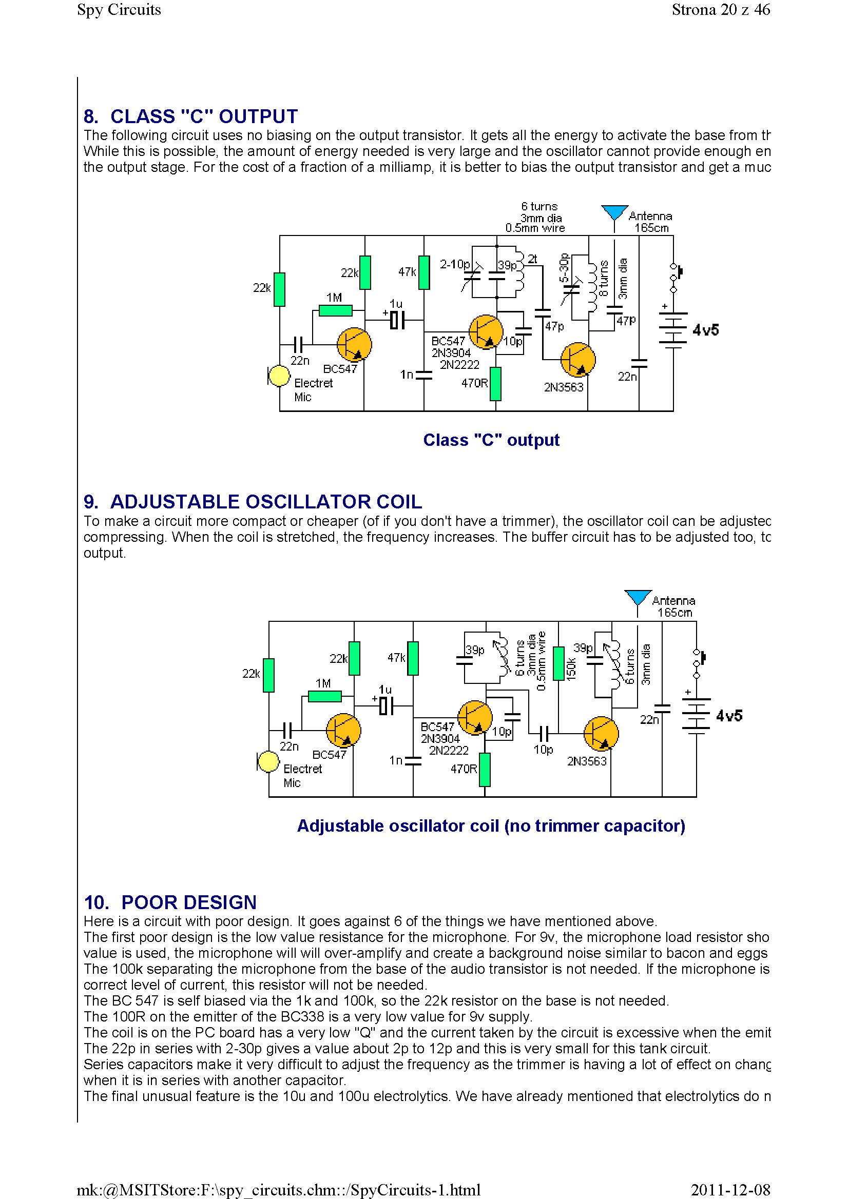
8. CLASS "C" OUTPUT
The following Circuit uses no biasing on the output transistor. It gets all the energy to activate the base from tf While this is possible, the amount of energy needed is very large and the oscillator cannot provide enough en the output stage. For the cost of a fraction of a milliamp, it is better to bias the output transistor and get a muc
6 turns 3mm dia 0.5mm wire
4v5
YArrtenna 165cm
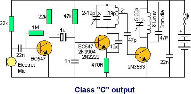
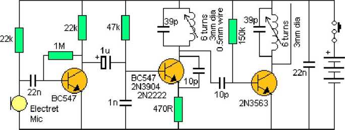
9. ADJUSTABLE OSCILLATOR COIL
To make a Circuit morę compact or cheaper (of if you don't have a trimmer), the oscillator coil can be adjustec compressing. When the coil is stretched, the frequency increases. The buffer Circuit has to be adjusted too, tc output.
\/ Antenna I 165cm
Adjustable oscillator coil (no trimmer capacitor)
10. POOR DESIGN
Here is a Circuit with poor design. It goes against 6 of the things we have mentioned above.
The first poor design is the Iow value resistance for the microphone. For 9v, the microphone load resistor sho value is used, the microphone will will over-amplify and create a background noise similarto bacon and eggs The 100k separating the microphone from the base of the audio transistor is not needed. If the microphone is correct level of current, this resistor will not be needed.
The BC 547 is self biased via the 1 k and 100k, so the 22k resistor on the base is not needed.
The 100R on the emitter of the BC338 is a very Iow value for 9v supply.
The coil is on the PC board has a very Iow "Q" and the current taken by the Circuit is excessive when the emit The 22p in series with 2-30p gives a value about 2p to 12p and this is very smali for this tank Circuit.
Series capacitors make it very difficult to adjust the frequency as the trimmer is having a lot of effect on chanę when it is in series with another capacitor.
The finał unusual feature is the 10u and 100u electrolytics. We have already mentioned that electrolytics do n
2011-12-08
mk:@MSITStore:F:\spy circuits.chm::/SpyCircuits-l.html
Wyszukiwarka
Podobne podstrony:
1 (181) Strona 42 z 46 Spy Circuits coil. Ali the othertransmitters have sufficient output to detect
1 (151) Strona 12 z 46 Spy Circuits - 5v for maximum output. The Voyager has been copied by many kit
1 (161) Strona 22 z 46 Spy Circuits There is no evidence of the above Circuit de!ivering morę output
1 (163) Strona 24 z 46 Spy Circuits This covers all the possible combinations for the greatest outpu
1 (149) Strona 10 z 46 Spy Circuits2 TRANSISTOR CIRCUITS The next progressive step is to add a trans
1 (150) Strona 11 z 46 Spy Circuits magnetic field" and this occurs when the coil collapses and
1 (154) Strona 15 z 46 Spy Circuits To get good audio ampiification, and a stable oscillator and the
1 (157) Strona 18 z 46 Spy Circuits4. DIFFERENT COUPLING We have already mentioned the fact that a c
1 (160) Strona 21 z 46 Spy Circuits with frequencies around 100MHz. It seems the designer had diffic
1 (162) Strona 23 z 46 Spy Circuits When you fix these faults you will see how much improvement you
1 (166) Strona 27 z 46 Spy Circuits corwert a high-voltage at low-current into a low-voltage at high
1 (167) Strona 28 z 46 Spy Circuits But it is often quite inconvenient to use a long antenna, so her
1 (168) Strona 29 z 46 Spy Circuits A Circuit diagram does not show the screening necessary to keep
1 (169) Strona 30 z 46 Spy Circuits You can learn a lot about designing a Circuit by looking at faul
1 (170) Strona 31 z 46 Spy Circuits This means a certain amount of the energy delivered by the 4p7 w
1 (172) Strona 33 z 46 Spy Circuits AER I AL 1. You don t need 10u and 100u electr
1 (173) Strona 34 z 46 Spy CircuitsTELEPHONE BUG Look at the coil. A floppy coil like this is totall
1 (176) Strona 37 z 46 Spy Circuits junction of the DC amplifier transistor only allowing ,6v to app
1 (178) Strona 39 z 46 Spy Circuits We needrYt say any morę about construction as you will obvious!y
więcej podobnych podstron