1 (181)
Strona 42 z 46
Spy Circuits
coil.
Ali the othertransmitters have sufficient output to detect the radiation when the antenna is outstretched.
With some of the transmitters, the tank Circuit must be adjusted so that the output is a maximum. if you have a radio with a signai strength meter, you won't need this project, but if you don't, it's what you nee Most Field Strength Meters are designed for connection to transmitters with an output of 1 to 1000 watts and detecting outputs in the milliwatt rangę.
For Iow outputs we need a Field Strength Meter that will detect 1 - 50 milliwatts and that's why we designed t\ As we have said, it is an adaptation of Field Strength Meter Mkl and in place of the meter in the output we has 3 LEDs. This makes it self-contained and "frees-up" your multimeter for other uses.
The third feature mentioned in the introduction enables you to determine the frequency of detuned transmittei detect frequencies as Iow as 75MHz.
This is very handy when designing transmitters for operation below the 88MHz band.
When working with a transmitter in this rangę it is important to keep the frequency just below 88MHz as man> detuned a few MHz before the stations at the top of the dial start to appear at the bottom.
If a bug is below this limit it will be impossible to find, even on a detuned radio.
There are two methods of detuning a radio.
One is to move the turns of the air coil near the tuning gang and see if the stations move up or down the dial. To produce a space at the bottom of the band, the stations must be moved up and if you squash the turns toc stations will wrap around and appear at the bottom.
The other method is to adjust the trimmers on the back of the tuning gang. This has proven to be the easiest. Simply tum the trimmers until a space is created at the bottom of the dial and your transmitter can be fitted inl created.
When you try to pick up the transmitter on a normal radio, it will be invisible!

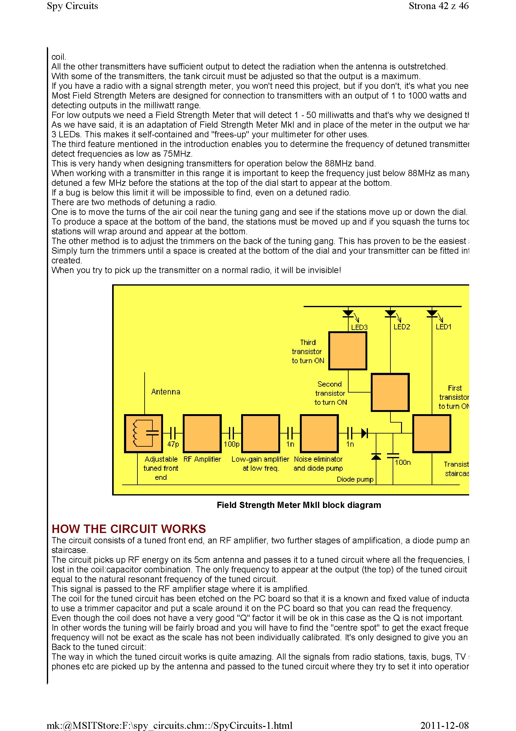
Field Strength Meter Mkll błock diagram
HOW THE CIRCUIT WORKS
The Circuit consists of a tuned front end, an RF amplifier, two further stages of amplification, a diodę pump an staircase.
The Circuit picks up RF energy on its 5cm antenna and passes it to a tuned Circuit where all the frequencies, I lost in the coil:capacitor combination. The only frequency to appear at the output (the top) of the tuned Circuit equai to the natural resonant frequency of the tuned Circuit.
This signai is passed to the RF amplifier stage where it is amplified.
The coil for the tuned Circuit has been etched on the PC board so that it is a known and fixed value of inducta to use a trimmer capacitor and put a scalę around it on the PC board so that you can read the frequency. Even though the coil does not have a very good "Q" factor it will be ok in this case as the Q is not important.
In other words the tuning wili be fairly broad and you will have to find the "centre spot" to get the exact freque frequency will not be exact as the scalę has not been individually calibrated. It's only designed to give you an Back to the tuned Circuit:
The way in which the tuned Circuit works is quite amazing. All the signals from radio stations, taxis, bugs, TV : phones etc are picked up by the antenna and passed to the tuned Circuit where they try to set it into operatior
2011-12-08
mk:@MSITStore:F:\spy circuits.chm::/SpyCircuits-l.html
Wyszukiwarka
Podobne podstrony:
1 (176) Strona 37 z 46 Spy Circuits junction of the DC amplifier transistor only allowing ,6v to app
1 (182) Strona 43 z 46 Spy Circuits lt s a bit like hundreds of people trying to push a person on a
1 (150) Strona 11 z 46 Spy Circuits magnetic field" and this occurs when the coil collapses and
1 (173) Strona 34 z 46 Spy CircuitsTELEPHONE BUG Look at the coil. A floppy coil like this is totall
1 (149) Strona 10 z 46 Spy Circuits2 TRANSISTOR CIRCUITS The next progressive step is to add a trans
1 (151) Strona 12 z 46 Spy Circuits - 5v for maximum output. The Voyager has been copied by many kit
1 (154) Strona 15 z 46 Spy Circuits To get good audio ampiification, and a stable oscillator and the
1 (157) Strona 18 z 46 Spy Circuits4. DIFFERENT COUPLING We have already mentioned the fact that a c
1 (159) Strona 20 z 46 Spy Circuits8. CLASS "C" OUTPUT The following Circuit uses no biasi
1 (160) Strona 21 z 46 Spy Circuits with frequencies around 100MHz. It seems the designer had diffic
1 (161) Strona 22 z 46 Spy Circuits There is no evidence of the above Circuit de!ivering morę output
1 (162) Strona 23 z 46 Spy Circuits When you fix these faults you will see how much improvement you
1 (163) Strona 24 z 46 Spy Circuits This covers all the possible combinations for the greatest outpu
1 (166) Strona 27 z 46 Spy Circuits corwert a high-voltage at low-current into a low-voltage at high
1 (167) Strona 28 z 46 Spy Circuits But it is often quite inconvenient to use a long antenna, so her
1 (168) Strona 29 z 46 Spy Circuits A Circuit diagram does not show the screening necessary to keep
1 (169) Strona 30 z 46 Spy Circuits You can learn a lot about designing a Circuit by looking at faul
1 (170) Strona 31 z 46 Spy Circuits This means a certain amount of the energy delivered by the 4p7 w
1 (172) Strona 33 z 46 Spy Circuits AER I AL 1. You don t need 10u and 100u electr
więcej podobnych podstron