1 (172)

Strona 33 z 46
Spy Circuits
AER I AL
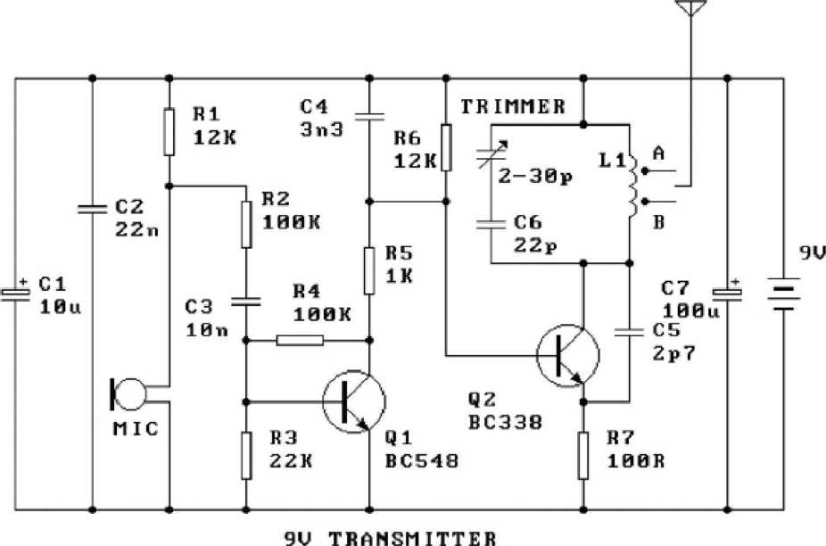
1. You don't need 10u and 100u electrolytics. You don't need any electrolytics AT ALL.
2. The microphone is heavily turned on via the 12k resistor then its output is attenuated by the 100k resistor. 1 and will overload the microphone considerably.
3. The oscillator is DC biased via the first transistor and this is not a good arrangement. The oscillator should biased."
4. The trimmer capacitor should be in parallel with the 22p so that it has a smali effect on adjusting the frequei
5. R5 will have almost no effect on the operation of the Circuit and is not needed.
6. BC338 is a power transistor and is not designed for 100MHz operation.
7. The 22n should be across the battery (and not atthe audio end of the Circuit) because the function of the the power rails "tight" at the oscillator end.
8. The coil is etched on the PC board and this type of coil has a very Iow "Q." The Circuit will have a very Iow c Overall the Circuit is a very poor design and is not worth building.
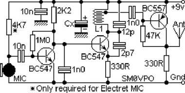
A number of major faults with this Circuit.
1. The 4k7 feeding the electret microphone istoo Iow. It should be 47kto prevent overloading the microphone
2. The coil on the PC board has a very Iow "Q" and will produce a very Iow output.
3. The 12p across the coil istoo Iow. It should be 33p to 47p and the coil should be changed to 6 turns 3mm d wire so the two components have the correct L-C ratio.
4. There is no way to adjust the frequency of transmission.
5. The coupling capacitor to the finał transistor istoo high. It should be 47p maximum.
6. A BC557 transistor is not a good RF amplifier.
2011-12-08
mk:@MSITStore:F:\spy circuits.chm::/SpyCircuits-l.html
Wyszukiwarka
Podobne podstrony:
1 (181) Strona 42 z 46 Spy Circuits coil. Ali the othertransmitters have sufficient output to detect
1 (142) Strona 3 z 46 Spy Circuits pulse is amplified by the transistor and the Circuit is kept acti
1 (149) Strona 10 z 46 Spy Circuits2 TRANSISTOR CIRCUITS The next progressive step is to add a trans
1 (150) Strona 11 z 46 Spy Circuits magnetic field" and this occurs when the coil collapses and
1 (151) Strona 12 z 46 Spy Circuits - 5v for maximum output. The Voyager has been copied by many kit
1 (154) Strona 15 z 46 Spy Circuits To get good audio ampiification, and a stable oscillator and the
1 (157) Strona 18 z 46 Spy Circuits4. DIFFERENT COUPLING We have already mentioned the fact that a c
1 (159) Strona 20 z 46 Spy Circuits8. CLASS "C" OUTPUT The following Circuit uses no biasi
1 (160) Strona 21 z 46 Spy Circuits with frequencies around 100MHz. It seems the designer had diffic
1 (161) Strona 22 z 46 Spy Circuits There is no evidence of the above Circuit de!ivering morę output
1 (162) Strona 23 z 46 Spy Circuits When you fix these faults you will see how much improvement you
1 (163) Strona 24 z 46 Spy Circuits This covers all the possible combinations for the greatest outpu
1 (166) Strona 27 z 46 Spy Circuits corwert a high-voltage at low-current into a low-voltage at high
1 (167) Strona 28 z 46 Spy Circuits But it is often quite inconvenient to use a long antenna, so her
1 (168) Strona 29 z 46 Spy Circuits A Circuit diagram does not show the screening necessary to keep
1 (169) Strona 30 z 46 Spy Circuits You can learn a lot about designing a Circuit by looking at faul
1 (170) Strona 31 z 46 Spy Circuits This means a certain amount of the energy delivered by the 4p7 w
1 (173) Strona 34 z 46 Spy CircuitsTELEPHONE BUG Look at the coil. A floppy coil like this is totall
1 (176) Strona 37 z 46 Spy Circuits junction of the DC amplifier transistor only allowing ,6v to app
więcej podobnych podstron