1 (163)
Strona 24 z 46
Spy Circuits
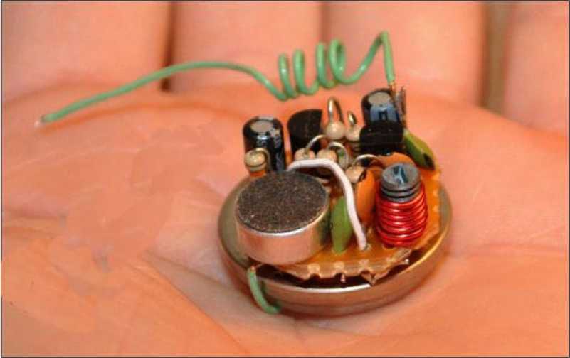
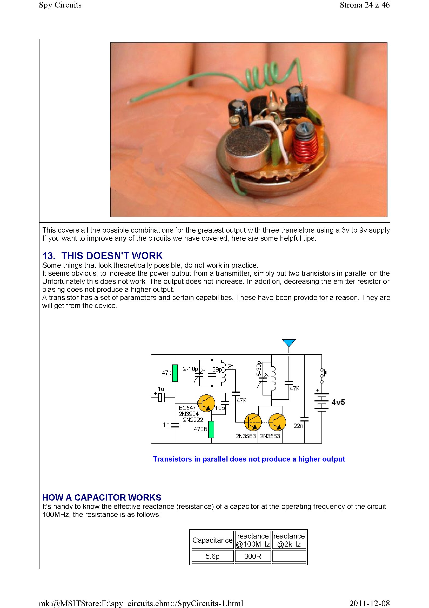
This covers all the possible combinations for the greatest output with three transistors using a 3v to 9v supply If you want to improve any of the circuits we have covered, here are some helpfui tips:
13. THIS DOESNT WORK
Some things that iooktheoreticaiiy possible, do not work in practice.
It seems obvious, to increase the power output from a transmitter, simply put two transistors in parał lei on the Unfortunately this does not work. The output does not increase. In addition, decreasing the emitter resistor or biasing does not produce a higher output.
A transistor has a set of parameters and certain capabilities. These have been provide for a reason. They are will get from the device.
Y
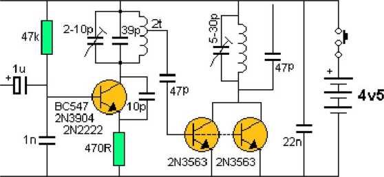
Transistors in parailel does not produce a higher output
HOW A CAPACITOR WORKS
lt's handy to know the effective reactance (resistance) of a capacitor at the operating frequency of the Circuit. 100MHz, the resistance is as follows:
|
Capacitance |
reactance @100MHz |
reactance @2kHz |
|
5.6p |
300R |
2011-12-08
mk:@MSITStore:F:\spy circuits.chm::/SpyCircuits-l.html
Wyszukiwarka
Podobne podstrony:
1 (170) Strona 31 z 46 Spy Circuits This means a certain amount of the energy delivered by the 4p7 w
1 (173) Strona 34 z 46 Spy CircuitsTELEPHONE BUG Look at the coil. A floppy coil like this is totall
1 (180) Strona 41 z 46 Spy Circuits This project has 3 features. 1. It s a Field S
1 (150) Strona 11 z 46 Spy Circuits magnetic field" and this occurs when the coil collapses and
1 (181) Strona 42 z 46 Spy Circuits coil. Ali the othertransmitters have sufficient output to detect
1 (149) Strona 10 z 46 Spy Circuits2 TRANSISTOR CIRCUITS The next progressive step is to add a trans
1 (151) Strona 12 z 46 Spy Circuits - 5v for maximum output. The Voyager has been copied by many kit
1 (154) Strona 15 z 46 Spy Circuits To get good audio ampiification, and a stable oscillator and the
1 (157) Strona 18 z 46 Spy Circuits4. DIFFERENT COUPLING We have already mentioned the fact that a c
1 (159) Strona 20 z 46 Spy Circuits8. CLASS "C" OUTPUT The following Circuit uses no biasi
1 (160) Strona 21 z 46 Spy Circuits with frequencies around 100MHz. It seems the designer had diffic
1 (161) Strona 22 z 46 Spy Circuits There is no evidence of the above Circuit de!ivering morę output
1 (162) Strona 23 z 46 Spy Circuits When you fix these faults you will see how much improvement you
1 (166) Strona 27 z 46 Spy Circuits corwert a high-voltage at low-current into a low-voltage at high
1 (167) Strona 28 z 46 Spy Circuits But it is often quite inconvenient to use a long antenna, so her
1 (168) Strona 29 z 46 Spy Circuits A Circuit diagram does not show the screening necessary to keep
1 (169) Strona 30 z 46 Spy Circuits You can learn a lot about designing a Circuit by looking at faul
1 (172) Strona 33 z 46 Spy Circuits AER I AL 1. You don t need 10u and 100u electr
1 (176) Strona 37 z 46 Spy Circuits junction of the DC amplifier transistor only allowing ,6v to app
więcej podobnych podstron