1 (180)
Strona 41 z 46
Spy Circuits
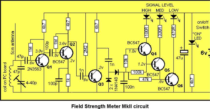
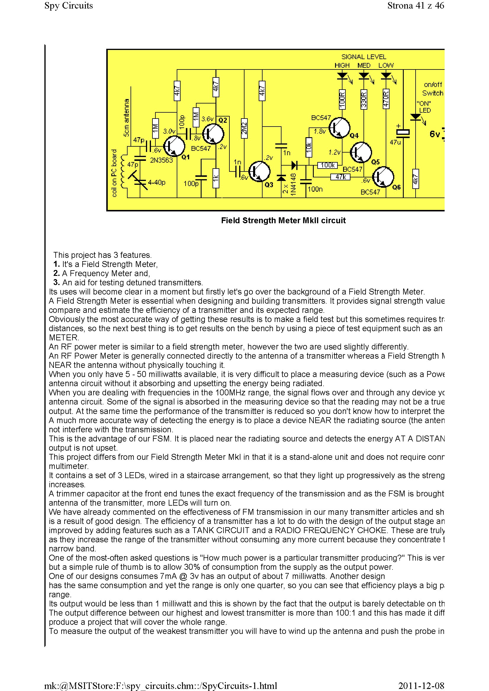
This project has 3 features.
1. It's a Field Strength Meter,
2. A Frequency Meter and,
3. An aid for testing detuned transmitters.
Its uses will become elear in a moment but firstly let's go over the background of a Field Strength Meter.
A Field Strength Meter is essential when designing and building transmitters. It provides signal strength value comparę and estimate the efficiency of a transmitter and its expected rangę.
Obviously the most accurate way of getting these results is to make a field test but this sometimes requires tr distances, so the next best thing is to get results on the bench by using a piece of test equipment such as an METER.
An RF power meter is similar to a field strength meter, however the two are used slightly differently.
An RF Power Meter is generał ly connected directly to the anten na of a transmitter whereas a Field Strength h NEAR the antenna without physically touching it.
When you only have 5 - 50 milliwatts available, it is very difficult to place a measuring device (such as a Powe antenna Circuit without it absorbing and upsetting the energy being radiated.
When you are dealing with frequencies in the 100MHz rangę, the signal flows over and through any device yc antenna Circuit. Some of the signal is absorbed in the measuring device so that the reading may not be a true output. At the same time the performance of the transmitter is reduced so you don't know how to interpret the A much morę accurate way of detecting the energy is to place a device NEAR the radiating source (the anten not interfere with the transmission.
This is the advantage of our FSM. It is placed near the radiating source and detects the energy AT A DISTAN output is not upset.
This project differs from our Field Strength Meter Mkl in that it is a stand-alone unit and does not require conr multimeter.
It contains a set of 3 LEDs, wired in a staircase arrangement, so that they light up progressively as the streng inereases.
A trimmer capacitor at the front end tunes the exact frequency of the transmission and as the FSM is brought antenna of the transmitter, morę LEDs will turn on.
We have already commented on the effectiveness of FM transmission in our many transmitter articles and sh is a result of good design. The efficiency of a transmitter has a lot to do with the design of the output stage an improved by adding features such as a TANK CIRCUIT and a RADIO FREOUENCY CHOKE. These are truły as they inerease the rangę of the transmitter without consuming any morę current because they concentrate t narrow band.
One of the most-often asked questions is "How much power is a particular transmitter producing?" This is ver but a simple rule of thumb is to allow 30% of consumption from the supply as the output power.
One of our designs consumes 7mA @ 3v has an output of about 7 milliwatts. Another design
has the same consumption and yet the rangę is only one quarter, so you can see that efficiency plays a big p;
rangę.
Its output would be less than 1 milliwatt and this is shown by the fact that the output is barely detectable on th The output difference between our highest and lowest transmitter is morę than 100:1 and this has madę it diff produce a project that wili cover the whole rangę.
To measure the output of the weakest transmitter you wili have to wind up the antenna and push the probe in
2011-12-08
mk:@MSITStore:F:\spy circuits.chm::/SpyCircuits-l.html
Wyszukiwarka
Podobne podstrony:
1 (163) Strona 24 z 46 Spy Circuits This covers all the possible combinations for the greatest outpu
1 (170) Strona 31 z 46 Spy Circuits This means a certain amount of the energy delivered by the 4p7 w
1 (160) Strona 21 z 46 Spy Circuits with frequencies around 100MHz. It seems the designer had diffic
1 (150) Strona 11 z 46 Spy Circuits magnetic field" and this occurs when the coil collapses and
1 (173) Strona 34 z 46 Spy CircuitsTELEPHONE BUG Look at the coil. A floppy coil like this is totall
1 (179) Strona 40 z 46 Spy CircuitsEXPERIMENTING Take the Voyager project and connect 30cm of tinned
1 (181) Strona 42 z 46 Spy Circuits coil. Ali the othertransmitters have sufficient output to detect
1 (149) Strona 10 z 46 Spy Circuits2 TRANSISTOR CIRCUITS The next progressive step is to add a trans
1 (151) Strona 12 z 46 Spy Circuits - 5v for maximum output. The Voyager has been copied by many kit
1 (154) Strona 15 z 46 Spy Circuits To get good audio ampiification, and a stable oscillator and the
1 (157) Strona 18 z 46 Spy Circuits4. DIFFERENT COUPLING We have already mentioned the fact that a c
1 (159) Strona 20 z 46 Spy Circuits8. CLASS "C" OUTPUT The following Circuit uses no biasi
1 (161) Strona 22 z 46 Spy Circuits There is no evidence of the above Circuit de!ivering morę output
1 (162) Strona 23 z 46 Spy Circuits When you fix these faults you will see how much improvement you
1 (166) Strona 27 z 46 Spy Circuits corwert a high-voltage at low-current into a low-voltage at high
1 (167) Strona 28 z 46 Spy Circuits But it is often quite inconvenient to use a long antenna, so her
1 (168) Strona 29 z 46 Spy Circuits A Circuit diagram does not show the screening necessary to keep
1 (169) Strona 30 z 46 Spy Circuits You can learn a lot about designing a Circuit by looking at faul
1 (172) Strona 33 z 46 Spy Circuits AER I AL 1. You don t need 10u and 100u electr
więcej podobnych podstron