1 (179)
Strona 40 z 46
Spy Circuits
EXPERIMENTING
Take the Voyager project and connect 30cm of tinned copper wire to the antenna point on the PC board. Holc Meter in your hand (keep away from the actual Circuit by holding the multimeter) and bring the receiving anter Voyager antenna, without touching it. As you move up and down the Voyager antenna, watch the needle. it will show that energy is not radiated uniformly from the antenna but has a maximum and minimum value. It where these occur. Measure the length of the antenna and plot the results. Cut 2cm off the antenna and repe 175cm antenna to the bug and repeat the tests.
This will give you a good understanding of the phenomenon of electromagnetic radiation.
There are lots of other things you can test with this project.
The Field Strength Meter Mkll is presented in the next article and has the advantage of a tuned front end and This will enable you to not only peak transmitters but also find the frequency on which they are operating.
It detects in the rangę 75MHz to 140MHz enabling you to design and build transmitters capable of transmittin: broadcast band.
But don't put off building this project as you will need both of them as they have different capabilities. And yoi Power Meter.
Test eguipment is very important when working with RF so don't put it off any longer, start now and build up y
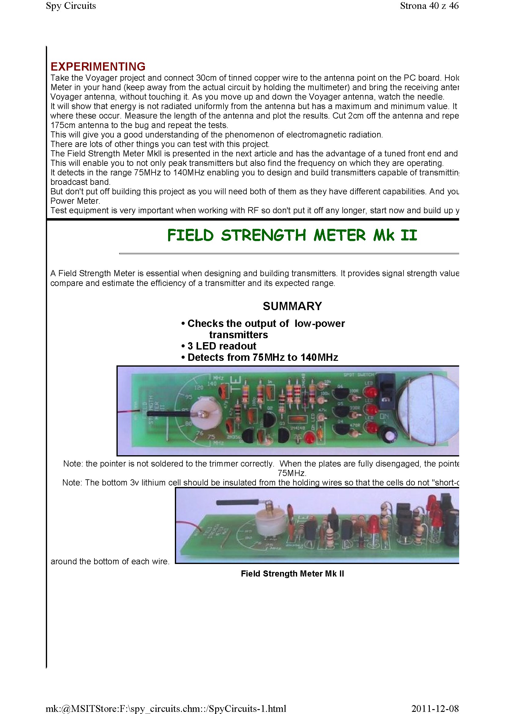
FIELD STRENGTH METER Mk II
A Field Strength Meter is essential when designing and building transmitters. It provides signal strength value compare and estimate the efficiency of a transmitter and its expected rangę.
SUMMARY
• Checks the output of low-power
transmitters
• 3 LED readout
• Detects from 75MHz to 140MHz
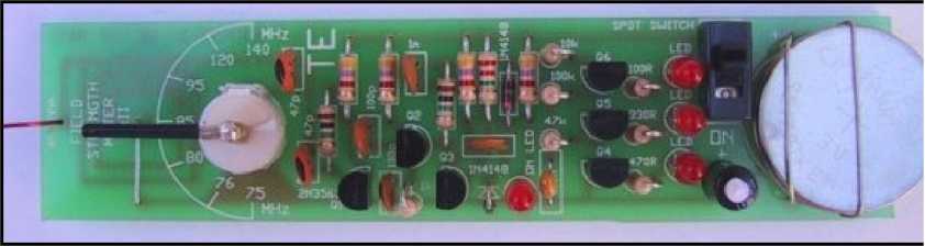
Notę: the pointer is not soldered to the trimmer correctiy. When the plates are fully disengaged, the pointę
75MHz.
Notę: The bottom 3v lithium celi should be insulated from the holding wires so that the cells do not "short-c
around the bottom of each wire.
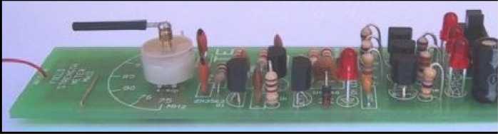
Field Strength Meter Mk II
2011-12-08
mk:@MSITStore:F:\spy circuits.chm::/SpyCircuits-l.html
Wyszukiwarka
Podobne podstrony:
1 (181) Strona 42 z 46 Spy Circuits coil. Ali the othertransmitters have sufficient output to detect
1 (149) Strona 10 z 46 Spy Circuits2 TRANSISTOR CIRCUITS The next progressive step is to add a trans
1 (150) Strona 11 z 46 Spy Circuits magnetic field" and this occurs when the coil collapses and
1 (151) Strona 12 z 46 Spy Circuits - 5v for maximum output. The Voyager has been copied by many kit
1 (154) Strona 15 z 46 Spy Circuits To get good audio ampiification, and a stable oscillator and the
1 (157) Strona 18 z 46 Spy Circuits4. DIFFERENT COUPLING We have already mentioned the fact that a c
1 (159) Strona 20 z 46 Spy Circuits8. CLASS "C" OUTPUT The following Circuit uses no biasi
1 (160) Strona 21 z 46 Spy Circuits with frequencies around 100MHz. It seems the designer had diffic
1 (161) Strona 22 z 46 Spy Circuits There is no evidence of the above Circuit de!ivering morę output
1 (163) Strona 24 z 46 Spy Circuits This covers all the possible combinations for the greatest outpu
1 (168) Strona 29 z 46 Spy Circuits A Circuit diagram does not show the screening necessary to keep
1 (170) Strona 31 z 46 Spy Circuits This means a certain amount of the energy delivered by the 4p7 w
1 (173) Strona 34 z 46 Spy CircuitsTELEPHONE BUG Look at the coil. A floppy coil like this is totall
1 (176) Strona 37 z 46 Spy Circuits junction of the DC amplifier transistor only allowing ,6v to app
1 (162) Strona 23 z 46 Spy Circuits When you fix these faults you will see how much improvement you
1 (166) Strona 27 z 46 Spy Circuits corwert a high-voltage at low-current into a low-voltage at high
1 (167) Strona 28 z 46 Spy Circuits But it is often quite inconvenient to use a long antenna, so her
1 (169) Strona 30 z 46 Spy Circuits You can learn a lot about designing a Circuit by looking at faul
1 (172) Strona 33 z 46 Spy Circuits AER I AL 1. You don t need 10u and 100u electr
więcej podobnych podstron