1 (168)
Strona 29 z 46
Spy Circuits
A Circuit diagram does not show the screening necessary to keep the harmonics to a very iow level. You nee the unit and how the components have been laid out.
The construction and placement of the fiitering components on the output is also important.
That's why these circuits are morę complex than just putting the components together and connecting a supp
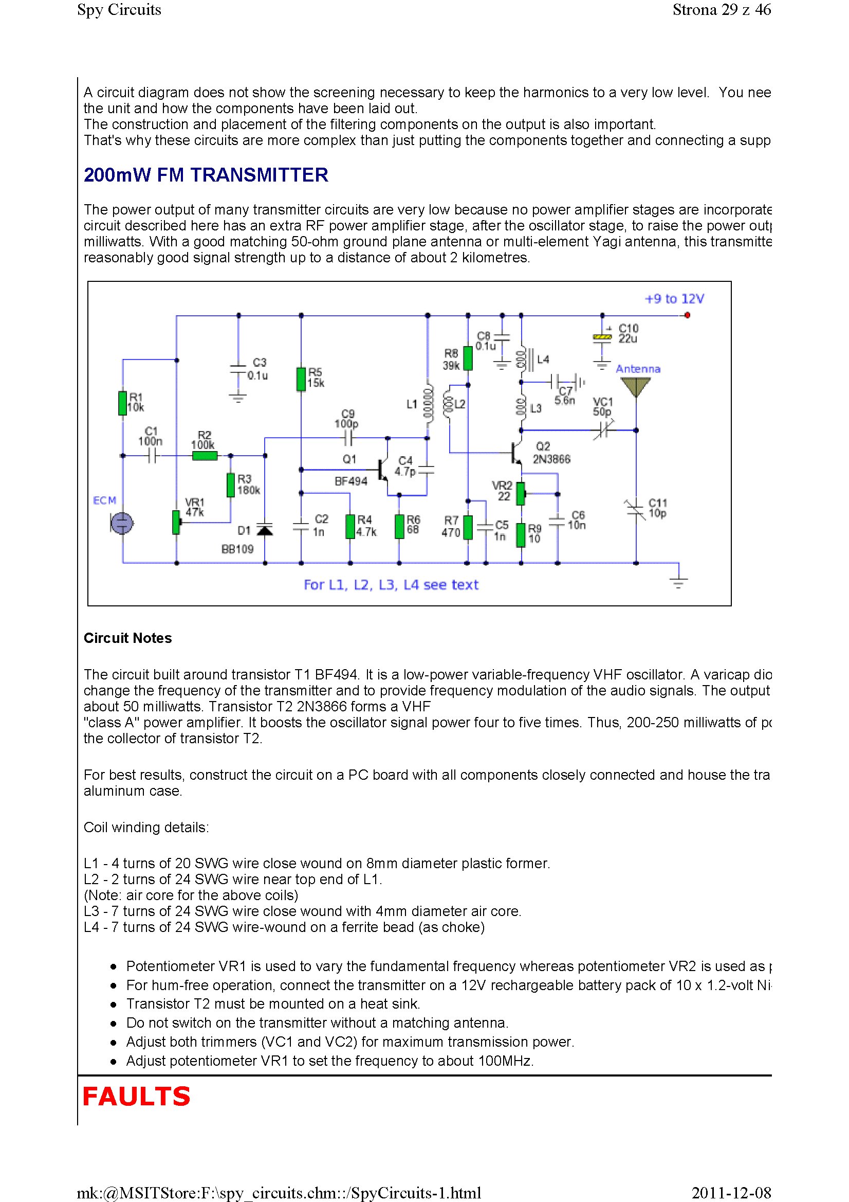
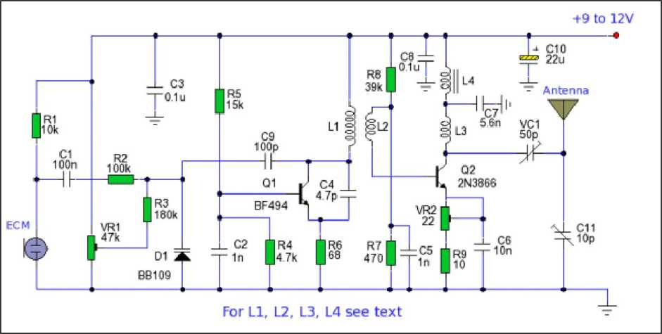
200mW FM TRANSMITTER
The power output of many transmitter circuits are very Iow because no power amplifier stages are incorporate Circuit described here has an extra RF power amplifier stage, afterthe oscillator stage, to raise the power out| milliwatts. With a good matching 50-ohm ground piane antenna or multi-element Yagi antenna, thistransmitte reasonably good signal strength up to a distance of about 2 kilometres.
Circuit Notes
The Circuit built around transistor T1 BF494. It is a low-power variable-frequency VHF oscillator. A varicap dio change the frequency of the transmitter and to provide frequency modulation of the audio signals. The output about 50 milliwatts. Transistor T2 2N3866 forms a VHF
"class A" power amplifier. It boosts the oscillator signal power four to five times. Thus, 200-250 milliwatts of pc the collector of transistor T2.
For best results, construct the Circuit on a PC board with all components closely connected and house the tra aluminum case.
Coil winding details:
L1 - 4 turns of 20 SWG wire close wound on 8mm diameter plastic former.
L2 - 2 turns of 24 SWG wire near top end of L1.
(Notę: air core for the above coils)
L3 - 7 turns of 24 SWG wire close wound with 4mm diameter air core.
L4 - 7 turns of 24 SWG wire-wound on a ferrite bead (as choke)
• Potentiometer VR1 is used to vary the fundamental frequency whereas potentiometer VR2 is used as \
• For hum-free operation, connect the transmitter on a 12V rechargeable battery pack of 10 x 1.2-volt Ni
• Transistor T2 must be mounted on a heat sink.
• Do not switch on the transmitter without a matching antenna.
• Adjust both trimmers (VC1 and VC2) for maximum transmission power.
• Adjust potentiometer VR1 to set the frequency to about 100MHz.
FAULTS
2011-12-08
mk:@MSITStore:F:\spy circuits.chm::/SpyCircuits-l.html
Wyszukiwarka
Podobne podstrony:
1 (151) Strona 12 z 46 Spy Circuits - 5v for maximum output. The Voyager has been copied by many kit
1 (182) Strona 43 z 46 Spy Circuits lt s a bit like hundreds of people trying to push a person on a
1 (181) Strona 42 z 46 Spy Circuits coil. Ali the othertransmitters have sufficient output to detect
1 (142) Strona 3 z 46 Spy Circuits pulse is amplified by the transistor and the Circuit is kept acti
1 (149) Strona 10 z 46 Spy Circuits2 TRANSISTOR CIRCUITS The next progressive step is to add a trans
1 (150) Strona 11 z 46 Spy Circuits magnetic field" and this occurs when the coil collapses and
1 (154) Strona 15 z 46 Spy Circuits To get good audio ampiification, and a stable oscillator and the
1 (157) Strona 18 z 46 Spy Circuits4. DIFFERENT COUPLING We have already mentioned the fact that a c
1 (159) Strona 20 z 46 Spy Circuits8. CLASS "C" OUTPUT The following Circuit uses no biasi
1 (160) Strona 21 z 46 Spy Circuits with frequencies around 100MHz. It seems the designer had diffic
1 (161) Strona 22 z 46 Spy Circuits There is no evidence of the above Circuit de!ivering morę output
1 (162) Strona 23 z 46 Spy Circuits When you fix these faults you will see how much improvement you
1 (163) Strona 24 z 46 Spy Circuits This covers all the possible combinations for the greatest outpu
1 (166) Strona 27 z 46 Spy Circuits corwert a high-voltage at low-current into a low-voltage at high
1 (167) Strona 28 z 46 Spy Circuits But it is often quite inconvenient to use a long antenna, so her
1 (169) Strona 30 z 46 Spy Circuits You can learn a lot about designing a Circuit by looking at faul
1 (170) Strona 31 z 46 Spy Circuits This means a certain amount of the energy delivered by the 4p7 w
1 (172) Strona 33 z 46 Spy Circuits AER I AL 1. You don t need 10u and 100u electr
1 (173) Strona 34 z 46 Spy CircuitsTELEPHONE BUG Look at the coil. A floppy coil like this is totall
więcej podobnych podstron