1 (167)
Strona 28 z 46
Spy Circuits
But it is often quite inconvenient to use a long antenna, so here are some alternatives.
Obviously you can use a shorter antenna, but as you reduce the length, the rangę reduces.
Surprisingly, it does not decrease greatiy when the antenna is reduced to "half-wave" and this is what we hav' Taking Electronics FM transmitters.
Many of the kits on the web are supplied with an antenna 30cm long to reduce the rangę and make the transr legał. But this is not what building and testing is all about.
The hobbyist wants to know how far he can reach with the transmitter he has madę.
Placing the antenna on top of a cupboard is a good choice. It provides height and you can stretch the antennć length.
The receiving antenna on a radio must also be horizontal and somewhere at the front or back of the transmitti If you require omni directional radiation, (radiation 360°) the antenna must be upright (vertical). The receiving be vertica! and can be anywhere in the 360° radius.
We are not going into the complexities of different radiating patterns of antennas but here is one suggestion fc antenna. It is called a DIPOLE. You can get a closed dipole, folded dipole and others but ours is a simple des
THE DIPOLE
If you want to transmit in a particular direction, you can fit a dipole antenna.
This is simply connecting one wire to the antenna output and another wire to the 0v raił and stretching each o opposite directions.
These are called RADIATORS and if you want to have them higher than the transmitter, the two wires run pai and very close. These are called FEEDERS.
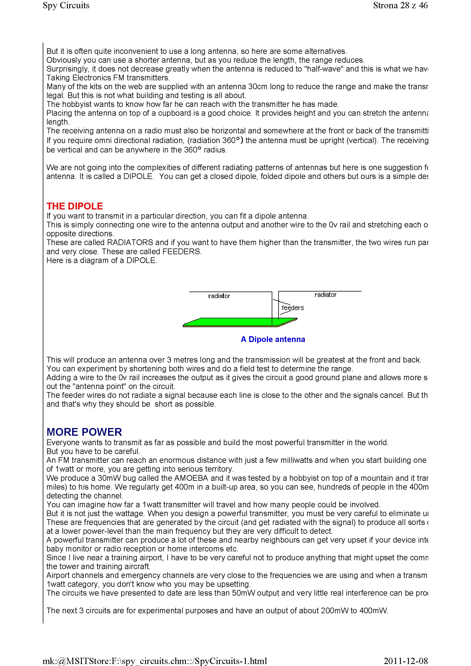
Here is a diagram of a DIPOLE.
|
radiator |
radiator | |
|
feeders | ||
|
W* |
A Dipole antenna
This will produce an antenna over 3 metres long and the transmission will be greatest at the front and back. You can experiment by shortening both wires and do a field test to determine the rangę.
Adding a wire to the 0v raił increases the output as it gives the Circuit a good ground piane and allows morę s out the "antenna point" on the Circuit.
The feeder wires do not radiate a signal because each linę is close to the other and the signals cancel. But th and that's why they should be short as possible.
MORĘ POWER
Everyone wants to transmit as far as possible and build the most powerful transmitter in the worid.
But you have to be careful.
An FM transmitter can reach an enormous distance with just a few milliwatts and when you start building one of 1watt or morę, you are getting into serious territory.
We produce a 30mW bug called the AMOEBA and it was tested by a hobbyist on top of a mountain and it trar miles) to his home. We regularly get 400m in a built-up area, so you can see, hundreds of people in the 400m detecting the channel.
You can imagine how far a 1watt transmitter will travel and how many people could be involved.
But it is not just the wattage. When you design a powerful transmitter, you must be very careful to eliminate ui These are frequencies that are generated by the Circuit (and get radiated with the signal) to produce all sorts < at a lower power-level than the main frequency but they are very difficult to detect.
A powerful transmitter can produce a lot of these and nearby neighbours can get very upset if your device inte baby monitor or radio reception or home intercoms etc.
Since I live near a training airport, I have to be very careful not to produce anything that might upset the comn the tower and training aircraft.
Airport channels and emergency channels are very close to the frequencies we are using and when a transm 1watt category, you don't know who you may be upsetting.
The circuits we have presented to datę are less than 50mW output and very little real interference can be pro< The next 3 circuits are for experimental purposes and have an output of about 200mW to 400mW.
2011-12-08
mk:@MSITStore:F:\spy circuits.chm::/SpyCircuits-l.html
Wyszukiwarka
Podobne podstrony:
1 (151) Strona 12 z 46 Spy Circuits - 5v for maximum output. The Voyager has been copied by many kit
1 (160) Strona 21 z 46 Spy Circuits with frequencies around 100MHz. It seems the designer had diffic
1 (162) Strona 23 z 46 Spy Circuits When you fix these faults you will see how much improvement you
1 (173) Strona 34 z 46 Spy CircuitsTELEPHONE BUG Look at the coil. A floppy coil like this is totall
1 (180) Strona 41 z 46 Spy Circuits This project has 3 features. 1. It s a Field S
1 (181) Strona 42 z 46 Spy Circuits coil. Ali the othertransmitters have sufficient output to detect
1 (149) Strona 10 z 46 Spy Circuits2 TRANSISTOR CIRCUITS The next progressive step is to add a trans
1 (150) Strona 11 z 46 Spy Circuits magnetic field" and this occurs when the coil collapses and
1 (154) Strona 15 z 46 Spy Circuits To get good audio ampiification, and a stable oscillator and the
1 (157) Strona 18 z 46 Spy Circuits4. DIFFERENT COUPLING We have already mentioned the fact that a c
1 (159) Strona 20 z 46 Spy Circuits8. CLASS "C" OUTPUT The following Circuit uses no biasi
1 (161) Strona 22 z 46 Spy Circuits There is no evidence of the above Circuit de!ivering morę output
1 (163) Strona 24 z 46 Spy Circuits This covers all the possible combinations for the greatest outpu
1 (166) Strona 27 z 46 Spy Circuits corwert a high-voltage at low-current into a low-voltage at high
1 (168) Strona 29 z 46 Spy Circuits A Circuit diagram does not show the screening necessary to keep
1 (169) Strona 30 z 46 Spy Circuits You can learn a lot about designing a Circuit by looking at faul
1 (170) Strona 31 z 46 Spy Circuits This means a certain amount of the energy delivered by the 4p7 w
1 (172) Strona 33 z 46 Spy Circuits AER I AL 1. You don t need 10u and 100u electr
1 (176) Strona 37 z 46 Spy Circuits junction of the DC amplifier transistor only allowing ,6v to app
więcej podobnych podstron