
Short
Short
-
-
circuits in networks with neutral not
circuits in networks with neutral not
effec
effec
t
t
iv
iv
e
e
ly
ly
grounded
grounded

2 / 31
Types
Types
of
of
neutral
neutral
handling
handling
The type of neutral earthing determines the zero sequence impedance and has
a dominating influence on the short-circuit current through earth.
The different types of neutral handling in power systems are as follows:
Low-impedance earthing –
grounded / earthed network
3-phase network having its neutral connected with the earth through resistance or
reactance of sufficiently low value, which assures appropriate network operating
conditions during ground short-circuits.
This type of earth connection refers to HV networks.
Isolated neutral –
isolated network
It is a network having no connection with the earth with the exception of such a
connection through high impedance of protection, measurement or signalling
devices.
Isolated networks are LV (690 V) or MV networks of small values of single-phase
short-circuits.

3 / 31
Types
Types
of
of
neutral
neutral
handling
handling
Resonance earthing – compensated network
It is 3-phase network having its neutral connected with the earth through
reactance, value of which is selected to compensate single-phase short-circuit
current. The compensation means spontaneous extinguishing short-circuit arc.
Compensated networks – MV networks of high values of single-phase short-circuit
curents.
Earthing with current limitation – resistor earthed neutral
It is 3-phase MV network having its neutral connected with the earth through
resistance which assures appropriate network operation conditions during earth
short-circuits.
Directly earthed neutral – T type LV network
3-phase or single-phase network with direct neutral connection with the earth.
4 / 31
Short
Short
-
-
circuit in isolated network
circuit in isolated network
E
R
E
S
E
T
R
S
T
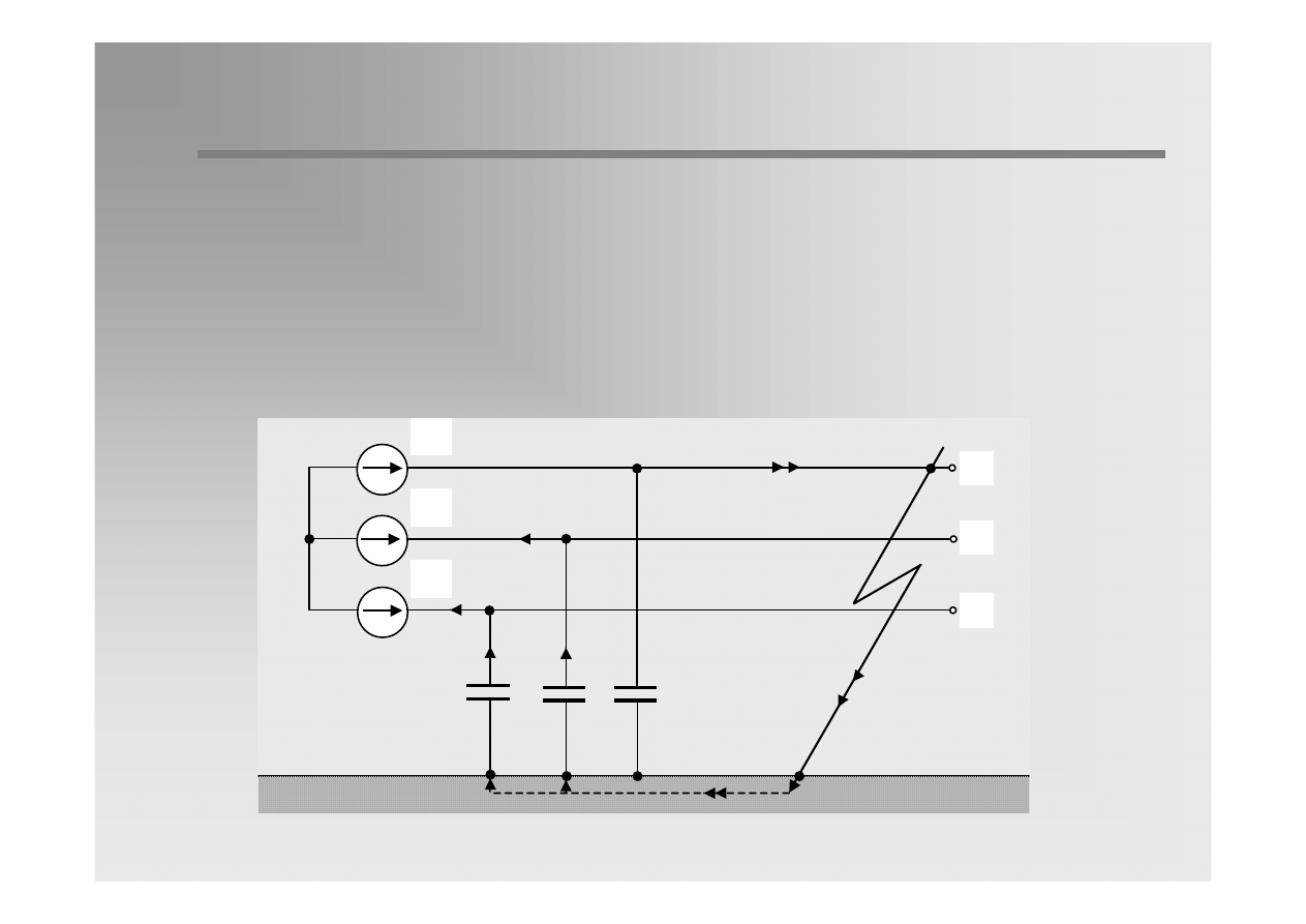
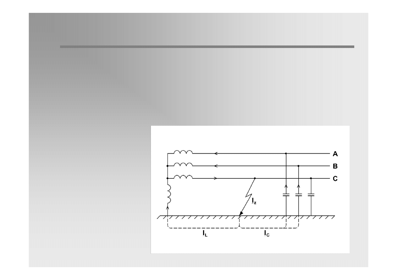
In isolated network the current of single-phase short-circuit flows in the
circuits constituted by the network phase-to-earth capacitances. Its value
is small, because network capacitance present high impedances for the
current flow.
The earth-fault current has capacitive character.
5 / 31
Short
Short
-
-
circuit in isolated network
circuit in isolated network
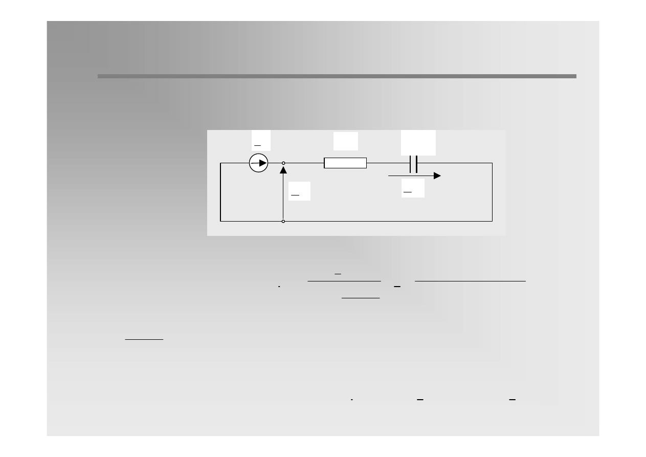
Equivalent circuit diagram
of a single-phase short-
circuit in isolated network.
( )
1
I
( )
1
E
( )
x
1
Z
( )
1
U
( )
x
2
Z
( )
2
U
P
(1)
K
(1)
K
(2)
( )
x
0
Z
( )
0
U
K
(0)
( )
X
1
I
( )
Y
1
I
( )
0
I
P
(0)
( )
X
0
I
( )
Y
0
I
( )
2
I
P
(2)
( )
X
2
I
( )
Y
2
I
( )
Y
0
Z
( )
Y
2
Z
( )
Y
1
Z
u
Z
3
3Z
u
The zero sequence
impedance is determined
by the capacitance phase-
to-earth and is
significantly higher than
the positive-sequence
impedance.
6 / 31
Earth
Earth
-
-
fault
fault
current in short
current in short
-
-
circuit location
circuit location
( )
( )
1 Y
1 X
Z
Z
>>
( )
( )
2 Y
2 X
Z
Z
>>
( )
( )
0 Y
0 X
Z
Z
>>
( )
( )
( )
( )
( )
( )
1 X
1 Y
1
1 X
1 X
1 Y
Z
Z
Z
Z
Z
Z
=
≈
+
( )
( )
( )
( )
( )
( )
2 X
2 Y
2
2 X
2 X
2 Y
Z
Z
Z
Z
Z
Z
=
≈
+
( )
( )
(
)
( )
( )
( )
( )
0 X
u
0 Y
0
0 Y
0 X
u
0 Y
Z
3Z Z
Z
Z
Z
3Z
Z
+
=
≈
+
+
( ) ( ) ( )
( )
( )
( )
( )
( )
( )
( )
( )
1
1
1
2
0
1
2
0
1 X
2 X
0 Y
E
E
I
I
I
Z
Z
Z
Z
Z
Z
=
=
=
≈
+
+
+
+
Taking into account that:
one can determine sequence component
impedances:
As a result, we can obtain the following current sequence
components:
The positive and negative
sequence series
impedances in the
denominater of the
equations can be
neglected compared with
those of shunt branches.
On the contrary, in zero
sequence we can omit
shunt zero sequence
impedance.
7 / 31
Earth
Earth
-
-
fault
fault
current
current
at
at
short
short
-
-
circuit location
circuit location
( )
( )
( )
0 Y
1 X
2 X
Z
Z
Z
>>
=
( ) ( ) ( )
( )
( )
1
1
2
0
0 Y
E
I
I
I
Z
=
=
≈
( )
( )
0 Y
0
1
Z
j C
=
ω
( ) ( ) ( )
( ) ( )
1
2
0
1
0
I
I
I
j C
E
=
=
= ω
( ) ( )
R
1
0
I
j 3 C
E
= ω
( )
1
E
( )
1
U
( )
0
U
( )
0
C
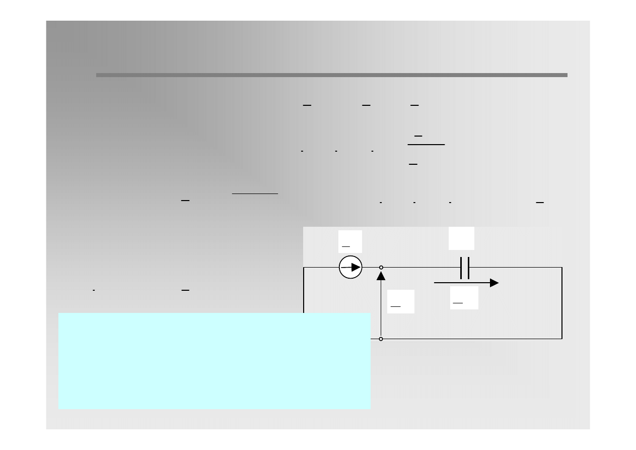
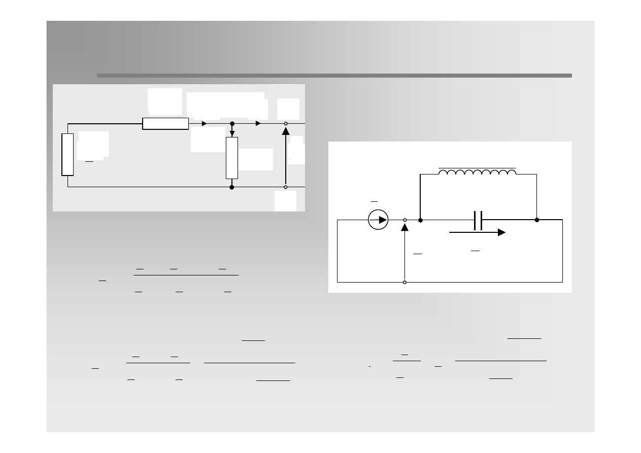
Furthermore, assuming that
one can write
Since
thus
Phase current:
Simplified equivalent circuit for
single-phase short-circuit in
isolated network
The capacitive earth-fault current is significantly lower
than a typical short-circuit current, in most cases even
lower than the normal operating current. The single
phase fault in a system with isolated neutral is called
earth-fault instead of short-circuit.

8 / 31
Voltage
Voltage
at
at
short
short
-
-
circuit location
circuit location
( )
( ) ( )
( )
( )
( )
( )
1
0
0
0
1
0
0 Y
E
U
Z
I
Z
E
Z
= −
= −
= −
( )
( )
( ) ( )
( )
( )
( )
( )
( )
1
1
1 1
1
1 X
1
1
0 Y
E
U
E
Z I
E
Z
E
Z
=
−
=
−
≈
( )
( ) ( )
( )
( )
( )
1
2
2
2 X
2
0 Y
E
U
Z
I
Z
0
Z
= −
= −
≈
( )
( )
( )
R
0
1
2
U
U
U
U
0
=
+
+
=
( )
( )
( )
( )
( )
( )
o
2
2
j210
1
1
S
0
1
2
U
U
a U
a U
a
1 E
3 E e
=
+
+
=
−
=
( )
( )
( )
(
)
( )
( )
o
2
j150
1
1
T
0
1
2
U
U
a U
a U
a 1 E
3 E e
=
+
+
== −
=
Voltage sequence components at short-circuit location:
Phase voltages:
9 / 31
Earth
Earth
-
-
fault
fault
current
current
in
in
isolated
isolated
network
network
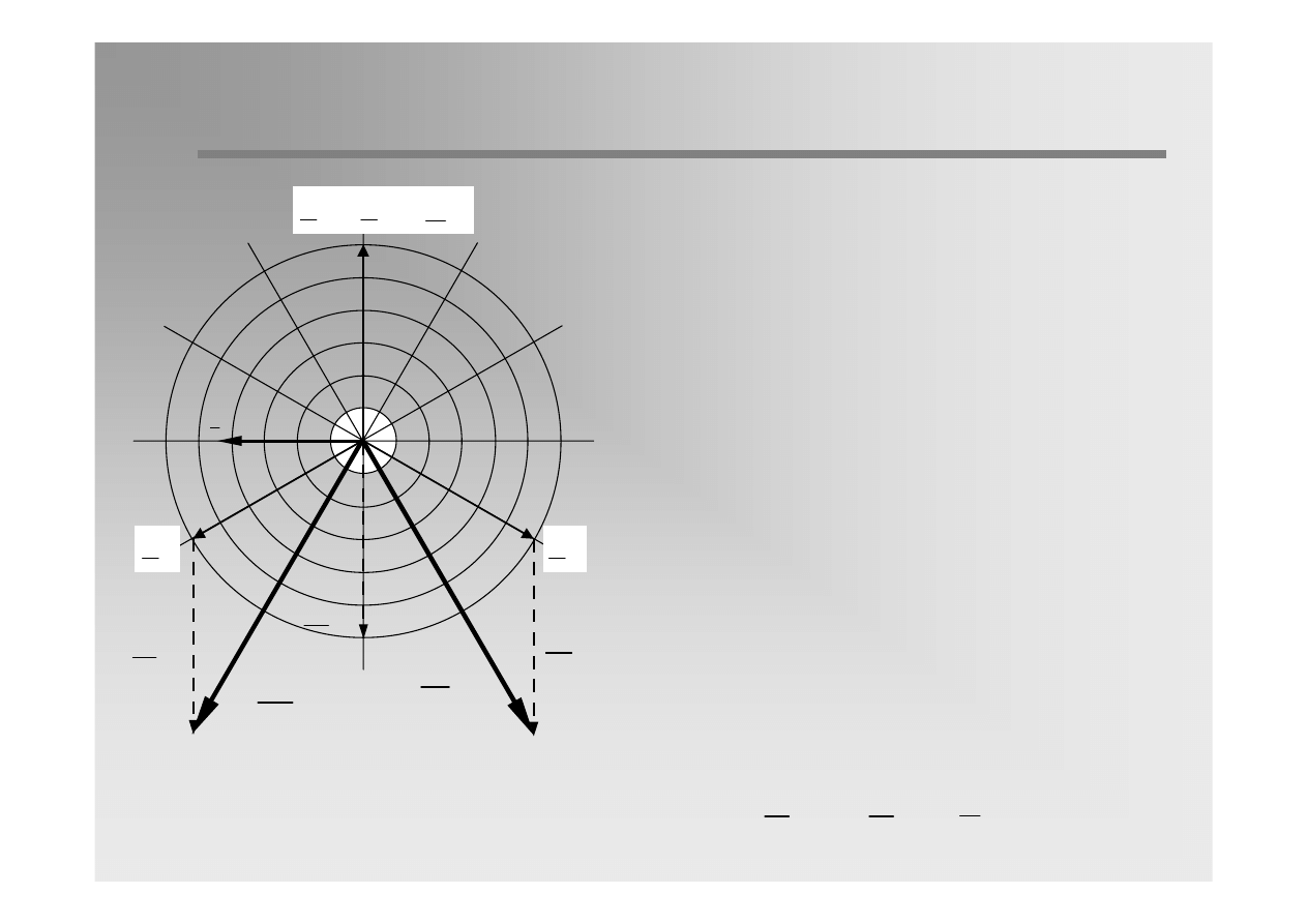
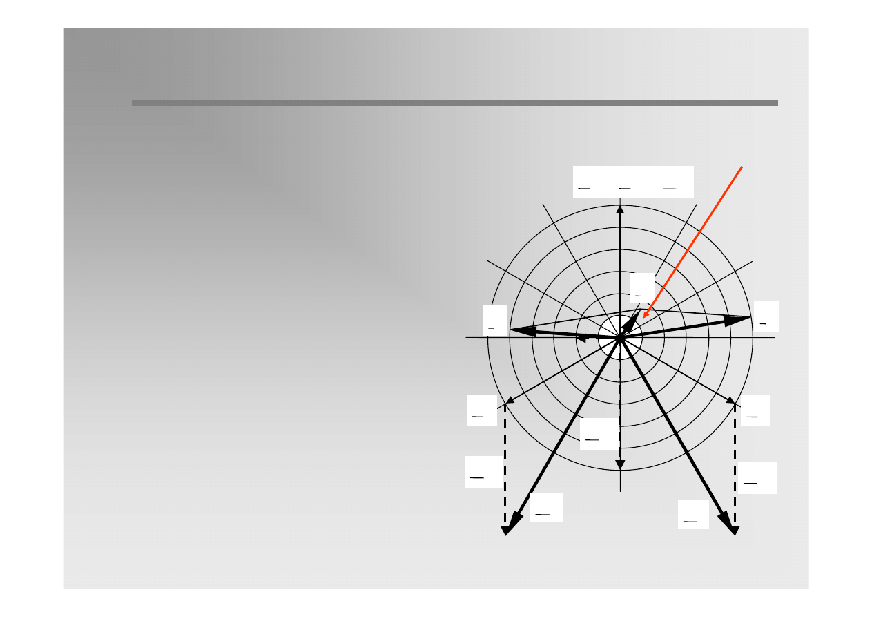
Vector diagram of voltages and currents in
short-circuit location during earth-fault.
( )
( )
1
1
R
U
E
E
=
=
S
E
T
E
R
I
( )
0
U
( )
0
U
S
U
( )
0
U
T
U
( )
( )
1
0
u
E
U
U
=
−
=
The phase-to-earth voltages of the non-faulted
phases are increasing to the amount of the
phase-to-phase voltage.
The voltage of the faulted phase is identical to
the voltage of the earth.
The voltage potential of the neutral N is given,
by definition, as the mean value of the three
phases which is not changed by the earth
fault.
A voltage displacement between neutral and
earth equal line-to-earth voltage is originating
from the fault. The voltage displacemnet is
equal to the voltage of the zero sequence
component.

10 / 31
Network operation during earth
Network operation during earth
-
-
fault
fault
Advantages
Typically, earth fault is an intermittent arc fault. Since fault currents are small
they can be extinguished by themselves. Exterior factors like wind or cable
isolation are favourable to that.
As a result of self-extinguishing most earth-faults disappear spontaneously
(70% in overhead lines 20-30% in cable lines).
Three voltages phase-to-phase remain symmetrical. As a result, in LV network
phase and line voltages are the same before and after a fault. Consumer
devices operate normally.
The low value of fault current and the lack of disturbances in load operation
make the long operation of network with earth-fault possible.

11 / 31
Network operation during earth
Network operation during earth
-
-
fault
fault
Disadvantages:
Phase voltages at non-faulted phases increase to the value of
√3 U
f
Persistent arc, which ignites and extinguishes at every current zero-
crossing causes transient overvoltages of multiplication factor (2÷3,5) U
f..
Due to the system damping, the overvoltage factor will be below 3 in most
of the cases.
The capacitive earth-fault current and the recovery voltage at the fault
location have a phase displacement of nearly 90º. The earth-fault arc is
extinguished app. 10 ms after ignition of the earth-fault when the current
has its zero-crossing. At the same time the voltage at the faulted phase
reaches peak value (due to displacement) and may cause a reignition of the
earth-fault.
The repetition of fault is possible. In case of double earth-fault short-circuit
current is similar to two-phase fault (app. 0,87 of 3-phase fault).

12 / 31
Network operation during earth
Network operation during earth
-
-
fault
fault
Disadvantages:
As an effect of arc burning the following phenomena can occur at the fault
location:
•
Melting of conductors, destruction of insulators
•
Disturbances in protection operation
•
Possibility of the smelting of active iron in electric machines
Single-phase faults cause the hazard of electric shock for the sake of touching
voltages occurrence.
Earth-fault currents can cause smelting the armaments of reinforced concrete
poles.
In overhead lines it can be observed that the impedance of ground round the
poles (pylon) incerases its resistivity (evaporation of water, slag forming).

13 / 31
Network operation during earth
Network operation during earth
-
-
fault
fault
The earth-fault value depends
on the type of network and
increases with increasing line
length:
Wire
cross-
section
mm
2
Line nominal voltage
6 kV
10 kV
15 kV
30 kV
Belted cable
70
0.130
0.120
0.087
0.056
95
0.145
0.130
0.100
0.060
Single-phase screend cable
70
-
-
0.185
0.133
95
-
-
0.198
0.141
Overhead lines
0.003
(
)
[ ]
Z
N
k k
n n
N
k
n
I
U k l
k l
U (0,1l
0.003l )
A
=
+
≅
≅
+
l
k
– total cable line length
l
n
– total overhead line length
k – coefficients (table) [A/kV km]
The value of current does not
depend on fault location in the
network.
14 / 31
Earth
Earth
-
-
fault
fault
through an arc
through an arc
Short-circuit current in the fault location
( )
( )
( )
( )
( )
( )
( )
(
)
2 2
1
0
0
0
1
2
2 2
0
0
j C
C
3R
E
I
E
1
1
C
3R
3R
j C
τ
τ
τ
ω
+ ω
=
=
+ ω
+
ω
( )
(
)
2
2 2
0
1
C
3R
1
τ
+ ω
≈
( )
0
1
3R
C
τ
<<
ω
( )
( ) ( )
( )
( )
2 2
0
1
1
0
0
I
j C E
C
3R E
τ
= ω
+ ω
Taking into account:
The following equation can be obtain:
( )
1
E
( )
1
U
( )
0
U
τ
R
3
( )
0
C
C
(0)
15 / 31
Earth
Earth
-
-
fault
fault
through an arc
through an arc
Voltage at short-circuit location
( )
( )
1
1
R
U
E
E
=
=
S
E
T
E
R
I
( )
0
U
R
U
S
U
T
U
( )
( ) ( )
( )
( ) ( )
( )
( )
(
)
( )
( )
( )
0
0
0
2 2
1
1
0
0
0
1
1
0
U
Z
I
1
j C E
C
3R E
j C
E
j C
3R E
τ
τ
= −
=
= −
ω
+ ω
=
ω
= −
+ ω
( )
( )
( )
( )
(
)
( )
2
2 2
0
1
1
R
0
0
U
3I R
j C
3R E
C
3R
E
τ
τ
τ
=
= ω
+ ω
16 / 31
Earth
Earth
-
-
fault flow
fault flow
A
B
L
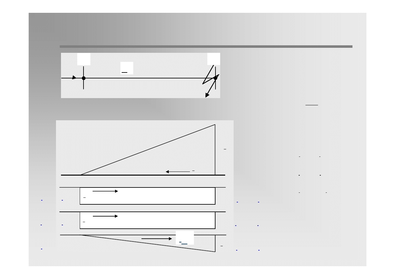
( )
( )
( )
( )
( )
( )
( )
( ) ( )
1
1 A
1
1 Y
1
1
1
1 YA
1 Y
U
I
I
Z
E
I
I
I
Z
=
+
=
=
+
=
+
( )
( )
( )
( )
( ) ( )
2
2 A
2
2
0
2 Y
U
I
I
I
I
Z
=
+
=
=
( )
0 A
I
0
=
( )
1
I
( )
1
E
( )
x
1
Z
( )
1
U
( )
x
2
Z
( )
2
U
P
(1)
K
(1)
K
(2)
( )
x
0
Z
( )
0
U
K
(0)
( )
X
1
I
( )
Y
1
I
( )
0
I
P
(0)
( )
X
0
I
( )
Y
0
I
( )
2
I
P
(2)
( )
X
2
I
( )
Y
2
I
( )
Y
0
Z
( )
Y
2
Z
( )
Y
1
Z
u
Z
3
I
(1)
I
(2)
I
(0)
I
(0)A
I
(2)A
I
(1)A

17 / 31
Earth
Earth
-
-
fault flow
fault flow
( )
( )
( )
( )
1
(1)
1 YA
1
1 Y
E
I
j C E
Z
=
= ω
( )
( )
1 Y
1
1
Z
j C
=
ω
( )
( )
0
1
C
C
<
( )
( ) ( )
( )
( ) ( )
0
1
1
0
1
1 Y
I
j C E
I
j C E
= ω
<
= ω
Line charging current:
Usually
Then earth-fault current is lower than line charging current.
In next considerations the charging current will be omitted.
18 / 31
Earth
Earth
-
-
fault flow
fault flow
( )
1
s
m
1
C
=
γ − γ
[
]
s
2h
lg
r
km/ F
0,02415
⎛
⎞
⎜
⎟
⎝
⎠
γ =
μ
Maxwell coefficients
:
h – mean height of hanging of phase wire above the ground
r – wire cross-section
H – mean distance of phase wire from the mirror reflection of other wires in earth
b
sr
– mean distance between wires
( )
0
s
m
1
C
2
=
γ + γ
[
]
sr
m
H
lg
b
km/ F
0,02415
⎛
⎞
⎜
⎟
⎝
⎠
γ =
μ
Positive and zero sequence capacitance of the line:
19 / 31
Earth
Earth
-
-
fault flow
fault flow
( )
0
I
( )
2
I
( )
1
I
( )
0
I
3
( )
0
I
Z
I
(1)B
(0)
I
I
=
( )
( )
1 A
'
0
I
I
=
( )
( )
2 A
'
0
I
I
=
( )
0 A
'
I
0
=
A
B
L
Earth-fault current
(2)B
(0)
I
I
=
(0)B
(0)
I
I
=
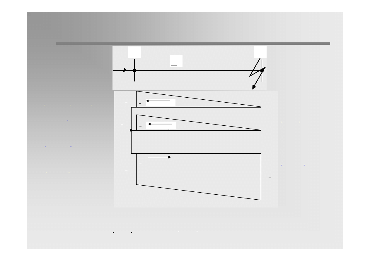
At any point α:
α
α =
A
AB
L
L
α
=
'
(1)
(0)
I
I
α
=
'
(2)
(0)
I
I
α
= α
'
(0)
(0)
I
I
I
(0)
20 / 31
Earth
Earth
-
-
fault flow
fault flow
RB
(0)
I
3I
=
SB
TB
I
I
0
=
=
'
RA
(0)
I
2I
=
'
2
SA
(0)
(0)
(0)
I
a I
aI
I
=
+
=
= −
'
TA
(0)
I
I
= −
A
B
L
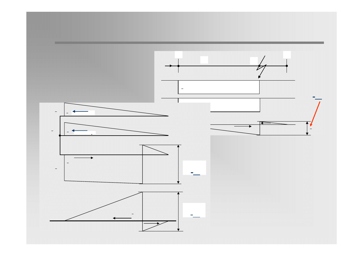
Phase currents:
α
=
+ α
'
R
(0)
I
I (2
)
α
=
α −
'
S
(0)
I
I (
1)
α
=
α −
'
T
(0)
I
I (
1)
'
T
I
'
S
I
'
R
I
( )
0
I
3
( )
0
I
−
( )
0
I
−
( )
0
I
2
At any point α:
21 / 31
Earth
Earth
-
-
fault flow
fault flow
A
B
L
K
( )
1
I
( )
2
I
( )
0
I
I
(0)
'
T
I
'
S
I
'
R
I
( )
0
I
3
( )
0
I
−
( )
0
I
−
( )
0
I
2
( )
0
I
3
Z
I
3I
(0)
3I
(0)

22 / 31
Earth
Earth
-
-
fault flow
fault flow
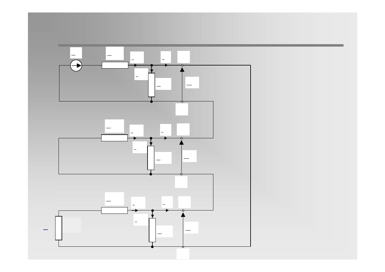
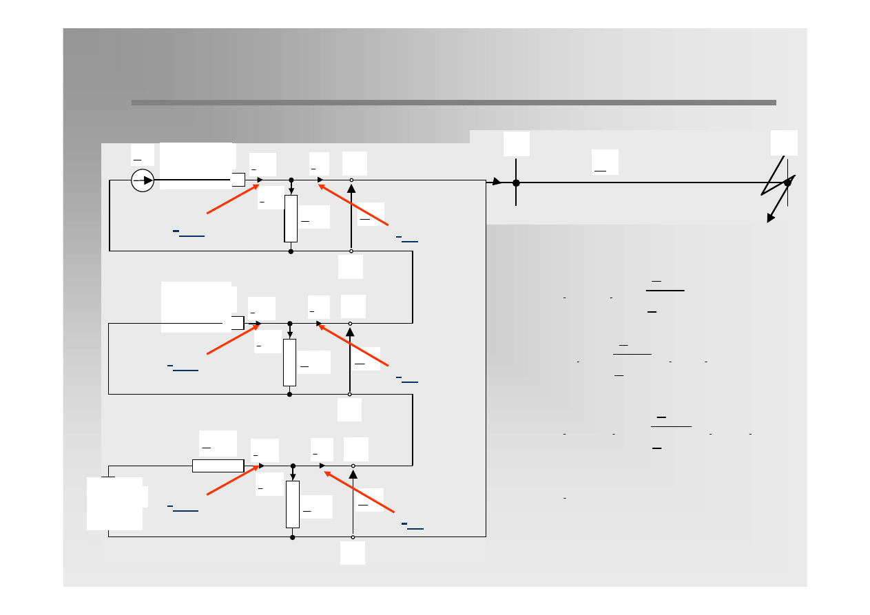
Principles of short-circuit current flow
Earth-fault current is equal 3 times zero sequence current. It flows
through the earth, zero sequence admittances, line wires and
transformer windings.
1.
Currents in non-faulted phases increases along the line from zero at
the end to the value of I
0
at the beginning.
2.
Current in faulted phase increases along the line from zero at both
ends to the value of I
0
at the fault location. Moreover, through the
faulted phase wire the sum of non-faulted phase currents 2 I
0
is
flowing to the fault location.
3.
Earth-fault current 3I
0
is flowing in earth from the fault location to the
end points of the line, where it reaches zero value.
23 / 31
Resonance
Resonance
earthing
earthing
Resonanse earthing is applied if earth-fault current exceed limit values.
Resonance earhing is realized by earthing of one or several neutrals of
transformers through reactances (Petersen-coils), normally adjustable,
which will be set in resonance to the phase to earth capacitances of the
system.
The system in widely in
operation in Europen
countries in MV networks.
24 / 31
Resonance
Resonance
earthing
earthing
( )
x
0
Z
(
0
U
K
(0)
( )
0
I
P
(0)
( )
X
0
I
( )
Y
0
I
( )
Y
0
Z
u
Z
3
Z
(0)Y
Z
(0)X
u
u
Z
j L
= ω
(0)Y
(0)X
u
(0)
(0)Y
(0)X
u
Z
(Z
3Z )
Z
Z
Z
3Z
+
=
+
+
u
(0)Y
u
(0)
(0)
(0)Y
u
u
(0)
L
3
Z
3Z
C
Z
1
Z
3Z
j(3 L
)
C
=
=
+
ω −
ω
u
(1)
(0)
R
(1)
u
(0)
(0)
1
j(3 L
)
3E
C
I
E
L
Z
C
ω −
ω
≅
=
( )
1
E
( )
1
U
( )
0
U
( )
0
C
u
L
3

25 / 31
Resonance
Resonance
earthing
earthing
At the state of resonance the value of earth current is equal zero.
u
(0)
1
3 L
0
C
ω −
=
ω
=
=
ω
ω
u
u
2
(0)
(0)
1
1
L
or X
3 C
3
C
L
C
I
k
1
I
=
>
Then
so:
In order to avoid high overvoltages in case of exact resonance tuning
a small overtuning of up to 10 percent is recommended in practice,
resulting in an ohmic-inductive residual current at the fault location.
The Petersen coil can only be tuned for one frequency in resonance. Harmonics present
in the system voltage are increasing the residual current at the faul location.
26 / 31
Resonance
Resonance
earthing
earthing
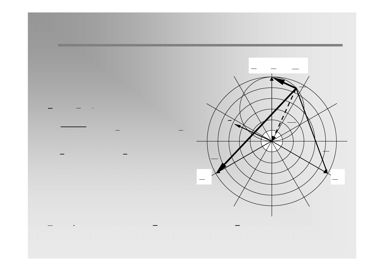
Vector diagram for the state of overtuning, with
taking into account ohmic components of
capacitive and inductive currents.
( )
( )
1
1
R
U
E
E
=
=
S
E
T
E
S
U
T
U
( )
0
U
( )
0
U
( )
0
U
C
I
L
I
r
I
Residual current
The task of resonance earthing is to reduce
the earth-fault current at the fault location to
the minimum or nearly to the minimum by
adjusting the Petersen coil to resonance or
nearly to resonance with phase-to-earth
capacitances. The omic part of the residual
current cannot be compensated by this. If
residual current is small enough, a self-
extinguishing of the arc is possible.
As the phase-to-earth capacitances are
changing during system operation, eg. due
to switching of lines, the Petersen coil has
to be also changed.
27 / 31
Resonance
Resonance
earthing
earthing
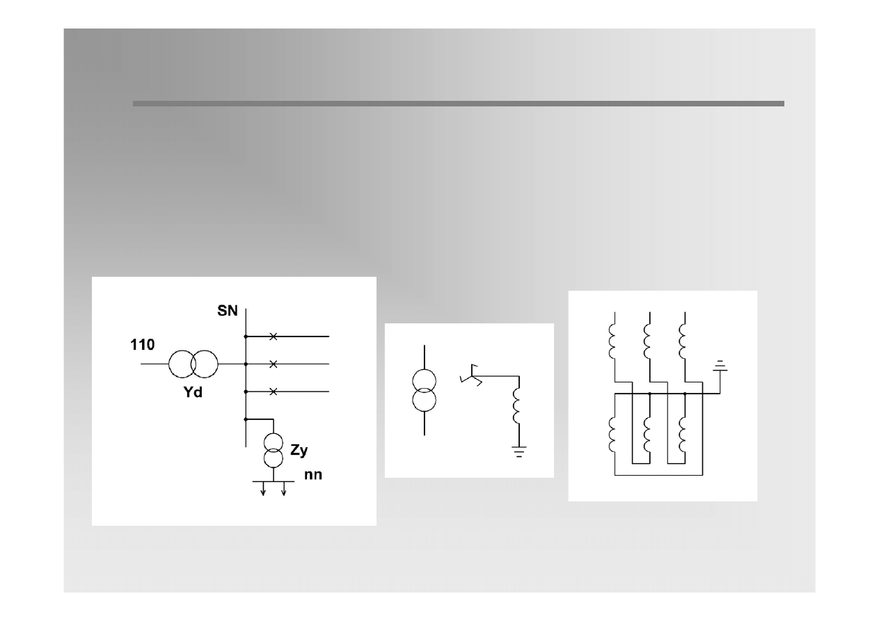
Compensated network has the characteristics similar to isolated
network characteristics, however the conditions for self-extinguishing
are better because of lower current value.
Petersen coil is connected to the earth through grounding transformer.
28 / 31
Resonance
Resonance
and
and
resistance
resistance
eathing
eathing
(AWSC)
(AWSC)
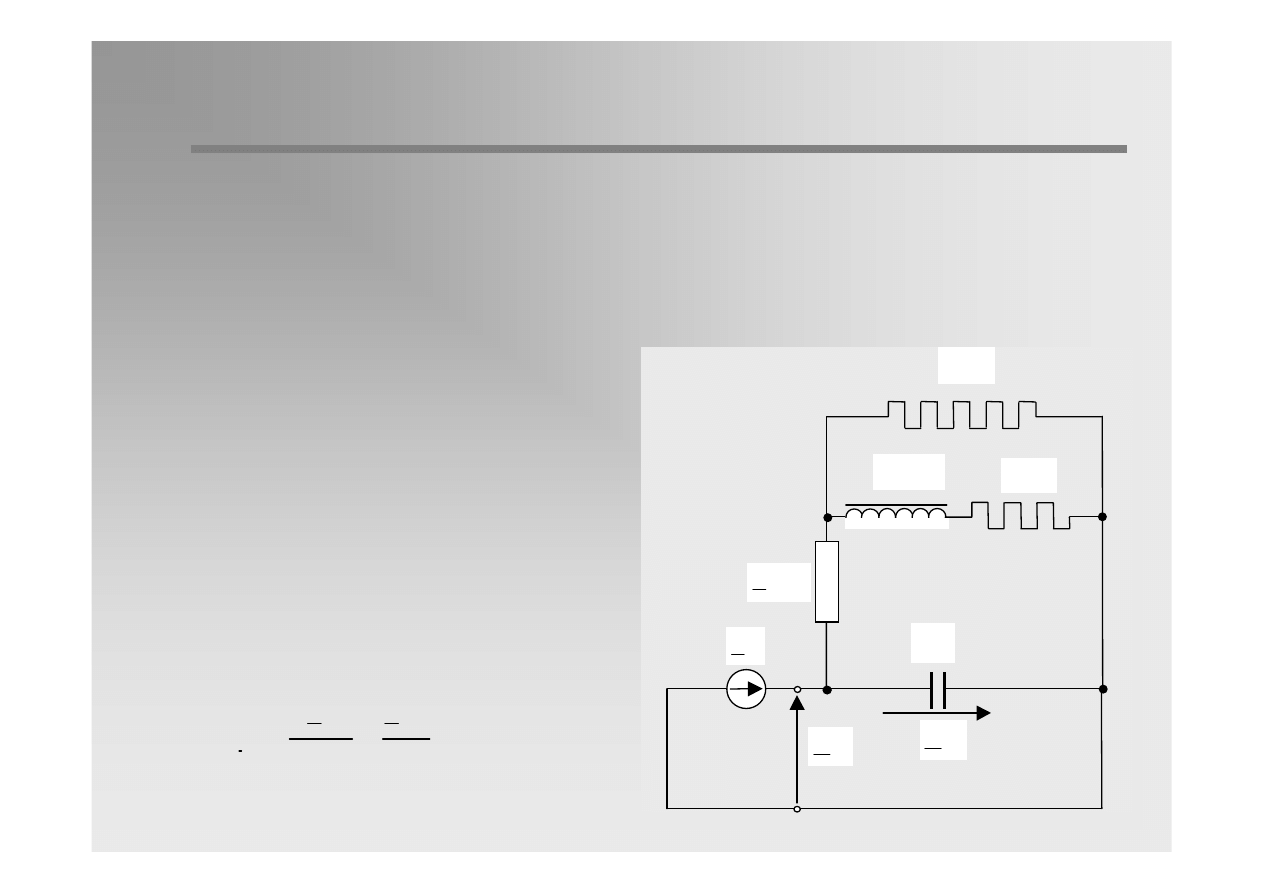
Normally, the network operates with resonace earthing. If the earth-fault
current is not self-extinguishing after a few seconds from the beginning of
a fault a resistor is connected in parallel with Petersen coil in order to
force ohmic component of the curent and prompt protection to operate.
W
R
3
( )
1
E
( )
1
U
( )
0
U
( )
0
C
K
L
3 ω
K
R
3
( )
TU
0
Z
( )
( )
1
1
R
W
W
3E
E
I
3R
R
=
=
At the state of resonance tuning:
Automatics of ohmic
current component forcing
– AWSC (in Polish)
29 / 31
Resonance
Resonance
and
and
resistance
resistance
eathing
eathing
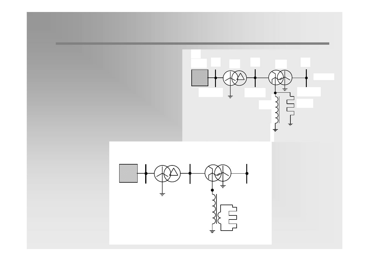
TZ
A
B
15 kV
0.4 kV
TU
D
110 kV
UE
DU
RW
a)
TZ
A
B
15 kV
0.4 kV
TU
D
110 kV
UE
DU
RW
b)
This manner joins the
advantages of compensation in
the field of fault elimination with
advantages of low-impedance
earthing in the field of correct
protection performance.
30 / 31
Earthing
Earthing
with
with
current
current
limitation
limitation
( )
1
E
( )
1
U
( )
0
U
( )
0
C
U
R
3
( )
TU
0
Z
( )
( )
( )
( )
R
1
0
U
0 TU
0 TU
1
I
3E
jB
R
3R
jX
⎛
⎞
⎜
⎟
=
+
⎜
⎟
+
+
⎝
⎠
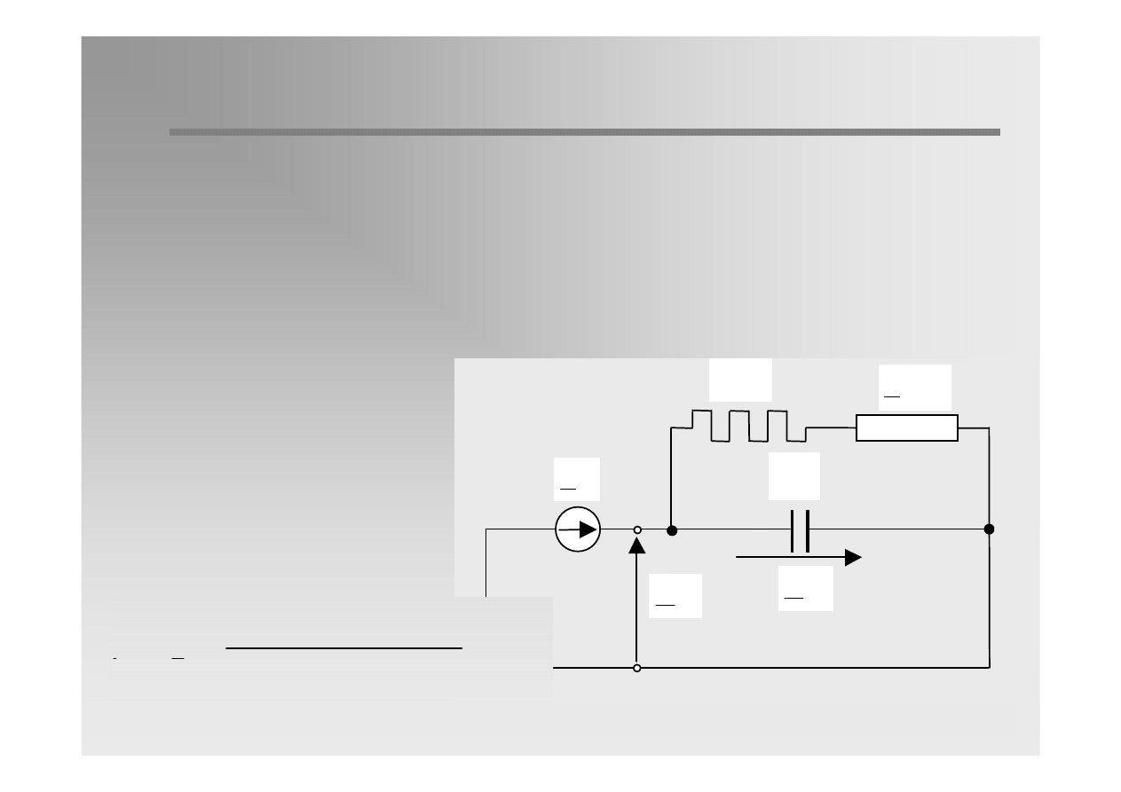
To realise the scheme of earthing with current limitation the neutrals of
some or all transformers are earthed through reactances or resistances
to such an amount that the condition for the single-phase short-circuit is
fulfilled. The criterion for the design of the earthing conditions is the value
of the single-phase short-circuit current which can be limited to some kA
comparing to low-impedance earthing.

31 / 31
MV
MV
networks
networks
–
–
summary
summary
Most MV networks operate with resonance earthing.
Advantages:
Decreasing earth-fault currents
The possibility of load supply despite a fault
Decreasing electric shock hazard and harmful effects of short-
circuit currents
Cheap solutions of earthing systems and protection
Advantages of compensation are limited by the following factors
:
Increasing the area of network
Higher harmonics in the fault-current and the lack of possibility of
their compensation
Not very precise regulation of extinguishing devices and high
residual currents which makes impossible the fault to self-
extinguish

32 / 31
MV
MV
networks
networks
–
–
summary
summary
Applied solutions:
¾
Resonance earthing and:
•
Division of large networks into smaller parts
•
Improvement of measurement methods and Petersen coils
tuning
•
Installing Petersen coils with smooth regulation under load
conditions
•
Application of forcing resistors
¾
Development of perm earthing with current limitation (mainly
through resistor)
Wyszukiwarka
Podobne podstrony:
NEUTRALIZACJA SCIEKOW id 317674 Nieznany
Abolicja podatkowa id 50334 Nieznany (2)
4 LIDER MENEDZER id 37733 Nieznany (2)
katechezy MB id 233498 Nieznany
metro sciaga id 296943 Nieznany
perf id 354744 Nieznany
interbase id 92028 Nieznany
Mbaku id 289860 Nieznany
Probiotyki antybiotyki id 66316 Nieznany
miedziowanie cz 2 id 113259 Nieznany
LTC1729 id 273494 Nieznany
D11B7AOver0400 id 130434 Nieznany
analiza ryzyka bio id 61320 Nieznany
pedagogika ogolna id 353595 Nieznany
Misc3 id 302777 Nieznany
cw med 5 id 122239 Nieznany
D20031152Lj id 130579 Nieznany
więcej podobnych podstron