10
The New Digital Direction
Do- While
Compressing Audio and Video Over the Internet
Mike Podanoffsky
The Laser Billboard
A Low-Cost Laser Image Projection System
David Prutchi
I 62
q
From the Bench
Task Manager
KBDXLATOR
Ken Davidson
A Cure for the
Odd Parity Blues
Bachiochi
Digital TV Now
q
Silicon Update
New
Product News
Radio Chip
edited by Hatv Weiner
Tom
Advertiser’s Index
Priority Interrupt
Steve Ciarcia
Nouveau PC
edited bv Harv Weiner
41
Writing Device Drivers for Embedded PCs
Simon Napper
Quarter
Motion Control with
Chuck Raskin
Applied PCs
Managing a NASA Plant-Growth Chamber
Part 1: Picking the Hardware
Fred Eady
Circuit Cellar INK@
Issue 66 September 1997
Edited by Harv Weiner
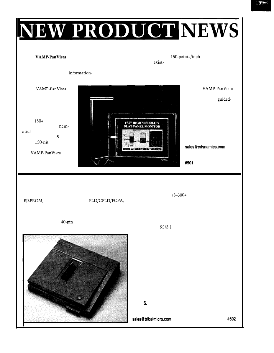
FLAT-PANEL CRT REPLACEMENT
The
is a
17.7”
and other custom analog signals. Its
resolution, z-axis
CSTN-LCD color flat-panel CRT re-
design enables the use of the
for pressure-sensitive feedback,
placement featuring 1024 x 768 (XGA)
ing computer’s video card.
and superb resistance to chemicals
resolution. Ideal for high
The guided acoustic-wave touch
and scratching. Overall system
content screens, it rivals color TFT
option affords 92% optical clarity,
dimensions for the open-frame
screens in viewing quality.
The
screen offers the viewing
area of a 21” CRT at a frac-
tion of the weight, volume,
and power consumption
(30 W, compared to the
CRT’s
W). Its color
STN (super-twisted
technology permits a
brilliant display of 12
colors,
brightness,
and a 25: 1 contrast ratio.
The
ac-
cepts standard VGA signals,
sync-on-green, composite,
model are 18.7” x 14.3” x
3.5”. The
sells for $4490, including
the 17.7” display,
wave touchscreen, and all
interface electronics.
Computer Dynamics
7640 Pelham Rd.
Greenville, SC 29615
(864) 627-8800
Fax: (864) 675-0106
www.cdynamics.com
UNIVERSAL PROGRAMMER
The ALL-11 Universal Programmer features a native
Windows interface and supports a wide range of flash,
BPROM, serial PROM
S
,
and microcontrollers. This full-featured programmer is
affordable enough for project programming but powerful
enough for the most demanding applications.
The ALL-1 1 has a
DIP socket to support de-
vices with 8-40 pins in a DIP package. Available adapt-
ers and converter sockets support devices in almost any
package configuration
pins. The programmer
connects to the serial port of any PC and communicates
at up to 115 kbps. An embedded high-speed CPU con-
trols all programming waveform generation by SMD pin
driver circuits for guaranteed accuracy in any PC envi-
ronment.
A Windows
user interface simplifies program-
ming. For example, the
AUTO
function lists all available
operations supported for a particular device. Simply
check off the desired operations and press 0
K.
For pro-
duction operation, an external YES key on the program-
mer can be used to initiate operations, and an LED by
the socket signifies that operations completed correctly.
To program another device, just insert a blank IC into
the socket and press Y
ES
again.
Priced at $1095, the ALL-1 1 measures approximately
8.5” x 9.5” and weighs less than 3.2 lbs., including a
built-in universal input power supply.
Tribal Microsystems, Inc.
44388 Grimmer Blvd.
Fremont, CA 94538
(510) 623-8859
l
Fax: (510) 623-9925
l
www.tribalmicro.com
6
Issue 86
September 1997
Circuit
Cellar
INK@

INCLINOMETER
The ISU Inclinometer
The PWM output is 30 Hz,
is a rugged, noncontact
free running, and the pulse
measurement transducer
width varies 49.3 per
that uses a capacitive
degree. The unit measures
angle sensor working in
2.6” x 1.3” x
and it
concert with a
weighs 0.8 oz. Power input
to provide a wide
is 5 VDC at 2
angular measurement
The ISU Inclinometer is
range with excellent
priced at $85. Options include
resolution and accuracy.
limited angle-range calibration,
The inclinometer comes
higher or lower accuracy versions, and
dard with both PWM and serial digital
addressability.
outputs
in addition to optional
addressability. Typical uses include wheel align-
ment, medical range-of-motion measurements, antenna
Technologies
elevation, construction equipment, and machine tools.
2030B Fortune Dr.
The ISU Inclinometer features a full 360” range with
San Jose, CA 95131
accuracy at level and plumb, and
at other
(408) 434-7000
angles. Its time constant is 0.4 (typical), and it has an
Fax: (408)
angle output rate of 533 ms. Its serial port output is
RS-232, except for voltage levels, and runs at 9600 bps.
32K
EXP
-STANDARD PC BUS
-LCD, KBD PORT
BATT. BACK RTC
IRQO-15 (8259 X2)
8237 DMA 8253 TMR
-BUILT-IN LED
-CMOS NVRAM
USE TURBO C,
BASIC,
RUNS DOS AND
WINDOWS
EVAL KIT $295
PROGRAMMER
-DOES
8 MEG EPROMS
-CMOS, EE, FLASH, NVRAM
-EASIER TO USE THAN MOST
POWERFUL SCRIPT ABILITY
MICROCONT. ADAPTERS
PLCC. MINI-DIP ADAPTERS
-SUPER FAST ALGORITHMS
OTHER PRODUCTS:
8088 SINGLE BOARD COMPUTER . . . . . . . OEM
‘95
PC FLASH/ROM DISKS
16 BIT 16 CHAN ADC-D A
. . . . . . . . . . . . . . . . . . 21 . . . . . 75
C CARD . . . . . . . . . . . . . . . . . . . . .
WATCHDOG (REBOOTS PC ON HANGUP) . . . . . 27 . . . . . 95
‘EVAL KITS INCLUDE MANUAL
BRACKET AND SOFTWARE.
MVS BOX
850
5 YR LIMITED WARRANTY
FREE SHIPPING
MERRIMACK, NH
HRS: MON-FRI
EST
(508) 792 9507
l
l
l
and
l
.
Circuit Cellar INK@
Issue 66
September 1997
7
SINGLE-BOARD COMPUTER
The CP-320 SBC is
based on the
microcontroller and
features a variety of
interface options. In
addition to a high-speed
link to a PC parallel
port, an RS-232C buff-
ered serial port, and a
bidirectional
compatible keyboard
interface, this board
features an IR data link
that operates at speeds
up to 115.2 kbps. The
card also features an
RS-485 interface for
multipoint data trans-
mission.
The
micro-
controller is an enhanced
8051 derivative. It now
features optimized
instruction execu-
tion, up to 33-MHz
clock speed, two
full-duplex serial
ports, dual data
pointers, and
fail reset. It also has
a watchdog timer,
13 interrupt sources,
and enhanced stop
and idle operation.
The board measures
4.5” x 6.5” and in-
cludes either 32 or
64 KB of EPROM,
32 KB of battery-backed
tors bring out various board
Allen Systems
SRAM,
PPI, and a
resources.
2346
Rd.
DS1232 processor
The
version of
Columbus, OH 43221
chip. In addition to the
the CP-320 sells for $219. A
(614) 488-7122
PC interface connectors, a
version is available
number of header
for $179.
FEATURES
HDTV
The New Digital Direction
Compressing Audio and
Video Over the Internet
The Laser Billboard
HDTV
A Low-Cost Laser Image
Projection System
Do-While Jones
The New Digital Direction
n rare occasions,
decisions are made
that affect nearly every
body. Some people win;
some people lose. The bigger the change,
the bigger the opportunity and the
bigger the danger.
The invention of the personal com-
puter was one of those things. Bill Gates
took full advantage of it. You didn’t, so
nobody talks about your bad haircut.
But now, there’s a second chance at a
once-in-a-lifetime opportunity. In 2006,
all the televisions in 96 million Ameri-
can homes become obsolete. Nearly
every one of those households will buy
something new (a TV, converter, etc.).
Your mission, if you accept it, is to
build something lots of people will buy.
Of course, if you design something like
the
cartridge or Beta-format
VCR, I will disavow ever knowing you.
Seriously, the FCC’s decision to
switch to high-definition (digital) televi-
sion (HDTV) has significant impact.
For example, you won’t be able to
show any
camcorder home videos
on an HDTV unless you have a con-
verter or one built into your set. Your
present VCR doesn’t work with HDTV,
so you need a new one to record your
soaps and watch them after work.
But, I’m not going to tell you what
to design or buy. The technical issues
are far too intricate to explain here.
10
Issue 88 September 1997
Circuit Cellar INK@
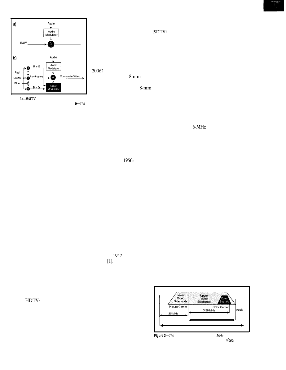
Luminance
Video
Composite Video
Figure
signals consist of a luminance signal
with audio modulating a high-frequency carrier.
red, green, and blue signals from a color camera combine
to form a luminance signal. Two chrominance signals,
consisting of two of the three color signals, modulate a
high-frequency color carrier and are added to the lumi-
nance to create a composite video signal.
Instead, I want to give you a general
understanding of the issues.
Digital TV frees us from some limi-
tations that resulted from the need to
be compatible with technology of the
1950s. The change, however, is not
without difficulties.
CONSIDER THE QUESTIONS
The practical ramifications of the
switch to HDTV aren’t generally under-
stood-even by professionals.
I interviewed TV and satellite-dish
employees after the FCC announced
its decision to convert from analog to
digital TV. Not one fully understood
the compatibility problems involving
camcorders, VCRs, and cable boxes.
A cable-TV manager’s response was
most surprising. He said 50% of his
customers have cable-ready TVs or
VCRs because they don’t want to mess
with a cable box. Only those wanting
pay-per-view or premium channels
have boxes, and they don’t like them.
When TV stations switch to HDTV
in 2006, he plans on converting digital
video at the station and broadcasting
good old NTSC analog video. He may
change his mind if the customers who
bought
drop his cable service
and buy satellite dishes instead.
What will your cable company do?
Broadcast analog video and add HDTV
channels as they become available?
After 2006, will they drop the analog
or convert HDTV to analog and broad-
cast both converted video and HDTV?
Do you own a satellite dish? It can
blue light coming from the scene.
already decode MPEG-2-encoded stan-
Color-TV sets produce three pictures (a
dard-definition digital television
red, green, and blue] so close together
but what about MPEG-2 HDTV? Will
that they are virtually on top of each
you completely replace your receiver,
other. If you mix “equal” amounts of
or will someone sell software that
red, green, and blue light, you get
makes the receiver HDTV compatible?
white light.
Do you have home videos of birthday
parties? How will you watch them after
Will you keep an old TV and VCR
(stored beside your
movie projec-
tor) for this? Will you pay someone to
convert your videos and
movies
to HDTV-format video tapes or disks?
These are just a few of the far-reach-
ing implications of the format change.
To make intelligent decisions, you
need to understand the reasons for the
changes and the compromises made by
the various solutions.
Adding the red, green, and blue pic-
tures together creates a luminance
signal like the one produced by a B/W
camera. Of course, a color set separates
the luminance back into red, green, and
blue signals. Two added chrominance
signals let the TV set do this. Figure lb
shows the general method. (I’m fibbing
a bit here, but you’ll get the truth later.)
Perhaps the easiest-and most enter-
taining-way to understand the techno-
logical issues is to follow the history of
TV in America. The performance of
today’s sets is poor because they’re
compatible with
technology. Let’s
look at the foundation that determined
how the entire structure came to be.
The video signal is applied to an RF
modulator whose frequency depends on
the broadcast channel. Each channel is
allowed a
bandwidth. Channel 2
is 54-60 MHz, channel 3 is 60-66 MHz,
and so on.
There’s a gap between channels 6
and 7 because that’s where FM radio
stations are. But typically, channels
are 6 MHz wide and 6 MHz apart.
COLOR COMPATIBLE
In the old B/W days, the video signal
The modulation technique is Vesti-
gial Side Band (VSB). All the upper side
bands are transmitted, but only some of
the lower side bands are. This cuts the
transmission bandwidth almost in half.
(luminance) was added to the audio
signal. The audio signal modulated a
4.5MHz carrier and could be separated
from the video with a high-pass filter.
The combined signal, or composite
video, is shown in Figure la.
Figure 2 shows the lop-sided frequen-
cy spectrum of the broadcast signal. In
other words, old B/W TV signals had
4.5 MHz of upper sidebands, which
produced sharp, clear pictures.
Color TV introduced a difficult prob-
lem. There were lots of B/W TVs-not
as many as the 200300 million there
are today, but quite a few nevertheless.
The new color-TV sacrificed some
clarity by taking away bandwidth to add
color. This was necessary to retain com-
patibility between color and B/W video.
The number of TV sets went from
137,000 in
to more than 7 million
in 1957
Stations didn’t want to
broadcast in color if the programs could
not be seen on B/W TVs, and people
wouldn’t buy color TVs if they couldn’t
watch their favorite B/W
programs.
The broadcast video goes from the
transmitting antenna to the receiving
antenna and into the TV tuner. The
tuner demodulates the signal to obtain
the composite video signal. Now, let’s
see what happens to the composite
video for the color and B/W cases.
To solve this dilemma,
they took advantage of the
fact that the three primary
colors of light (red, green, and
blue) can be mixed to produce
any color in the rainbow,
including white.
Color-TV cameras measure
4.5 MHz
6 MHz
the amount of red, green, and
composite video signal uses 6
The co/or signals
occupy
some of the bandwidth formerly used by B/W
Circuit Cellar INK@
Issue 86 September 1997
11
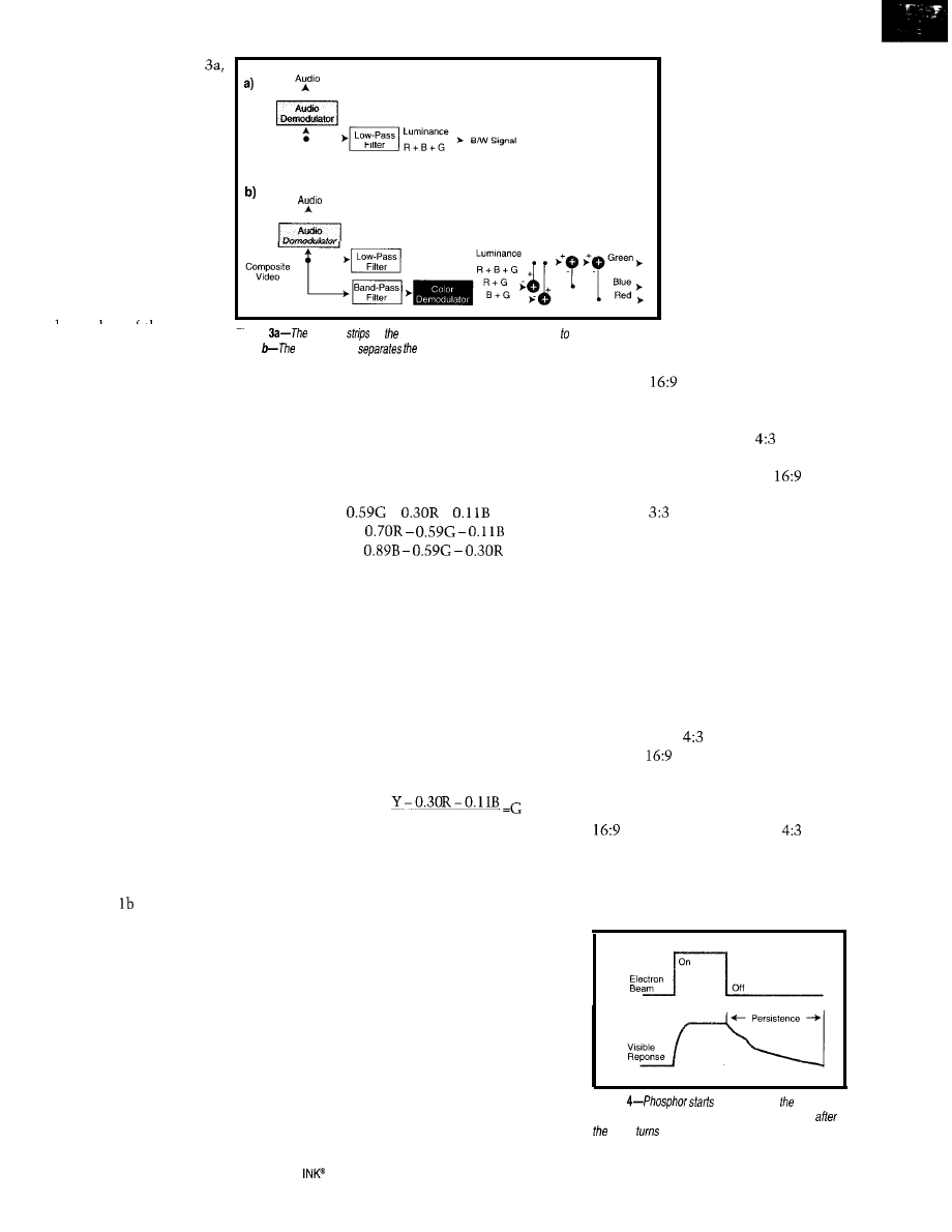
As depicted in Figure
B/W TV just strips off the
audio signal and uses the
remaining composite video
as the luminance signal. It
doesn’t process the color
signals because the B/W
circuits were built before
color TV was invented.
In old B/W TVs, the
low-pass filter rejected the
audio carrier, not the color
signals. The high-frequency
color signals cause the
Composite Video
RGB Video
snarp eages or tne picture
Figure
to
be a little fuzzier, but
B/W TV
off audio and uses the rest of the signal modulate the picture
tube.
color circuitry
composite video info ifs red, green, and blue aspects.
most people don’t notice
the degradation in quality.
The luminance signal (i.e., Y) gives
each color a different weight. So, the
two chrominance signals (i.e., R-Y and
B-Y) must be specially weighted sums
so they can separate the luminance
into red, green, and blue signals:
space. A
rectangle (16 units wide
x 9 units high) wastes a lot of space on
the top and bottom.
Figure 3b illustrates how color-TV
circuitry separates the composite signal
back into its red, green, and blue com-
ponents. The low-pass filter extracts the
luminance, which contains the three
color signals added together.
The band-pass filter extracts color
signals from the upper portion of the
spectrum and gives them to the demod-
ulator. It extracts the two chrominance
signals that separate the colors again.
In this simplified diagram, one of the
chrominance signals contains red and
green information. The other holds blue
and green. Subtracting the red and green
chrominance signals from luminance
yields the blue signal. Subtracting blue
and green yields red. And, of course,
subtracting red and blue yields green.
The red, green, and blue signals go to
the red, green, and blue guns in the color
picture tube. If the input signal is B/W,
then there are no chrominance signals
and the R+G and B+G signals are 0. The
red, green, and blue signals are all equal
to the luminance, so the color TV pro-
duces a B/W picture.
Figures and 3b aren’t entirely
accurate. In practice, it’s more compli-
cated. Adding equal amounts of red,
green, and blue signals doesn’t produce
a signal that looks exactly like a B/W
luminance signal.
A real B/W signal is more sensitive to
green because our eyes are more sensi-
tive to green. I ignored this in Figures lb
and 3b to show how one intensity and
two color signals produce a B/W-com-
patible color signal. Now you have the
concept, I can risk telling you the truth.
Y =
+
+
R-Y =
B-Y =
Y, R-Y, and B-Y are the signals that
come out of the S-Video connector on
a satellite-dish receiver or high-end
VCR. (For a slightly different formula-
tion of these equations, see Mike
Podanoffsky’s “Compressing Audio
and Video Over the Internet” in this
issue.)
Adding Y to R-Y produces R. Adding
Y to B-Y produces B. And, knowing R
and B, lets you compute:
0.59
R, G, and B are the signals that modu-
late the red, green, and blue of color TV.
But, you probably want to know how
the RGB signals produce a color picture.
The various mechanisms each set some
limits on the picture’s maximum reso-
lution, so let’s put off this discussion
until we talk about resolution limits.
ASPECT RATIO
The first picture tubes were round
because they were easier to build than
rectangular ones. The ideal format for a
round tube is a circular picture, but it
needs a spiral scan. It’s easier to design
and build a system that scans a rectan-
gular area horizontally
and vertically.
The best rectangle,
from a round picture
tube’s point of view, is a
perfect square. Most
people prefer rectangles
because more interesting
information lies to the
left and right of center
than above and below it.
We live in a world where
more things are laid out
horizontally than verti-
cally.
A square fits in a circle
with the least wasted
As a compromise, the
aspect
ratio rectangle was chosen. It gives
more viewing area than the
rect-
angle and is more pleasing to the eye
than the
square.
Modern picture tubes are rectangu-
lar rather than circular. They don’t
waste space at the top and bottom.
The first rectangular picture tubes
were measured diagonally so they could
be accurately compared with the pre-
dominant round picture tubes of the
day, which were specified by diameter.
We still use this measuring technique.
Since we can now make picture tubes
in any shape, there’s no reason to stick
with the ugly
aspect ratio. HDTV
uses the
aspect ratio, which is more
visually pleasing and more compatible
with commercial motion pictures.
The problem is, how do you display a
aspect ratio picture on a
tube?
You have three choices-get rid of a
picture’s right and left edges, make the
picture smaller and waste space on the
top and bottom, or distort the picture.
Figure
glowing when
electron
beam hits if and continues g/owing for some time
beam
off due to oersisfence.
12
Issue
86
September 1997
Circuit Cellar
When movies are broadcast
the position of the beam in
on TV, the first approach is
. .
usually taken. Things on the
2
---
the studio’s B/W camera.
So, the horizontal- and
right and left sides of the
screen are sacrificed, and the
. . .
vertical-sweep oscillators in
- -
. . 6
the camera and TV had to be
legal disclaimer, “formatted
.
phase-locked to each other. If
to fit your television screen,”
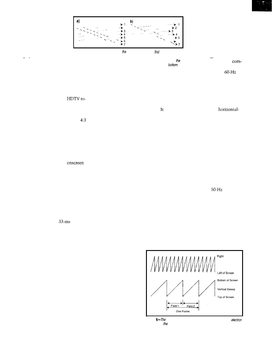
Figure Ca-An interlaced scan draws odd-numbered lines
and then draws
they weren’t, the picture
is displayed.
the second field of even-numbered lines to reduce flicker. The dotted lines show the
resembled Fieure 7.
Often, this approach can’t
horizontal retrace during the horizontal blanking period. The dashed lines show
At the time, the only
be used for the opening and
vertical retrace. &Progressive scan draws the lines in order, from top to
monly available frequency
closing credits because the lettering
goes from edge to edge. So, the picture
is then distorted. Another option is to
shrink the whole picture and add black
bars at the top and bottom.
If you’re going to build an
analog-TV converter, you must decide
whether to throw edges away or make
the picture smaller.
The early picture-tube pioneers
discovered that if the phosphor was
too slow, then moving images looked
smeared and blurry. They needed a fast
phosphor that could display rapidly
changing scenes.
When you want to display an old
home movie on a new HDTV, you have
the opposite problem. You can throw
away the top and bottom or shrink the
picture, which wastes space at the sides.
Faster is better-to a point. If phos-
phor is too fast, it has no persistence.
stops glowing as soon as the electron
beam stops shining, causing a flicker.
SCAN PROBLEMS
Pictures are rectangular-not circu-
It turned out there wasn’t a good
compromise for phosphor speed. When
the phosphor was fast enough to show
moving scenes, it flickered badly at
30 Hz. To keep the flicker down, the
screen had to be repainted at 60 Hz.
lar-because they’re painted
via a raster scan. In other words, they’re
painted in the same way you read this
magazine. You start with the line at
the top of the page, read it left to right,
move your eye down one line, back to
the left, and read the next line.
The solution was to paint 60 half
frames (i.e., fields) per second instead of
30 full frames per second (fps) via a
interlacing. All the odd-numbered lines
are painted in the first field, and the
even-numbered ones go in the second
field, as shown in Figure 5a.
American standard analog TV draws
525 lines -30 times per second (but not
all appear onscreen). So, a line is drawn
approximately every 63 us, and a frame
takes about 33 ms. This
refresh
rate causes a problem related to the
phosphor in TV picture tubes.
Phosphor glows when struck by an
electron beam. Picture-tube manufac-
turers can adjust the phosphor’s chemi-
cal formula to alter its characteristics
and make it glow red, green, blue, or
white. (Remember this fact.)
Some modern computer monitors
draw complete frames at 60 Hz using
progressive (noninterlaced) scan. This
method is shown in Figure 5b.
Whether the TV signal is analog or
digital, cathode ray tubes (
CRTS
) are
analog devices. The electron beam is
steered by magnetic fields produced by
analog voltages.
There are both horizontal- and ver-
Right now, it’s important that they
can make phosphor turn on and off
very quickly or very slowly. Adjusting
the phosphor’s speed is critical.
tical-sweep oscillators.
Figure 6 offers simplified
versions of their wave-
forms. For American TV
signals, there are 525
cycles of horizontal sweep
for every 2 cycles of verti-
cal sweep.
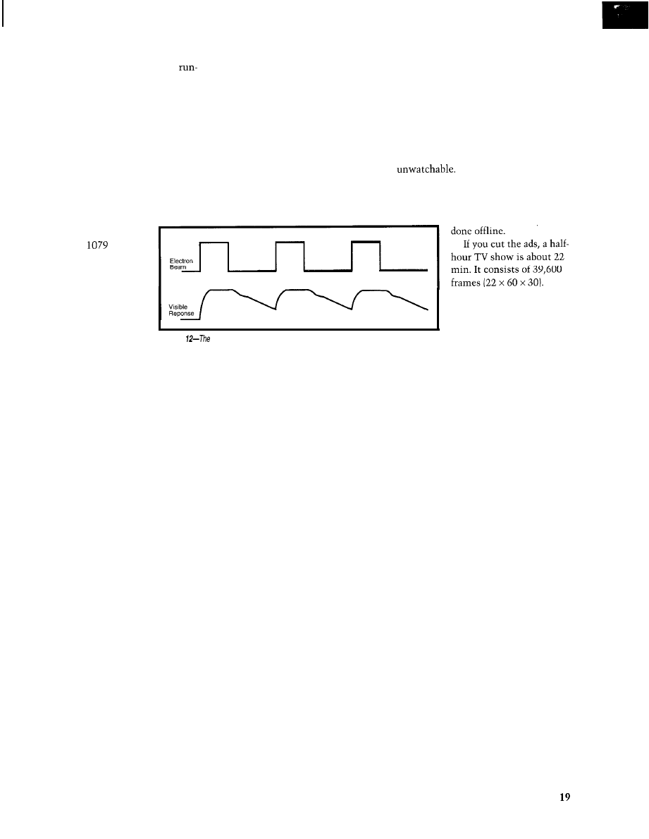
Figure 4 shows the visible response of
In TV’s early days (be-
phosphor to an electron beam. It doesn’t
fore networks and video
start glowing until the beam hits it.
tape), all programs were
And then, it takes little time to reach
transmitted live from a
full brightness. Once the beam turns
local studio. The beam
off, the phosphor glows for a while.
moving across the viewer’s
This afterglow is called persistence.
TV screen had to match
reference in America was the
power line. The TV station locked its
camera vertical-sweep oscillator to it,
as did the TV set in each viewer’s home.
A vertical-hold knob on the TV con-
trols let viewers adjust the phase to keep
the picture from rolling off the top or
bottom of the screen. The
sweep oscillator was synchronized to a
harmonic of the vertical-sweep oscilla-
tor. The user had a horizontal-hold
knob that was even trickier to adjust
than the vertical hold.
As the years went by, TV manufac-
turers built sets that automatically
locked to horizontal and vertical sync
pulses (I’11 explain shortly). No more
horizontal- and vertical-hold knobs!
The early requirement to lock the
sweep oscillators to the power line
explains why American TVs use 60 Hz.
In Europe, where the power lines use
50 Hz, the TVs have a
field rate.
Older readers will remember that the
picture used to “tear” when the channel
was changed because signals originating
from TV stations in different parts of
the country were on different power
grids running at slightly different fre-
quencies. The propagation time between
the places changed the signal’s phase.
Now, we get so many signals from
satellites and repeaters that none are
of Screen
Horizontal
Sweep
Figure
horizontal- and vertical-sweep oscillators move the
beam across screen.
1 4
Issue 86 September 1997
Circuit Cellar INK@
phase-locked to each other.
But modern
TVs phase lock before you notice it.
Color TV makes part of this possible.
Recall that Figure lb showed a color
modulator with two chrominance
inputs. It’s a synchronous modulator
whose output must be synchronously
demodulated. Every color TV must
have a
oscillator precisely
locked to the transmitter’s
oscillator. You can’t get that from a
power line! So, let’s talk about
sync pulses and color bursts.
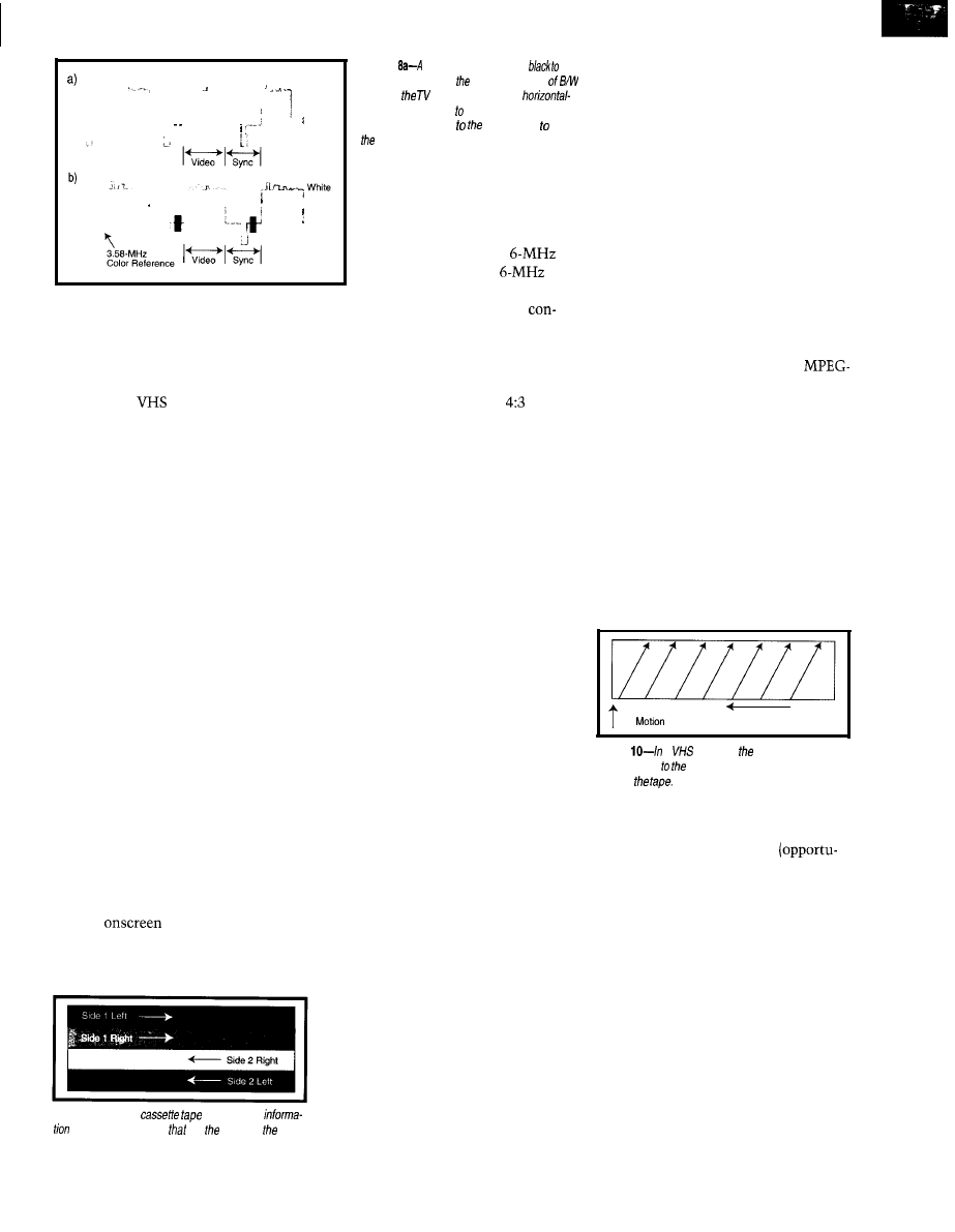
If you look at a TV signal on an
oscilloscope, you see sync pulses every
63.5 (see Figure 8a). The TV set
can’t mistake them for video informa-
tion because they go outside the range
of values from black to white.
Figure 8b shows an 8-cycle color
burst that was added to the sync pulse
so color TVs could synchronize their
color demodulator to the transmitter’s
color modulator. Every 63
the TV
adjusts its color oscillator against this
color burst. The reference signal must
be 3.579545 MHz 0.0002793%.
Since the color TV needs a precise
reference to demodulate the color sig-
nal, that reference is used to generate
the horizontal and vertical oscillators.
The horizontal scanning frequency is
exactly
times the color reference
signal (i.e., 15.7
Since there are 525 lines per frame,
the frame rate is 29.97 Hz. There are
two fields per frame, so the field rate is
59.94 Hz. Since B/W TVs use a field rate
of 60 Hz a few percent, the
rate is within a B/W circuit’s tolerance.
In Europe, there are 625 lines per
frame. Dividing the
horizon-
tal scanning frequency by 625, you get
a frame rate of 25.17 for a field rate of
50.3 Hz-very close to their power-line
frequency (not a coincidence!).
Just to muddy the waters some more,
movies are recorded on film at 24 fps.
Maybe you’ve seen old movies of Babe
Ruth hitting a home run and running
the bases. He sure could run fast!
Each frame was scanned twice to
produce two fields of video, which is
48 fields per second. But, they’re broad-
cast at 60 fields per second, so he seems
to run 25% faster than he really did.
The time compression enhances the
comic effect of silent films starring the
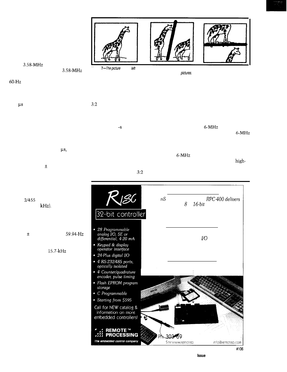
Figure
at the is
properly centered, but if the horizontal or vertical sweep oscillators are out of sync,
the picture will run off the screen
as
shown in the center and righf
Keystone Kops or Charlie Chaplin, but
it isn’t acceptable for modern films.
The reason you don’t notice the same
effect on modern films on TV is that
pull down is used. The first frame of
film is scanned three times to produce
three video fields. The second frame is
scanned twice to produce two fields.
During a 1 period, 12 film frames
are scanned three times, producing 36
video fields. The 12 film frames are
scanned twice to make another 24 video
fields (e.g., 60 video fields per second).
When they broadcast at 59.94 fields
per second, the speed error is only 0.1 %,
which isn’t noticeable. Neither is the
jitter introduced by the
pull down.
The new digital TV standard provides
for several different aspect ratios at
several different frame rates. The new
sets will have to be much more flexible,
potentially leading to a completely
new display technology.
VCR ISSUES
VCRs record
analog video.
Since HDTV occupies the same
channel as analog TV, you’d think your
present VCR could record HDTV. Sorry.
VCRs aren’t just tape recorders with
a
bandwidth. When they first
came out, a friend tried to get a
quality recording of some l-MHz signals
he was working with. It didn’t work.
Incredibly powerful
At 50
instruction time, our
the pourer that an or
controller can’t.
Inherently complete
We’ve included everything to handle even the
most demanding industrial
requirements.
Instinctively simple
Easy
to program, run,
and get
going!
O-1588, Fax: 303-690-1875
Web
corn
Circuit Cellar
INK@
66
September 1997
15
W h i t e
Black
t
Black
Figure
sync pulse goes
from
blacker-than-black at end of every line
video so can synchronize ifs
sweep oscillator (not scale). b-A co/or refer-
ence signal is added sync pulses keep
color demodulator properly synchronized.
tape every 33 ms. There, the data
was lost and the VCR tried to
insert a vertical sync pulse. That’s
why you can’t record a
digital bitstream on a
VHS
tape recorder.
You can build a VCR with a
Figure 9 shows how a standard audio
cassette-tape recorder records data along
the length of tape. It only uses half the
tape at a time so the cassette can be
flipped over to record on the other side.
verter that changes HDTV to analog TV
and records it in VHS format. It would
include another converter changing
the analog TV back to HDTV format,
but with poor quality and a
aspect
ratio. That solution may suffice for the
short term, but eventually it will be-
come unacceptable.
Although
now stands for Video
Home System, when the technology
first came out, it stood for Video Helical
Scan. The original name gives some
insight into how the recorder works.
Not only does the tape move, but the
record heads move, too. The path of the
head along the tape is helical, like lines
on an old-fashioned barber’s pole. The
video signals are recorded almost per-
pendicular to the motion of the tape,
as shown in Figure 10.
Although there are some obvious
discontinuities at the tape edges, they
don’t cause a problem for analog video.
The tape head’s motion is synchronized
with the vertical sync pulses.
Each stripe represents a whole frame.
That’s why you can push the VCR’s
pause button and see the same frame
over and over. The head is moving, but
the tape isn’t, so the same stripe gets
read again and again.
Since the tape isn’t moving, the
stripe of recorded video isn’t perfectly
aligned with the head’s motion. It scans
several adjacent stripes and the blank
space in between, producing the snow
you see
when you hit pause.
The reason my friend couldn’t get a
good recording of the l-MHz signal was
that there was a break at the edge of the
No doubt you’ve noticed that people
are so accustomed to color TV, nobody
watches B/W anymore. The day will
probably come when people are so
used to HDTV, they won’t like analog
video, either. When that day arrives,
they’ll demand digital VCRs that re-
produce HDTV perfectly.
VIDEO RAM
Most personal computers (excluding
laptops) use CRT monitors for the
screen display. The interface between
the digital data and the analog signals
moving the electron beam across the
screen is a video card that appears as
memory to the computer.
Each memory location corresponds
to a particular screen location. The
program simply writes the desired
color to that memory location, and the
video card does the rest.
The video card scans the video
memory synchronously with the hori-
zontal- and vertical-sweep signals.
Unless you
want
snow onscreen, you
better not be changing the value in
RAM at the same time as the video
card’s display circuitry is reading it!
About 10 years ago, I worked on a
system that used a video insertion card
to superimpose text on analog video.
We had to update the card only during
the vertical blanking interval when the
Figure 9-A stereo
stores audio
electron beam was moving from the
in four parallel tracks
run length of tape.
bottom of the screen to the top.
I suspect modern video cards do
that automatically now. They probably
double-buffer the data so you can write
to the buffer whenever you want. The
card transfers data from the buffer to the
video memory at the appropriate time.
The video RAM decouples the input
data rate from the display refresh rate.
I’m certainly not typing 29.97 characters
per second. The screen doesn’t flicker
every time I press a key.
The computer remembers what I
typed and updates RAM at whatever
rate I type. The video card displays it
using the proper screen-refresh rate.
The practical implication is that if I
program my computer to decode
2 compressed digital video (from a disk
file, broadcast video, the Internet, or
other source), it doesn’t matter if the
display rate matches the frame rate or
if the monitor paints the screen using
progressive or interlaced scans.
As long as the data is buffered so a
video RAM location isn’t changing
while the output circuitry scans it, there
won’t be a problem. If the frame rate is
slower than the display refresh rate
(almost certainly the case), then the
video memory automatically displays
Record Head
Tape Motion
Figure
a
recorder, record head moves
perpendicular tape, painting diagonal stripes of
data on
the last frame [or half-frame, if inter-
laced) while waiting for new data.
So, there’s more freedom
nity) for designing HDTV monitors.
Just because the monitor receives
digital information at a particular rate
(e.g., 30 Hz) doesn’t mean that the
picture tube has to be refreshed at that
rate. If it could, the monitor might
display each frame three times, re-
freshing the screen at a 90-Hz rate.
The important point is that analog
TVs had no capability to store the
picture. They had to display every pixel
the moment it was received.
Digital TVs receive compressed
blocks of information, which are de-
coded and stored in memory. The TV
1 6
Issue 86 September 1997
Circuit Cellar INK@
monitor can display the information
stored in memory any way it wants to,
as often as it wants to.
The digital-TV standard only speci-
fies how the information is encoded
and transferred. It tells how the TV
could
process the encoded information
once it is received, but it’s not required
to work that way.
THE BANDWIDTH ISSUE
Although we commonly refer to
American analog TV as having 525 lines,
not every line is displayed onscreen.
Some lines at the top of the screen
contain calibration signals. The actual
resolution is approximately 480 lines
of 640 picture elements (pixels).
The HDTV standard
lists four frame shapes
broadcast at frame rates of
23.976-60 Hz. The most talked about
is 1080 lines of 1920 pixels
aspect)
at 29.97 Hz, which has about twice as
many lines as analog TV and three
times as many pixels per line.
Since HDTV has six times as many
pixels as analog TV, you may expect it
to take six times as much bandwidth to
transmit. Since each analog TV channel
is 6 MHz, early estimates were that
digital TV would need roughly 36 MHz.
It doesn’t. It takes about 6 MHz.
How? The amount of bandwidth
required depends on the amount of
information transmitted. Sampling
Walter Chronkite’s face six times as
often doesn’t increase the information
you get from him sixfold.
Ideal for gaming, video-on-demand, multimedia kiosk and
any other multimedia application, the
multimedia card embeds
and two full COM ports in a PC/l 04 form factor.
also
full
and
support.
Other multimedia
products from
include
MPEG
cards and high bandwidth
100 Base-T CPU/LAN cards.
,
We will also do custom
multimedia embedded design.
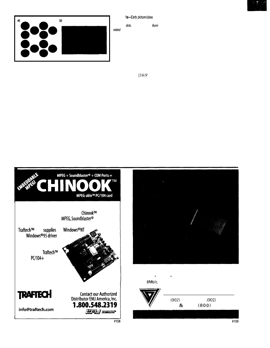
Figure 1
had
rough/y 300,000 clusters of colored
phosphor
Each color was
by a different electron beam.
b-Modem picture tubes have vertical
bands of differently colored phosphors.
Contact us now for a full catalog, or visit our Web Site!
tel 905814.1293
fax 905.814.1292
www.traftech.com
From an information-theory point
of view, each pixel in a high-definition
picture doesn’t contain as much data
as each pixel in a standard-definition
picture. That’s because the high-defini-
tion picture is oversampled.
Each sample is not statistically inde-
pendent from the ones around it. When-
ever there’s redundant information,
there’s an opportunity for compression.
The Motion Picture Experts Group
(MPEG) has defined a standard data
compression technique called MPEG-2.
Although a complete discussion of
MPEG-2 is beyond the scope of this
article, I want to go over some general
principles of data compression it uses.
You’ve probably seen a color-bar test
pattern. One style has eight vertical
bars that run white, yellow, cyan,
green, magenta, red, blue, and black.
If you transmit this pattern on analog
TV, each line is equivalent to 80 white
pixels, followed by 80 yellow pixels, and
so on. If you transmit this pattern on
uncompressed digital TV with 1920
pixels per line, it would be 240 white
pixels, followed by 240 yellow pixels,
E-Series
EPROM FLASH SRAM emulation and LIVE editing,
1 to
70ns access time. Low voltage (3v)options.
S c a n l o n D e s i g n I n c .
Tel
425 3938 Fax
425 4098
Sales Info
352 9770
18
Issue
86 September 1997
Circuit Cellar INK@
and so on. It’s not more information,
just more bits.
A compression technique called
length encoding dramatically reduces
the number of symbols to be transmit-
ted. Instead of sending the message
“white, white (240 times), yellow,
yellow (240 times), etc.,” you send the
message “240 white, 240 yellow, etc.,”
reducing the number of symbols you
need to send to describe one line.
In the color-bar pattern, if you’ve
seen one horizontal line, you’ve seen
them all. So, instead of transmitting the
same line 1080 times, you
can send a message that
says the next
lines are
identical to the previous one.
Taking this a step further,
once you’ve seen a frame of
color bars, you’ve seen them
all. There’s no need to trans-
mit the same picture 30
times per second. Just trans-
mit a message saying this
few new pixels on the right side of the
screen. That greatly cuts down the
Suppose the camera is sitting on the
number of pixels you have to send.
tripod, not moving, looking at a moun-
tain, when an airplane flies through the
field of view. You just need to create a
tiny subpicture that contains only the
pixels that tell how the airplane looks.
Send this subpicture, and tell the
receiver where to put it on the screen.
As the airplane flies through the screen,
keep telling the receiver how much to
move the airplane on the background.
well on those obnoxious TV commer-
cials where the camera pans rapidly and
With so much motion, camera rota-
tion, and frame-to-frame difference,
cuts between images every second or so.
the required bit rate might not fit in
the allotted bandwidth. Frames will
get lost, and the ones you get will be
smeared and cluttered with so many
artifacts that the commercial might be
(Is this is a bad thing?)
In some instances, such as live TV
news broadcasts, the encoding will be
done in real time. But, in certain cases,
some processing will be
Suppose you had an old
IBM PC XT sitting around
to process those 39,600
Figure
electron beam
has to refresh the phosphor frequent/y to keep it glowing.
frames at a rate of 1 fps. It
would take 11 h to compact
frame is identical to the last one.
It’s possible to compress a color-bar
test pattern to practically nothing since
it contains little information. It takes
very little bandwidth to send a color-bar
test pattern regardless of the resolution.
Real TV pictures contain more data.
From an information-theory per-
spective, however, TV is still a vast
wasteland of little information. All TV
signals can benefit substantially from
compression techniques.
Generally speaking, MPEG-2 takes
advantage of the fact that adjacent pixels
tend to have the same value and that
each new frame is similar to the preced-
ing one. It effectively breaks the picture
into little squares and scans them in a
diagonal zigzag, hoping to find long runs
of pixels that are the same value so it
can do run-length encoding.
MPEG-2 also compares frames with
previous frames. Imagine a camera sit-
ting on a tripod looking at a mountain.
The scene doesn’t change, so no new
information needs to be transmitted.
Suppose the camera pans slowly to
the right. Some new pixels appear to
the right, and some old ones fall off the
left side. The pixels in the middle stay
the same, just shifted left.
All you need to do is to transmit the
amount to shift the old image and the
The MPEG-2 encoding scheme uses
a mixture of I-, P-, and B-frames. I-
frames are pictures coded using informa-
tion present only in the picture itself.
Predicted P-frames are pictures coded
with respect to the nearest previous I-
or P-frame. B-frames use both past and
future picture frames as a reference.
How does an MPEG-2 encoder know
what the future frames will be?
There are both “hard” and “soft”
real-time situations. A video telecon-
ference is a hard real-time situation.
You can’t delay the video too long, or
people will find it hard to communicate.
Most broadcast video, however, is a
soft real-time situation. Those I Love
Lucy reruns have been delayed for
decades already. A few more seconds
won’t make any difference.
Therefore, you can delay the trans-
mission a few frames and compare each
frame with the next frame as well as
the last one. Since it’s easier to predict
the future when you already know it,
this technique greatly simplifies encod-
ing. That’s why MPEG-2 encodes a
group of pictures rather than single
pictures frame by frame.
Compression algorithms generally
make compromises, and MPEG-2 is no
exception. MPEG-2 is optimized for a
typical program. It probably won’t work
the entire program and store it in a file.
At the scheduled broadcast time,
you’d simply transmit the compressed
file at 30 fps. Or, you could put the file
on an optical disc and sell it. Or, you
could put the file on the Internet and
let subscribers pay to download it
whenever they want. You don’t have
to do everything in real time.
The important new thing about
digital video is that display rate is no
longer tied to transmission rate, or
power line frequency, or anything else.
The receiver gets a bitstream that
contains compressed frames of data.
Normally, the receiver decodes them
on-the-fly and displays them at the
rate that it receives them, but it doesn’t
have to. This is an advantage that can
be exploited.
MONITOR LIMITATIONS
Building something that can display
1000 lines of video with that much real
resolution won’t be easy. To understand
why, consider the color picture tube.
The first color picture tubes had
three electron guns at the back and
clusters of three phosphor dots (red,
green, and blue) at the front as you see
in Figure 1 la.
These three-gun tubes produced three
electron beams. The beams were aimed
Circuit Cellar INK@
Issue 66 September 1997
slightly differently so that, for a particu-
lar horizontal- and vertical-sweep volt-
age, the first beam hit the red dot, the
second the blue, and the third the green.
The red, green, and blue signals con-
trolled each beam’s intensity. As you
can imagine, they were difficult to keep
aligned-which is why they don’t make
them anymore. Modern color TVs use
a single gun with vertical phosphor
strips as shown in Figure
plexed between the red, green,
They sweep a single electron beam
and blue signals.
across vertical bands of phosphors. The
beam’s intensity is time-division multi-
Composite
An HDTV signal has 1920
pixels per line. To get 1920 pixels
of color, you need 5760 (3 x 1920)
bands of phosphor. If the picture
tube is
wide
then
each phosphor band is 0.01” wide.
If the CRT has to paint 1080
lines 30 times per second, that’s
32,400 lines per second. Each
line must be painted in 30.8
But, the beam has to be multi-
plexed 5760 times per line, so
each phosphor is illuminated for
5.36 ns. An extra
delay
makes everything red look blue,
everything blue look green, and
everything green look red. A
oscilloscope), so there’s no problem with
hitting specific phosphor dots or bands.
The place to build a high-definition
The tricky thing for projection TVs
is to get the three pictures aligned. We
display is at a baseball park. You could
have several of these systems at work,
build a big outdoor screen out of
and they go out of alignment frequently.
Every few weeks, we notice the white
letters have a red tint to the left edge
and a blue tint on the right edge (or
some other color aberration), and the
technician has to adjust things again.
in front of an array of I2 video moni-
tors (3 rows x 4 columns, due to the
aspect ratio of analog TV).
The monitors can display 12 individ-
ual pictures or one-twelfth of a single
huge picture. You could build a 1920 x
1080 outdoor display with 120 x 120
monitors, each displaying a 16 x 9
array of pixels. Or, you could build an
array of 16 x 9 square monitors where
each displays 120 x
pixels.
The design of an outdoor screen is
primarily a study of tradeoffs. Several
ways aren’t technically challenging. Just
pick the best one after looking at
performance in daylight, power
consumption, cost, and mainte-
nance issues. The real challenges
come in making a high-definition
display fit a living room.
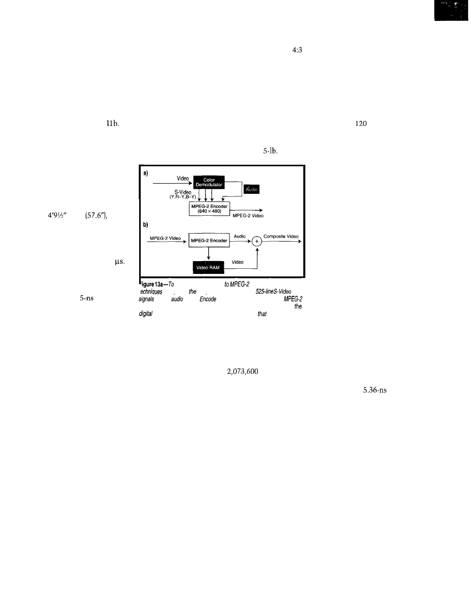
convert analog video
video, use conventional
to separate composite video into three
co/or
and an
signal.
the bottom 480 lines using the
encoder algorithm. b-To convert HDTV to analog NTSC video, store
image in memory and then convert a portion of
memory to a
video signal.
stray magnetic field deflecting the
electron beam 0.01” has the same effect.
Can someone build a TV that keeps
the horizontal sweep synchronized to
the intensity modulation to within 1 ns
and keeps the electron beam shielded
from magnetic and electrostatic fields?
Probably so.
Can anyone mass produce such a TV
at a price consumers will pay? I doubt it.
Will such a TV require constant ad-
justment? You bet your assets it will.
Front-projection TVs have a better
chance of achieving high definition
than CRTs. These systems have what
amounts to three separate B/W picture
tubes mounted in a single chassis.
One tube is driven by the red signal
and projected through a red lens onto a
movie screen on the wall. The other
tubes are driven by the green and blue
signals and projected through green and
blue lenses, respectively.
The CRTs can be smeared with a
continuous layer of phosphor (like an
coffee cans with three colored light
bulbs in each can.
To get full 1920 x 1080 resolution,
you’ll have to drink a lot of coffee
(5184 tons) to get the
cans
you need. If they start selling coffee
instead of beer at Dodger Stadium,
you’ll know why.
Such a screen could be made of
modules, each consisting of a matrix of
96 x 54 cells. They’d need 400 modules
to construct the entire screen. Each
module could have a micro taking color
information from a section of shared
memory and setting the brightness of
the 15,552 bulbs it’s responsible for.
Technically, there’s nothing to this.
But anytime you have over 6 million
light bulbs, you have to wonder, “How
many maintenance workers does it
take to change 6 million bulbs?”
Of course, there’s a higher-tech way
to build giant outdoor screens. Consider
a video wall of CRT screens. You may
have seen a TV news anchor standing
NEW MONITOR TECHNOLOGY
Home HDTV requires a break-
through in monitor technology. I
believe the solution requires
parallel processing. Here’s why.
Let’s go back to Figure 4,
which shows the response of a
phosphor dot to a single electron
beam pulse. To reduce flicker, the
electron beam must refresh each
phosphor dot before persistence
dies away, as shown in Figure 12.
Figure 12 isn’t drawn to scale because
doing so would be impossible. Earlier, I
said that for a 1920 x 1080 color picture
tube, the electron beam illuminates
the each phosphor dot for 5.36 ns every
33.3 ms [assuming a 30-Hz scan).
Suppose I drew the
pulse
0.01” wide. The pulses would be 5182
apart. Imagine the fold-out drawing!
The basic problem is that, regardless
of the frame rate, the duty cycle (the
ratio of illumination time to time
between illuminations) of the illumi-
nation pulse is O.OOOOl%! This is a
natural result of serial processing.
In a 1920 x 1080 color CRT, 6.22
million phosphor dots have to be illu-
minated one after another. Such volume
causes a serial processing bottleneck.
In computing, we solve this problem
via parallel processors.
Imagine a CRT with not one, not
three, but 1080 electron guns. Each gun
illuminates one line, so all 1080 lines
can be illuminated in parallel.
20
Issue
86 September 1997
Circuit Cellar INK@

Suppose you want to refresh the
screen not 30, but 300 times per second.
There are 5760 (1920 x 3) phosphor
bands per line. Each line is drawn every
3.33 ms, so each band is illuminated
for 578 ns every 3.33 ms for a duty
cycle of 0.017%.
I doubt it’s practical to build a CRT
with 1080 guns. But, maybe you could
build a linear array of tiny red, green,
and blue
If you put 5760
in a line and
multiplex the drive current to them,
you can produce a line of video. Then,
stacking 1080 of them would give you
a full 1920 x 1080 display with a
refresh rate.
If you receive
American video,
you just display each frame 10 times. If
you receive
European video, you
display each frame 12 times. Frame
rate becomes irrelevant.
I don’t expect anyone to build CRTs
with 1080 electron guns or displays
with 6 million
But, I do expect
someone to develop a flat-panel dis-
play (perhaps using liquid crystals,
phosphors deposited on silicon, or
another technology) that’s driven by a
large array of simple processors which
scan a section of video RAM and illu-
minate small portions of the screen in
parallel.
BUILDING CONVERTERS
Figure 13a shows a general approach
for converting analog video to SDTV.
The ATSC (Advanced Television
Systems Committee) Digital Televi-
sion Standard defines several data
formats. One is 640 x 480 at 29.97 Hz,
interlaced, which has a
aspect
ratio. It was clearly designed for encod-
ing the current American standard
analog video.
Remember, the first several lines of
analog video contain reference
signals for diagnostic and automatic
calibration purposes, so they don’t
need encoding.
You can use them to adjust the
gains of your color circuits, but other-
wise, they can be ignored. Use 480 of
the lines below the calibration signals
when encoding the picture.
Converting digital TV to analog is a
bit trickier. Digital TV signals may be
640 x 480 SDTV, 1920 x 1080 HDTV,
or the somewhat less popular 1280
x
720 and 704 x 480 formats.
You need an intelligent decoder to
figure out which format is being trans-
mitted. Once you’ve done that, you can
store the frame as an array in memory.
Then, you need to process some (or all)
of the data in this array and write it to
a video RAM that produces
analog video, as shown in Figure
When converting
HDTV
to
analog TV, you must decide
if you want to simply discard every
other line or average two adjacent lines
together. (I suspect the former is the
better choice.) You also need to decide
if you want to throw away the right
and left sides of the picture or shrink
the picture and add black lines at the
top and bottom.
MORE TECHNICAL INFO
Although this discussion barely
scratches the surface, I hope you’re
now more familiar with the problems
that need to be solved as well as the
background material which the more
advanced technical references assume
you already know.
If you want to do some research on
your own, start looking on the Inter-
net. The HDTV standard adopted by
the FCC is the one proposed by the
Advanced Television Systems Com-
mittee
home page is a good place to
get information on the MPEG-2 algo-
rithm. This algorithm is at the heart of
HDTV, and I really skimmed over it. It
deserves a whole article all by itself.
DVD looks like a good candidate for
recording digital television programs
and movies. Work your way down the
MPEG home page for a really good
FAQ page.
Of course, lots of manufacturers
have Web pages that bury useful infor-
mation in with their sales pitches. Use
your favorite search engine to look for
ATSC, MPEG-2, DVD, or HDTV.
The sci.engr.television.advanced
news group has an excellent informa-
tion/flame ratio. Post specific questions,
and you’re sure to get good responses.
HOW WE GOT HERE
Our TV broadcast system is a legacy
of
technology.
Frame rates are tied to the
line frequency and the persistency of
phosphor. The picture area is driven by
the compromise of fitting a rectangle
in a circle. Every advance had to be
backward-compatible with a 1950 TV.
Breaking tradition is hard. Back-
ward compatibility is good, but there
comes a time when you have to switch
from DOS to Windows. It’s painful at
first, but once you make the change,
you’re free to do much more.
With HDTV, pictures will be clearer
and screens larger. You can have
channel surround sound in your living
room. Eventually, you’ll be able to
choose among different languages for
some programs.
You will be able to store (and mani-
pulate) the images in your computer.
You can have
picture-in-picture, so you can watch
all the games (or soaps) at the same
time. You can even watch TV while
surfing the Internet. It is hard to imag-
ine all the possibilities.
It’s an exciting time to be working
(for fun or profit) in the television or
computer industry.
q
Do-While /ones has been employed in
the defense industry since 1971. He
has published more than 50 articles in
a variety of popular computer maga-
zines and has authored the book Ada
in Action. You may reach him at
A.G. Williams, Motorola general
sales manager, quoted in “40
Years Ago in Electronic Design,”
Electronic Design,
64, 1997.
ATSC, ATSC Digital Television
Standard, Document A53,
September 16, 1995.
Internet
DVD
MPEG/dvd.html#dvd-intro
sci.engr.television.advanced
401
Useful
402 Moderately Useful
403 Not Useful
Circuit Cellar INK@
Issue 66 September 1997
2 1
Mike Podanoffsky
Compressing Audio and
Video Over the Internet
uring the past
year, I’ve been part
of a team at
developing
3.0,
an Internet/Intranet
ing system. As I’m sure you know, the
Internet is a set of protocols (e.g., sock-
ets, HTTP, ftp, news, gopher, and POP3
mail) that runs on top of basic
Video conferencing over
is
based on the ITU H.323 standard. Other
standards exist for video conferencing
over ISDN (H.320) and POTS (H.324).
If you’re in the market for H.323
products, there are other options. Micro-
soft is giving
2.0 away free
as part of its Internet Explorer 4.0
suite, and Intel is pushing
Or, you could check out White Pine
Software’s popular Enhanced
Me system. All of these products re-
quire at least 32 MB of RAM and a
Pentium processor for effective use.
With
modems, it’s diffi-
cult to achieve anything greater than 3
frames per second (fps) for gray images
with little or no audio. You can appre-
ciate this relatively low quality of
service when you compare it to a 24-fps
rate of motion pictures in the U.S. or
to broadcast TV, which transmits color
images at 30 fps in the U.S. and Japan
and 25 fps in Europe.
For business-quality communica-
tions, you need 15-20 fps. This rate is
difficult to sustain over typical and
T3 Internet connections using
only video-conferencing systems.
PictureTel overcomes these limita-
tions by using a hardware/software
codec. This provides higher perfor-
mance, including audio-CD sound, full
color, and CIF [high quality) image size.
The codec is the heart of video
conferencing. It’s the component that
compresses and decompresses video
and audio datastreams.
The compression scheme is set by
international standards and recom-
mendations. Under H.323, the H.261
and H.263 proposal/standards define
video codecs; G.711, G.721, G.722,
G.723, G.728, and G.729 handle audio
and H.245 defines how a call is
established and capabilities exchanged.
Some of these protocols are also
part of the ISDN and POTS standards,
making it possible to communicate
packets of data between different types
of systems.
VIDEO COMPRESSION
H.261 video compression is essen-
tially MPEG compression. This lossy
compression scheme allows some
information to be lost in order to gain
substantial compression ratios (on the
order of
to
Visible quality
loss can be perceived at the higher
compression ratios.
Under H.261 and H.263, there are
two basic image sizes-CIF or QCIF.
CIF (Common Intermediate Format]
defines an image of 352 x 288 pixels,
roughly 4” x or one-quarter of an
800 x 600 screen. QCIF is 176 x 144
pixels, which is about one-quarter the
size of a CIF image (-2” x 2”).
Undersampling of color data is
possible without perceptible loss be-
cause the human eye is far more sensi-
tive to changes in brightness than
color. Color frames are actually only
176 x 144 for CIF and 88 x 72 for QCIF.
In other words, only a quarter of the
color data is ever sampled, stored, or
transmitted.
MPEG exploits motion detection as
part of its compression algorithm.
That is, successive frames in a
stream need only send and detect dif-
ferences. Each transmitted frame,
whether it’s a full or fractional part of
22
Issue
86 September 1997
Circuit Cellar INK@
an image, is encoded using
= 10.299 0.587 0.1141
Discrete Cosine Transform (DCT)
= -0.299 -0.587 0.8861
compression.
= 0.701 -0.587 0.1141
The value in each MPEG frame is
encoded using YUV-the same color
representation system employed by
video cameras. This system represents
the value of luminance (brightness) as
Y, followed by the blue and red
chrominance. Green can be derived
from these values.
(Do-While Jones offers slightly different
versions of these equations in
The New Digital Direction,” pp
Blue chrominance is always repre-
sented as the value of blue color minus
the luminance value. Similarly, red
chrominance is always represented as
the value of red minus luminance.
This color coding technique creates
values that can be converted to tradi-
tional RGB values via:
MPEG frames are divided into
x
16-pixel macroblocks. Each macroblock
consists of four 8 x 8 luminance blocks
and two 8 x 8 chrominance blocks-one
for blue and one for red chrominance.
Each block is compressed using
DCT. Macroblocks are created only if
they represent a difference in motion.
Frames can be encoded in three
types: intra-frames (I-frames), forward
predicted frames (P-frames), and bidi-
rectional predicted frames (B-frames).
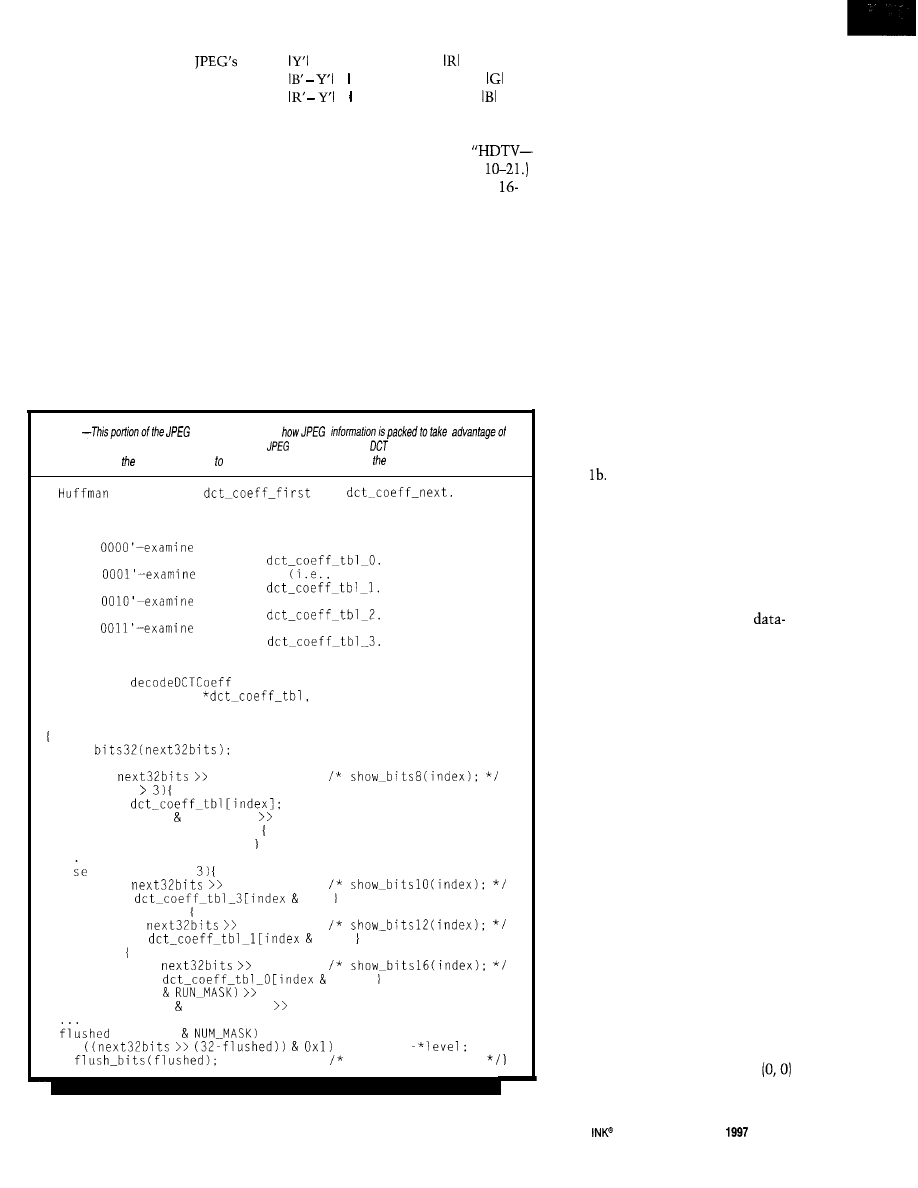
Listing1
decodershows
every bit. Four fables exist at the beginning of every
file to store the actual
coefficients. The
remainder of frame uses offsets these values, which further reduces size of every image.
*
Decoder for
and
It
* examines the next 8 bits of the input stream and performs the
* following cases:
*
* '0000
8 more bits (i.e., 16 bits total) and perform
*
table lookup on
* '0000
4 more bits
12 bits total) and perform
*
table lookup on
* '0000
2 more bits (i.e., 10 bits total) and perform
*
table lookup on
* '0000
2 more bits (i.e., 10 bits total) and perform
*
table lookup on
* Each time, one more bit is examined to determine sign of level.
static void
(unsigned short int
unsigned
int *run,
int *level)
show
flushed = 0;
index =
24;
if (index
value =
*run = (value RUN-MASK) RUN-SHIFT;
if (*run == END OF BLOCK)
*level = END-OF-BLOCK;
if (index ==
index =
22;
value =
31;
else if (index)
index =
20:
value =
151:
else
index =
16;
value =
2551;
*run = (value
RUN-SHIFT:
*level = (value LEVEL-MASK) LEVEL-SHIFT:
= (value
+ 2;
if
*level =
Update bitstream;
An MPEG image always begins with
an I-frame. These I-frames are inserted
at regular intervals in the stream, usu-
ally every 400 ms.
This timing is crucial for synchroni-
zation. For instance, should the stream
only contain differences, once some
data becomes lost or corrupted, the
remainder of the video is useless.
I-frames are encoded as a single
image with no reference to past or
future frames. The encoding scheme is
similar to JPEG compression.
Each 8 x 8 block is encoded inde-
pendently, and its values are trans-
formed using a DCT, which separates
the image into independent frequency
bands. The resulting data is quantized
and run-length encoded in a zigzag
pattern, as shown in Figure 1.
If you take an image as shown in
Table la, the coefficients produced by
the DCT logic produce the result in
Table Notice the unique zigzag
pattern produced by the algorithm.
Quantization is the lossy part of
JPEG compression. It reduces the size
of the resulting data by removing the
difference between like values.
So, if an image contains ten hues of
red, they are reduced to three (or fewer).
How much is removed from the
stream dictates how much compression
is achieved.
A P-frame-or, forward-predicting
frame-is encoded relative to the past
reference frame, which is the closest
preceding reference frame. It can be
either a P- or an I-frame.
Each macroblock in a P-frame can
be encoded as an I- or P-macroblock.
An I-macroblock is encoded just like
one in an I-frame. But, a P-macroblock
is encoded as a 16 x 16 area of the past
reference frame plus an error term.
To specify the 16 x 16 area of the
reference frame, a motion vector is
included. A motion vector (0, 0) means
the 16 x 16 area is in the same position
as the macroblock being encoded. Other
motion vectors are relative to that posi-
tion and may include half-pixel values,
in which case, pixels are averaged.
The error term is encoded using the
DCT, quantization, and run-length
encoding. A macroblock may also be
skipped, which is equivalent to a
vector and an all-zero error term.
Circuit Cellar
Issue 86 September
23
2 5 0 0 A D
SYSTEMS@, INC.
120 Union Street
l
PO. Box 490
Rockport, Maine 04856 USA
(800)
448-8500
(207) 236-9055
2 4
Issue 86 September 1997
The search for a good motion vector
(i.e., one giving a small error term and
good compression) is the heart of any
MPEG video encoder. It’s also the
primary reason why encoders are slow.
A B-frame can be encoded relative
to the past reference frame, the future
reference frame, or both. The future
reference frame is the closest following
reference frame (I or P).
Encoding for B-frames is similar to
P-frames, except motion vectors may
refer to areas in the future reference
frames. For macroblocks using both
past and future reference frames, the
two
16 x 16
areas are averaged.
Frames don’t have to follow a static
IPB pattern. Each individual frame can
be of any type. For simplicity, however,
a fixed IPB sequence is often used
throughout the entire videostream.
Frames can also be sequenced in an
IBBP BBP order. In this case, the B
frames may depend on information in
future P-frames, which is why they’re
referred to as future frames.
The
may have two frames in
memory-I and P-and may be send-
ing B-frames that appear to the receiver
to be referencing future frames. In
other words, the sender may have sent
frames in the order IBBP BBP BBP, but
the receiver must process them in the
order IPBB PBB PBB.
Obviously, B-frames aren’t much
good until the future frame arrives, but
the transmission channel is used as
soon as the information is available.
Dead channel time gets wasted.
Since the encoding is figured out,
let’s try decoding. This article’s source
code includes MPEG and audiostream
decoders, located in Vi
zi
p.
The MPEG code is taken from
Listing
in
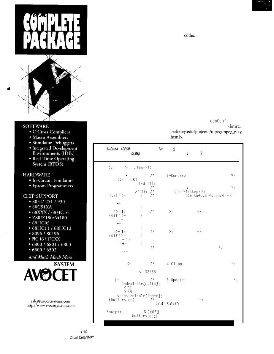
encoding (taken from a ud a dcpm.
is represented as specific offset
values from a base
value. Those values are taken from the n dex Tab
e
array shown in step 5.
The previous steps determine whether a new step is required.
for len 0
val = *inp++:
diff = val valpred;
Step
with previous value
sign =
? 8 : 0;
if (sign) diff =
delta = 0;
vpdiff = (step
Step Z-Divide *approx* computes:
delta =
if
step)
delta = 4:
and vpdiff =
diff step;
vpdiff += step;
step
shift step by 1
if
step)
delta 2:
diff step;
vpdiff += step;
step
shift step by 1
if
step)
delta
vpdiff step;
if (sign)
Step 3-Update previous value
valpred
vpdiff;
else
valpred += vpdiff;
if (valpred 32767)
Step
prev value to 16 bits
valpred = 32767;
else if (valpred
valpred = -32768;
delta sign;
Step
index and step values
index +=
if (index index = 0;
if (index
index = 88;
step =
if
Step 6-Output value
outputbuffer = (delta
else
= (delta
outputbuffer;
bufferstep =
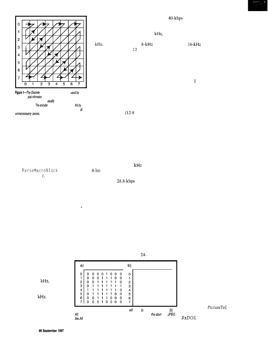
Cosine Transform
JPEG
converts
into coefficients in cosine
functions. These values are
distributed in
a zig-
zag pattern.
takes
advantageof
ordering the coefficientsin this pattern to eliminate
The code is thorough, fairly well
documented, and very useful in ana-
lyzing MPEG streams. It’s written for
Unix and X/Windows and has not been
ported to Windows, but it should run
under Linux. (I didn’t write this code,
so please don’t call me with problems.)
The MPEG macroblock decoder,
where everything starts, is handled by
the
functionin
mpeg\vi deo.
It decodes macroblocks
and reconstructs motion vectors, which
in turn leads to reconstructing DCT
values and setting pixel values.
The code that decodes the DCT
values from the input stream is more
interesting. It is handled by decode
DCTCoeffinmpeg\decoders.c.
Listing 1 shows a portion of this code.
As you can see, an MPEG image has
lots of control information and mani-
pulation of bits. Bandwidth shouldn’t be
wasted, even at the expense of com-
puter time.
AUDIO COMPRESSION
The human ear is much
more sensitive than the human
eye. Hearing can typically
perceive frequencies between
20 Hz and 20
with the
human voice capable of pro-
ducing frequencies between
40 Hz and 4
For desktop
video-conferencing systems,
the challenge is reproducing
the highest fidelity of sound in
real time.
To faithfully reproduce a signal, it
must be sampled at twice the highest
frequency. The high-quality audio of
audio CDs is sampled at nearly 44
while the telephone samples voice at
8
Encoding the entire
range requires at least bits of data.
To achieve compression, 256 values
are selected that can be encoded in
8 bits. Since human voice is concen-
trated at the lower frequencies, the
algorithm uses a logarithmic scale to
determine which frequencies to code.
Each value in the raw analog input is
mapped to the closest lower frequency
in a technique called Pulse Code Modu-
lation (PCM).
G.711
uses this technique
to encode audio and achieves a 1.5: 1
compression ratio
bits).
Two different logarithmic curves
are used as standards-u-law and a-law.
u-law is used in North America and
Japan, while a-law is used elsewhere.
Neither one really has a technical
advantage over the other. They repro-
duce audio slightly differently, and any
preferences between them tend to be
based primarily on personal taste.
A sampling rate of 8
encoded as
data using a single mono channel
requires a bandwidth of 64 kbps-much
higher than a
modem can
sustain. Some compression is necessary.
Experience shows that adjacent
values in an audiostream can be simi-
lar to each other. Moreover, a sample’s
value can be predicted with some ac-
curacy using the value of adjacent
samples.
ADPCM (Adaptive Differential Pulse
Code Modulation) encodes the differ-
ences between the predicted and actual
values of a sample. In G.721, these
differences are encoded as 4-bit values,
requiring only 32 kbps. G.723 uses the
same technique to provide
and
0 123456 7
audiostreams. These all use 3
and 5 bits for encoding audiostreams.
G.722, developed by AT&T in the
U.S. and CNET in France, is another
standard using ADPCM. It samples data
at a higher
rate and then divides
this data into two channels-one for
higher and one for lower frequencies.
It uses 8 bits to encode differences.
The output is Huffmanized (run-length
encoded) and can be transmitted on
one or two channels simultaneously,
providing a 4: compression ratio.
Audio compression is a little more
readable, so let’s take a look. This
example is similar to that used in G.721
and is also easier. Listing 2 is part of
audio\adcpm.cfromVideoConf.zip.
ADPCM is encoded by taking the
difference between the current and
previous values. The difference value
may be too large to encode in 4 bits, so
a step value is adopted, which forms
the basis for future values.
When a call is placed, it’s unlikely
that both systems will have the same
capabilities. Given the likelihood of
mismatched systems, using the H.245
standard is probably best. It recognizes
and negotiates the best-quality audio
and video possible.
When two systems connect under
H.245, they select a random wait time.
One system wins and drives the process
of finding the best quality of service
based on an exchange of capabilities.
That process starts by transmitting
a set of options supported, ordered
with the preferred services. The receiver
responds with the services it can accept.
Obviously, no conferencing results if
the systems cannot agree on common
formats.
SEE YOU SOON?
0 1 2 3 4 5 6 7
Now that video conferencing is for
real on TCP/IP and Internet
connections are reaching the
1 -Mb range with ADSL, there’ll
be lots of growth with this type
of service.
4 o - 2 0 0 0 0 0
0 - 1 0 1 0 0 0 0
- 2 0 0 0 1 0 0 0
0 1 0 0 0 - 1 0 0
0 0 1 0 0 0 0 0
0 0 0 - 1 0 0 0 1
0 0 0 0 0 0 0 0
0 0 0 0 0 1 0 1
See you soon.
q
Table 1 -A simple pixel image (a) convert the coefficients shown in
coefficients are stored in one of several fables located at
of a
references to values in frames are represented as offsets in these fables.
Mike Podanoffsky is an inde-
pendent software engineer who
has worked at
Lotus,
and Sybase. He authored
a DOS clone, and is
26
Issue
Circuit Cellar INK@

now working on a
Virtual Ma-
chine for embedded systems
You
may reach Mike at
corn.
Source code for this article can be
found on the Circuit Cellar Web
site and at
www.tbi.net/-jhall/voice/digitize.htm
code.html
3.0
Corp.
100 Minuteman Rd.
Andover, MA 01810
(508) 292-3500
Fax: (508) 292-3327
info@pictel.com
www.picturetel.com
Enhanced CU-See-Me
White Pine Software
542 Amherst St.
Nashua, NH 03063
(603) 886-9050
Fax: (603) 886-9051
www.cu-seeme.com
Intel Corp.
5000 West Chandler Blvd.
Chandler, AZ 85226-3699
(602) 554-8080
Fax: (602) 554-7436
www.intel.com
2.0
Microsoft Corp.
One Microsoft Way
Redmond, WA 98052
(206) 882-8080
Fax: (206) 936-7329
404
Very Useful
405 Moderately Useful
406 Not Useful
a
simple formula.
Buy a
from
Grammar Engine and
you’ll save money 3 ways.
First,
is amazingly
affordable,
at just $495.
to save you money
Then, you can
re-use
it works with any micro,
allowing you to avoid
cost custom tools. Finally,
there is the investment
you’ve made in a tool that
is easily upgradeable as
your needs change. Call
us today and try
FREE for 30 days. It may
just be the best investment
you can make in firmware
development tools.
Grammar Engine Inc.
Dr., Suite 122
OH 43081
Phone
l
Fax
l
Sales
l
Web:
Circuit Cellar
Issue 86 September 1997
2 7
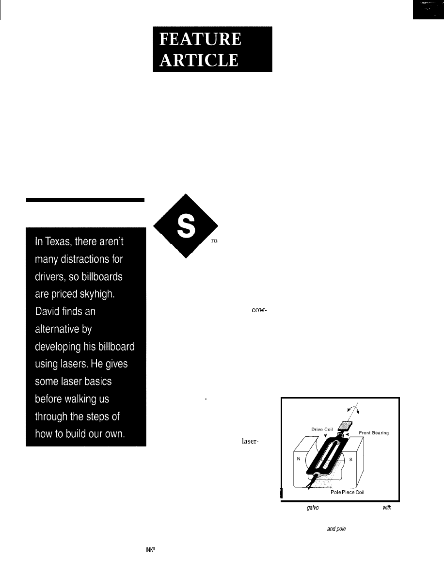
The Laser
Billboard
David Prutchi
A Low-Cost Laser
System
Image Projection
outheast Texas
roads are long and
desolate. Driving for a
few hours is so boring, we
often find ourselves naming the cows.
“Hey, honey!” I’m often reminded,
“Better not get too attached. Betsy there
might end up as dinner some night.”
Considering that only the infrequent
sight of a bobbing oil pump tops
naming as a distraction, it’s no surprise
that roadside billboards in this area are
so effective. Yet, when my wife recently
tried leasing one to advertise a new
hotel, they were next to impossible to
find and ridiculously expensive.
It was time to bring high tech to the
rescue. Let’s see, where did I put my
laser? We’ll also need a large barn wall
facing the road..
LASER PROJECTOR
Unlike the electron-beam raster
scanning method that reproduces TV
images on the face of a CRT,
graphics projectors usually employ
vector scanning. The laser beam is
steered along the contour to be drawn
to form a cartoon-like picture.
Vector scanning happens at the heart
of a laser projector through the scanner
assembly. Inside, two electromechanical
galvanometers (“galvos”) move small
mirrors that steer the laser beam under
computer control.
A galvo resembles a small DC motor
with a restricted range of rotation (see
Figure
1).
A current flowing through
the drive coil induces a magnetic field
that interacts with the constant mag-
netic field of the pole-piece coil.
Torque created by the magnetic
interaction causes the rotation of a
small mirror affixed to the shaft of the
galvo’s moving armature. An imping-
ing laser beam is then deflected along a
line perpendicular to the mirror’s axis
of rotation. The laser dot’s position on
the image line depends on the current
flowing through the drive coil.
Two galvos mounted orthogonally
with respect to each other can position
the laser dot anywhere on a 2D image
plane. Scanning this dot at high speed
forms the cartoon-like image.
In a CRT, a complete image is fully
available for a brief instant because
phosphor on the screen keeps glowing
after the electron beam crosses over it.
But, laser-graphics image formation
can’t rely on the persistence of the
projection screen. It relies solely on
the limited temporal response of the
human visual system. So, the projected
image’s quality depends highly on the
speed with which the beam can be
steered and retraced.
Unfortunately, the electromechani-
cal deflection mechanism in a laser
projector has a high inertia compared
to the electromagnetic or electrostatic
deflection used in CRTs. Inertia and
other dynamic parameters make it
increasingly difficult to accurately
position a laser beam on the image
plane as high-frequency components
are introduced in the control signals.
Mirror
Pole Piece
Figure 1 -A
resembles a small DC motor
a
very restricted range of rotation. The mirror affixed to
the armature moves via magnetic repulsion or attraction
between the drive coil
piece.
28
Issue 86 September 1997
Circuit Cellar
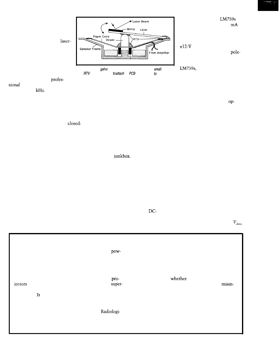
Under these conditions, a laser
projector’s bandwidth is typically
limited by the first uncontrolled
mechanical resonance of the
galvos. As a rule of thumb,
dot positioning as a function of
drive current is repeatable only if
the drive signal is bandwidth
limited to below one-fifth of the
first resonant frequency.
Figure 2-A crude
can be built from a speaker and a
mirror.
Voice Coil
Despite efficient design and
lightweight mirrors, a
Use
silicon adhesive
the
material lever the speaker
casing and to ho/d a wooden dowel between the paper cone and lever.
op-amps. The pair of
in
Figure 3 provide up to 325
of
drive current to each galvo.
The amplifiers are operated at
unity gain from symmetrical
power supplies. A sepa-
rate +12-V line powers the
piece coil.
It’s difficult to damage the
given their internal
current limiting and thermal
shutdown. However, they do run
system’s first resonance usually
appears at
1-5
It’s difficult to
retrace a complex image slow enough
not to generate drive components be-
yond a few hundred Hertz, yet fast
enough for retinal image formation
with minimal flicker.
High-end projectors employ
loop control to extend the system’s
useful bandwidth. Galvos with integral
position sensors are used within a
servo control loop.
Performance doesn’t come cheap.
Professional-grade galvos run at about
$500-800 per axis. (Recall that two are
required for 2D scanning.)
An affordable alternative that will
get your feet wet in laser graphics is a
$75 two-axis open-loop scanner sold by
Meredith Instruments (see Photo 1).
With a first resonance at -200 Hz,
its performance cannot be remotely
compared to its more expensive-coun-
terparts’. Still, it can be used as the
basis for a laser-graphics system capable
of projecting simple vector graphics
and geometrical pattern animations.
There’s one more alternative to com-
puter-controlled laser graphics on a
shoestring. As Figure 2 shows, you can
build a crude galvo from a small speaker
(e.g., 1 W) and lightweight mirror.
Construct the lever from a piece of
PCB or prototyping board. Carefully
glue a small wooden dowel to the center
of the speaker’s paper cone. Use RTV
silicon adhesive to form the fulcrum
and link the dowel tip to the lever.
For the two orthogonal galvos needed
for 2D projection, you may find all the
parts in your
But, due to this
arrangement’s extremely poor frequency
response, don’t expect to reproduce
more than the crudest graphics and
geometrical patterns.
GALVO AMPLIFIERS
The pole magnetic field in a galvo is
usually established by energizing a coil
with a DC current. The drive coil, on
the other hand, is powered by a
coupled amplifier.
Driving a small open-loop servo is
simple with widely available power
hot, so ample heat sinking is necessary.
Although galvo-amplifier design may
look relatively straightforward using
any suitable commercial power
amp, a more complex design is needed
once you decide to upgrade to profes-
sional-grade galvos. Driving the higher
power units can be particularly chal-
lenging since they present a reactive
load as well as reverse electromotive
force (EMF) to the driving amplifier’s
output stage.
This EMF is generated when the
drive signal works against the galvo’s
inductance and inertia, and it must be
considered in the driver’s design. In
general, DC coupling into inductive
loads is problematic because the cur-
rent waveform lags the applied drive
voltage, resulting in higher instanta-
neous and average power dissipation.
Interestingly, however, the same
reverse EMF can be fed back to the
driving amplifier to dampen unwanted
oscillations and extend the usable galvo
bandwidth. The coil drive voltage
for a certain galvo may be expressed by:
Laser Safety
Even low-powered laser beams may cause irreversible
must be taken by the designer and builder to ensure proper
damage if aimed directly at the human eye. Higher
handling, construction, and labeling of these supplies.
ered beams can start fires, burn flesh, ignite combustible
This laser-projector project is presented exclusively
materials, and cause permanent eye damage from even
for informational purposes. The author does not make
scattered reflections.
representations as to the completeness or accuracy of the
Therefore, a laser beam or its reflections should never
information contained herein and disclaims any liability
be aimed at yourself or anyone else. Lasers and laser
for damages or injury,
caused by or arising from
should be used only by adults or with adult
lack of completeness, inaccuracy of information,
vision. Although used for entertainment, a laser projector
terpretation of directions, misapplication of circuits and
is not a toy. must be used safely and responsibly.
information, or otherwise.
Laser projectors and laser light shows are regulated by
the federal government in addition to many state and
CDRH-Food and Drug Administration
local authorities. The Center for Devices and
U.S. Dept. of Health and Human Services
cal Health (CDRH) handles certification.
1390 Piccard Dr., HFZ-312
Laser projects often involve power supplies capable of
Rockville, MD 20850
producing severe electrical shock. Proper safety precautions
(301) 427-l 172
Circuit Cellar INK@
Issue 86 September 1997
29
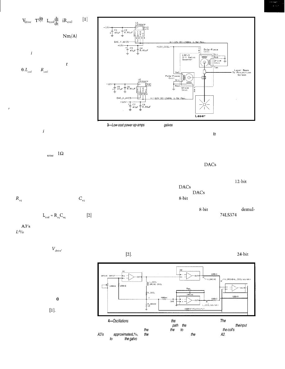
=
+
+
dt
where T is the torque constant, a galvo
parameter (expressed in
that
describes how much torque is produced
on the rotor assembly by each ampere of
current flowing through the drive coil.
The absolute angular position of the
rotor assembly at any time is expressed
by
and
are the inductance and
resistance of the drive coil, respectively.
Considering that the torque should
ultimately equal the inertial resistance
of the rotor and mirror, oscillations
may be dampened by tailoring the
system’s transfer function as shown in
Figure 4. Here, I included the measur-
able terms of equation
1
within the
output amplifier’s feedback path.
The instantaneous current through
the drive coil is converted to a corre-
sponding voltage signal by the current
sense resistor:
R
=
The resistors and capacitors on the
input and feedback paths of A3 differ-
entiate this signal and simulate the
effect of such current variation on an
RC equivalent of the coil’s inductance.
To do so, the equivalent resistance
and the equivalent capacitor
are
chosen such that:
output approximates the term
of equation
1.
At the same time,
the instantaneous voltage across the
coil is sampled by op-amp A2, providing
a measurement of
Extending this control concept,
closed-loop galvos have an integral
position sensor to provide position
feedback signals to a servo amplifier.
It’s easy to understand, then, that servo
amplifiers for closed-loop scanning
take full advantage of equation
1
by
providing an actual measurement of
the angular position to a suitable
transfer function relating position to
the drive current
Due to their low inertia, capacitive
sensors have been the most popular
position detectors in closed-loop galvos.
The servo controller is typically imple-
mented by an analog circuit that places
Figure
can drive the
of the two-axis scanner. Currents f/owing through the drive
coils induce magnetic fields that interact with the constant magnetic field generated by the pole-piece coil in each galvo.
The laser beam is deflected in each axis proportionately to the drive voltage applied the respective power op-amp.
the position sensor within the ampli-
fier’s feedback path.
In general, the servo system is de-
signed with a bandwidth broad enough
to reject dynamic disturbances to the
galvo’s position, such that the scanner’s
output closely reproduces the control
input signal.
As well, notch filters at the galvo’s
resonances are often used on the control
signal input path. This technique makes
it possible to extend the servo’s con-
trol bandwidth by skipping over prob-
lematic phase crossover frequencies.
A discussion on the theoretical
background required for designing
closed-loop control circuits is beyond
the scope of this article, but you
should have no problem finding good
references with varying degrees of
sophistication
PROJECTOR CONTROL
low-cost laser projector requires play-
ing the image’s vector coordinates
Driving the galvo amplifiers of the
through two
into the amplifier
inputs. The circuit of Figure 5 enables
the PC to drive two Analog Devices
AD667 (or Maxim MAX667)
from the parallel printer port.
The
receive data from three
latches. The printer port presents
the required 24 bits of data as three
sequential
words which are
tiplexed by the three
latches.
U4 holds the four least significant
bits of each DAC. U3 holds the 8 most
significant bits of the x-channel DAC,
while U5 holds those of the y-channel
DAC.
If desired, S-bit operation can be
selected through J2. Once the
Figure
may be dampened by tailoring galvo system’s transfer function.
measurable terms of
transfer function can be included within the feedback
of output amplifier. The components on
and
feedback paths of A3 differentiate
current through
coil simulate current variation on
inductance.
output
and instantaneous voltage across coil is sampled by
These signals
combine dampen
at critical operafing points.
30
Issue
86 September 1997
Circuit Cellar INK@
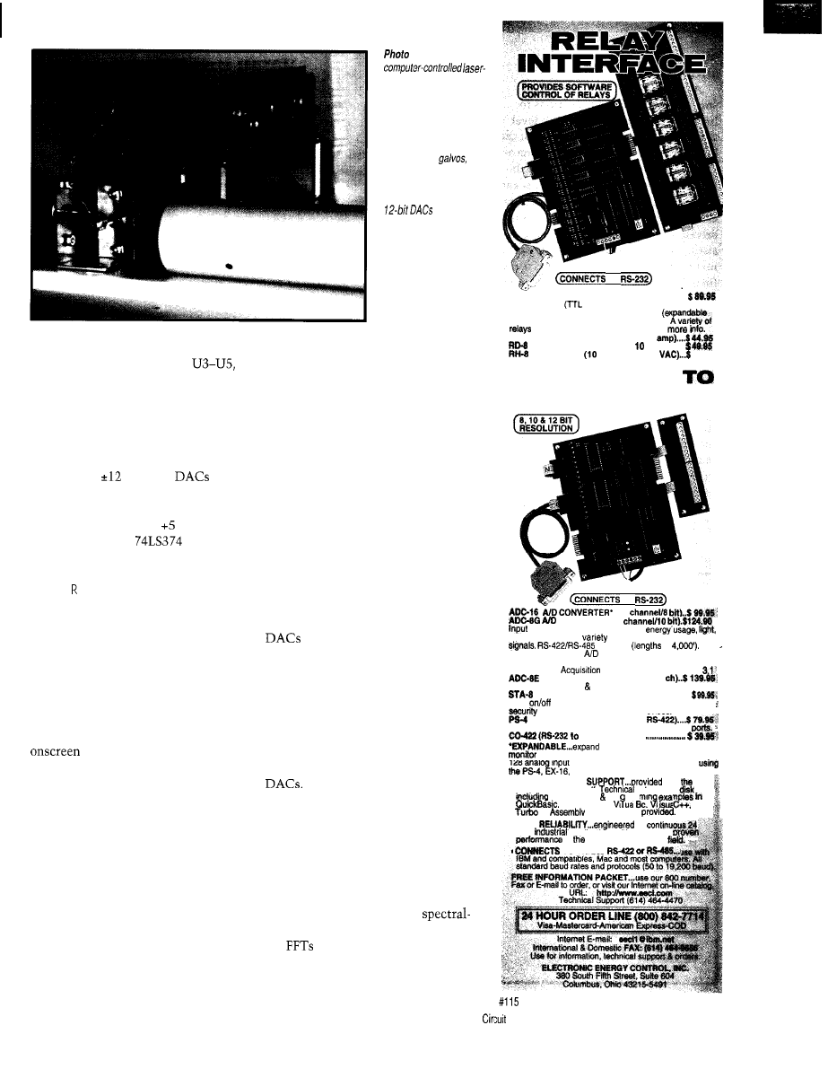
information defining a coordinate pair
i s a v a i l a b l e a t t h e o u t p u t s o f
the DAC outputs are simultaneously
updated by strobing pin 16 of the
printer port.
Power is obtained from the circuit
shown in Figure 6. Current from a 1-A
12-VAC transformer is rectified and
regulated to
V for the
and
galvo amplifiers. A separate +12-V
regulator powers the pole-piece coils of
the galvos. In addition, V is gener-
ated to supply the
latches.
USING VECTOR GRAPHICS
LAS E . BA S,
a Quick BASIC program,
is used to draw vector graphics that can
then be displayed by the laser projector.
The vector-graphics drawing tablet is
controlled through the cursor-move-
ment keys (i.e., keyboard arrows or
numeric keypad).
The spacebar is used to toggle on
and off the line to be traced by the laser.
Coordinates of points that appear red
are stored in a vector-image
file, while green points are disregarded.
To draw a figure, take the cursor to
the desired initial point using a green
line [tracing off) and toggle on the
saving of coordinates (red tracing).
Draw the image point by point, turn-
ing the tracing off as necessary.
Keep in mind, however, that this
laser projector has no retrace blanking.
As such, a line is generated between
successively traced segments.
You’ll soon notice it’s not easy to
draw just by attempting to trace over an
imaginary cartoon of the desired figure.
7-A simple
graphics projector can be
built around an inexpen-
sive two-axis open-loop
scanner. The fop circuit
board comprises the
power op-amps that drive
the scanner’s
as
well as the power-supply
components. The lower
circuit board has two
and an
inferface connecting to
the PC printer port
TO
It’s much easier to first draw the figure
on a transparent film (e.g., the trans-
parencies used for overhead projection),
overlay it on the computer screen, and
trace the figure with the cursor keys.
By keeping the flow of the figure as
smooth as possible, with generous
curves and few discontinuities, you
will band limit the drive signals and
hopefully not excite undesirable reso-
nances. If you plan to project letters or
words, use smooth cursive writing and
add an artistic return path for the re-
trace beam connecting the first and
last points.
Projection is accomplished by writing
the stored coordinates in an endless
loop. Since the writing speed to the
is highly dependent on system
factors (e.g., CPU clock speed, OS shell,
and Quick BASIC compiler version),
you’ll need to tweak the program’s
operation to achieve proper results.
The program includes code to skip
over unnecessary coordinate points, as
well as introduce delay loops between
successive write operations to the
In general, keep the writing
speed sufficiently low to obtain good
beam steering, yet high enough to
generate a flicker-free image.
This software is intended only as an
example of implementing an open-loop
vector-graphics control program. Major
enhancements could be made to it.
First of all, an FFT-based
analysis routine (see “Spectral Analy-
sis:
and Beyond,” INK 52) could
help analyze the beam’s path and look
for frequency components which could
AR-16 RELAY INTERFACE (16 channel) . . . . . . . . . . . .
Two 8 channel
level) outputs are provided for
connection to relay cards or other devices
to 128 relays using EX-16 expansion cards).
cards and relays are stocked. Call for
AR-2 RELAY INTERFACE (2 relays, 10
REED RELAY CARD (8 relays,
VA) . . . . . .
RELAY CARD
amp SPDT, 277
66.66
A N A L O G
D I G I T A L
TO
(16
CONVERTER’ (8
voltage, amperage. pressure.
joysticks and a wide
of other types of analog
available
to
Call for info on other
configurations and 12 bit
converters (terminal block and cable sold separately).
Includes Data
software for Windows 95 or
TEMPERATURE INTERFACE” (6
Includes term. block 8 temp. sensors (-40’ to 148’ F).
DIGITAL INTERFACE* (6 channel) . . . . . . . . .
Input
status of relays, switches, HVAC equipment,
devices, keypads, and other devices.
PORT SELECTOR (4 channels
Converts an RS-232 port into 4 selectable RS422
RS-422 converter)
your interface to control and
up to 512 relays, up to 576 digital inputs. up to
128 anal
ST-32 8 AD-16 expansion cards.
inputs or up to 128 temperature inputs
l
FULL TECHNICAL
over
telephone by our staff.
reference 8
test software pro rammi
GW Basic,
C.
and others are
l
HIGH
for
hour
applications with 10 years of
in
energy management
.
TO RS.232,
Cellar INK@
Issue 86
September
1997
3 3
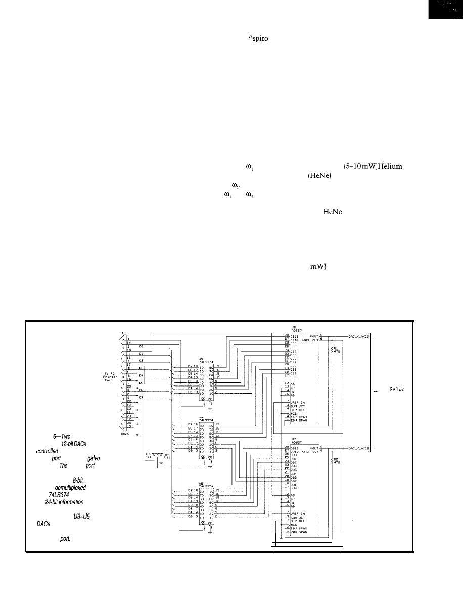
trigger unwanted resonances in the
galvos.
A suitable algorithm could then
smooth over the hard transitions to
limit their spectral content to a level
the galvos can handle. Or, the signal can
be notch filtered to skip over the reso-
nance frequencies to gain bandwidth.
Other interesting improvements can
be implemented through software. For
example, if a mechanical resonator is
driven with a stair-step function con-
sisting of an intermediate level approxi-
mately halfway between the initial and
final drive values with a duration equal
to half the period of the resonator,
overshoot and ringing are suppressed.
As such, the inertial load tends to
arrive to the final rest position at zero
velocity with a total time of one-half
the resonance period for the move.
You may also add a more powerful
graphics editor that enables freehand
drawing using a mouse or light pen,
fancy graphic and animation routines,
and a nice Windows-based GUI. If you
write such software, please share it
with the rest of us.
ANIMATED GEOMETRIC PATTERNS
It’s not always necessary to manually
enter a figure for display. Interesting
graphics can be synthesized using math-
ematical functions. Rotating
graph” patterns are easy to generate and
display using the laser projector.
These patterns are created by driving
the x- and y-axes with continuous sinu-
soidal signals of different frequency,
amplitude, and phase. Since the frequen-
cy content of these signals is limited
and no discontinuities exist in the sig-
nal or its derivatives, even rudimentary
galvos like those in Figure 2 can project
these patterns with good performance.
In LASER. BAS, Lissajous patterns
are generated by driving the x-axis galvo
with a sinusoidal frequency while
driving the y-axis with an quadrature
sinusoidal of frequency
The ratio between and deter-
mines the number of peaks in the
Lissajous pattern. Introduce rotation
by slightly increasing the phase differ-
ence between the signals each time a
complete pattern is traced.
Polar roses are generated by not only
feeding the x- and y-axis with quadra-
ture signals, but by also varying the
amplitude of the sinusoidal components
with another sinusoidal function. The
number of loops in the polar rose is
given by the frequency of this third
sinusoidal component.
Complexity can be taken one step
further by making the driving function
for each galvo contain various sinusoi-
dal components of varying phase and
amplitude. One result is to generate
collapsing spirals that give the illusion
of a rotating black hole.
Go ahead. Dig out your old trigo-
nometry and analytic geometry books
and keep on playing!
LASERS
Of course, an indispensable part of a
laser projector is the laser. And, almost
any visible kind can be used for display.
Low-powered
Neon
lasers are suitable for
indoor and limited exterior light shows.
They’re inexpensive-surplus units
can be found for as little as $35.
Typical
lasers produce red
light at 633 nm, but green (543 nm),
yellow (594 nm), and orange (612 nm)
ones are now available, albeit at higher
prices than their red counterparts. For
a few thousand dollars, high-power
(30-50
versions are also available
for serious light-show displays.
Another low-cost alternative is to
use a visible laser diode. Since it’s not
usually possible to effectively drive a
laser diode at room temperature from a
Figure
AD667 (or
MAX667)
are
from the parallel
printer
to drive the
amplifiers.
printer
presents 24 bits of data as
three sequential
words
that are
by
three
latches. Once
the
defining
a coordinate pair is available
at the outputs of
the
are simultaneously
updated by strobing pin 16 of
the printer
T o
Drivers
34
Issue 86 September 1997
Circuit Cellar INK@
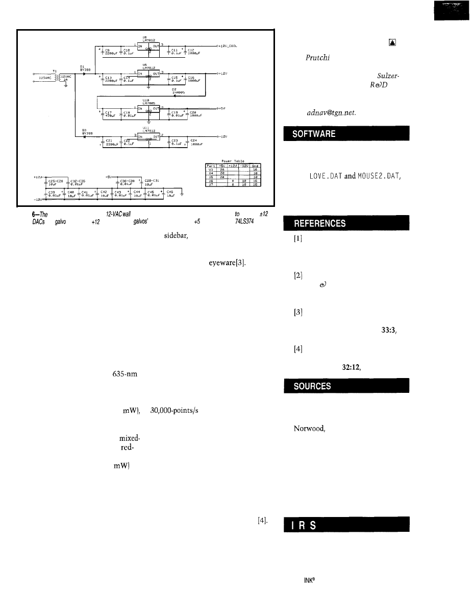
Figure
projector is powered by a
transformer. The circuit uses linear regulators produce
V
for the
and
amplifiers,
V to power the
pole-piece coils, and V to supply the
latches.
DC source, laser diodes are available
with a photodiode used for driving con-
trol. The photodiode yields a signal that
automatically controls the laser diode’s
power output as a function of the cur-
rent delivered by the driver circuit.
Diode lasers can also be found as part
of modules that include a diode, driver,
beam-collating optics, and case that
operates as a heat sink. Battery-operated
pencil-like laser modules are widely
sold as laser pointers.
In any case, these modules require
only a DC power source and typically
produce red beams at either 670 or
635 nm. If possible, select the
wavelength, since at the same power,
it’s four times brighter to the human
eye than the 670-nm wavelength. Be-
cause of their reduced power (3-5
however, diode lasers are suitable only
for indoor and studio work.
For outdoor graphics, argon or
gas argon/krypton (green-blue or
yellow-green-blue) do the best job.
Medium-power lasers (30-100
can handle most indoor graphics as
well as indoor beam effects.
Events in which beams must be
visible under adverse conditions (e.g.,
outdoor shows in high-brightness areas)
usually demand water-cooled lasers
with optical power outputs that often
reach 5 W!
Regardless of the laser you select,
please keep safety in mind at all times
(see
“Laser Safety”). Never aim
a laser beam or its reflections at your-
self or anyone else, and always use
appropriate safety
THE BIG PICTURE
Recently, a sports commentator on
NPR complained that today’s basketball
games are perceived as necessary distur-
bances in between the pregame and
intermission laser shows.
Despite his exaggeration, laser shows
seem to be everywhere these days-from
small tradeshow booths to the Olympic
Games. Their frequent use is mostly
due to the advanced technology that
has emerged in the last few years.
Galvo writing speeds in high-end
professional projectors are now in the
range, and acousto-optic
modulators can create full-color images
from “whitelight” laser sources. In
addition to the vector graphics that can
now be created, modern laser projectors
can display full-color raster graphics.
These images are not VGA-quality,
since the achieved resolution is only
about 50 pixels x 50 lines. But, through
image-processing magic, subtly shaded
photos can be scanned and projected in
a fraction of the time it takes an artist
to draw a vector-graphics cartoon
Well, using the laser to project an
ad on the old barn along the highway
might not be such a good idea after all.
But, I’m sure to make the other dads
jealous when my kid’s birthday party
is preceded by a cool laser-show.
David
has a Ph.D. in Biomedi-
cal Engineering from Tel-Aviv Univer-
sity. He is a staff engineer at
Intermedics, and his main
inter-
est is biomedical signal processing in
implantable devices. You may reach
him at
The LASER. BAS Quick BASIC source
code for this article can be found on
the Circuit Cellar Web site along
with
demo graphics for the project, and
SOURCES. TXT, additional sources
for laser equipment.
P. J. Brosens, “Scanning Speed
and Accuracy of Moving Magnet
Optical Scanners,” Optical Engi-
neering, 34, 200-207, 1995.
F.P. Tedeschi, How to Design,
Build, Use Electronic Control
Systems, TAB Books, Blue Ridge
Summit, PA, 1981.
D. Zandowsky, “Laser Safety
Eyewear Offers Essential Protec-
tion,” Laser Focus World,
127-133, 1997.
P. Murphy, “Software Stretches
Laser Artists’ Imagination,” Laser
Focus World,
148-150, 1996.
AD667
Analog Devices
One Technology Way
MA 02062-9106
(617) 329-4700
Fax: (617) 329-1241
Galvo assembly (LSP3)
Meredith Instruments
5420 W. Camelback, Ste. 4
Glendale, AZ 85301
(602) 934-9387
Fax: (602) 934-9482
407
Very Useful
408 Moderately Useful
409 Not Useful
Circuit Cellar
Issue
86
September
1997
35
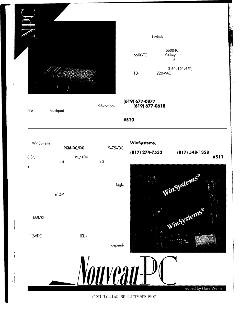
PULL-OUT DRAWER UNIT
The
Model 6600-K
provides a Windows
keyboard,
pointing device, and 10.4” active
matrix color flat-panel VGA monitor in a single pull-out
drawer unit. The unit makes a compact and complete
operator-interface solution for any standard PC. Installed in a standard
19” industrial rack, it requires only 3.5” of height.
This drawer unit is ideally suited for industrial conditions because its
sealed keypad and
security prevent unauthorized access on the
factory floor. If security isn’t a concern, the keyboard/monitor drawer
may be unlocked for instant accessibility. If you want to control several
PCs within the same rack, the
can be attached via expanders.
The
features a 1
keyboard with an AT DIN connec-
tor, touchpad, and two buttons. It Microsoft serial mouse compatible,
with an active-matrix SVGA
color flat-panel display and a
DA-15
analog connector. Measuring
the unit is available for
1
o
r
power requirements at 25 W. It sells
f
o
r
$
2
9
9
9
,
which includes the complete drawer unit, manual, and driver disk.
Industrial Computer Source
6260 Sequence Dr.
San Diego, CA 92
12 1
Fax:
www.indcompsrc.com
PC/ 104 DC/DC POWER SUPPLY
has introduced two DC/DC modules for PC/l 04
expandable systems. The
modules span a
input-voltage range. They are
PC/l 04
compliant, measure 3.6” x
and mount anywhere in a
stack.
Both single-output
V at 2 A or triple-output
V at 2 A and
12 V at 0.416 A models are available. The power supply requires
no minimum current loading on the output(s). It maintains regulation
on all output voltages down to zero current, eliminating the need
for load resistors.
The PCM-DC/DC family is based on two wide-input,
efficiency DC/DC converters-one supplies the +5-V DC output,
and the other, the
DC output. The PCM-DC/DC-12 nominal
input voltage is 12 VDC, but it accepts 9-36 VDC. The PCM-DC/
DC-48 nominal input voltage is 48 VDC, but it accepts 18-75 VDC.
Each power supply has short-circuit protection and an in-line
fuse on its inputs. As well, each module has a six-sided metal case
for
protection and an I/O isolation of 1500 VDC.
Overvoltage protection is provided on each output.
A 4-pin standard connector (disk-drive style) located on the
board edge makes it easy to test and power a system with a
+
local power supply. Three
provide a visual status of
each power-supply voltage.
List prices for the modules range from $150 to $250,
ing on configuration.
38
I n c .
715
Stadium Dr.
l
Arlington, TX 76011
l
Fax:
www.winsystems.com
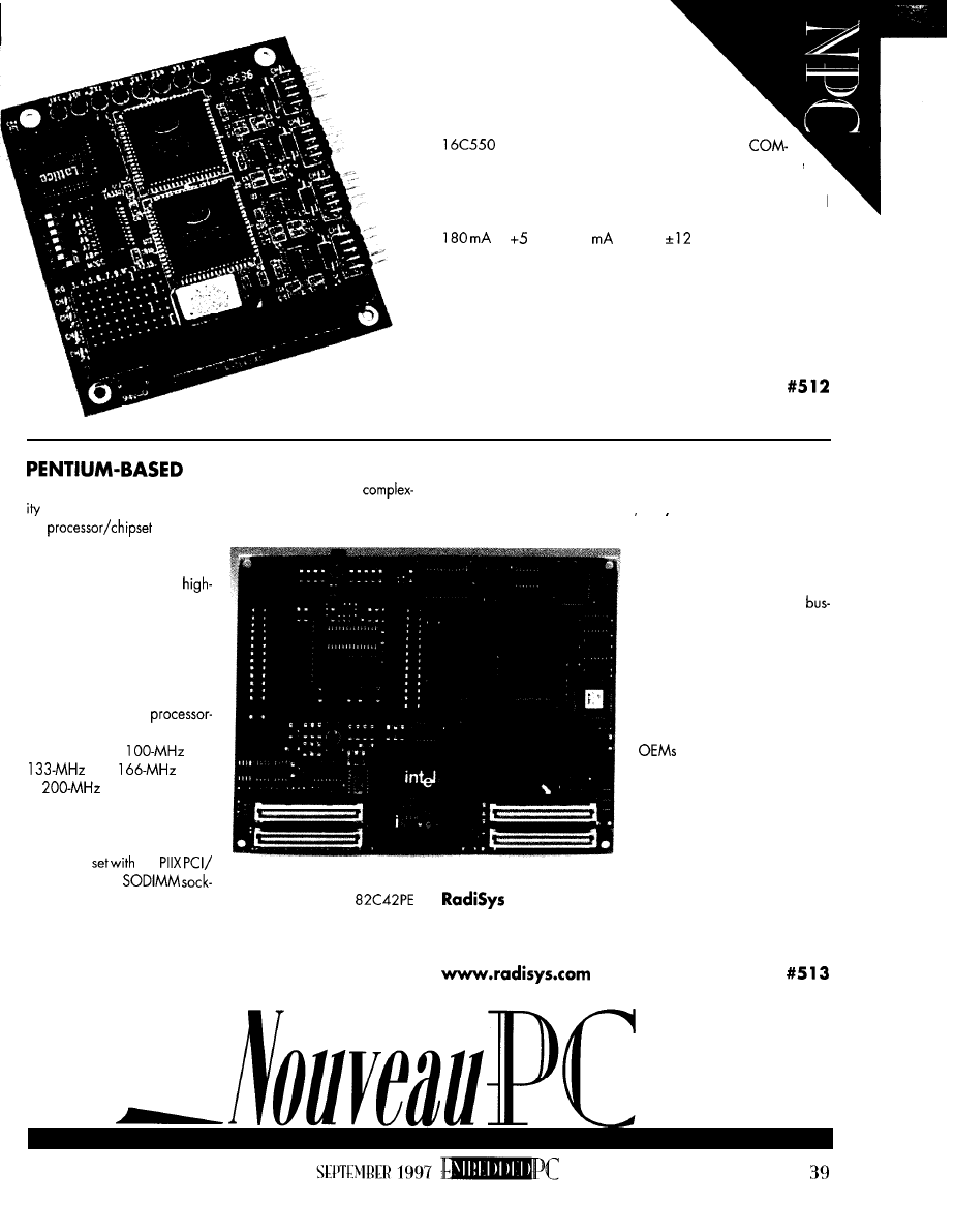
QUAD RS-232 MODULE
The PCM-3460 is a high-speed, four-port
RS-232 serial interface module in the PC/l 04 form
factor. It uses the fully programmable, industry-standard
UART to provide four independent RS-232
compatible serial interfaces at speeds up to 1 15 kbps. The
module also features LED activity indicators, jumper-selectable
COM ports and interrupts, full RS-232 interface support, and
compatibility with PC software drivers. Power requirements are
at V and 70
max at
V.
The PCM-3460 sells for $205 in quantity.
Versalogic Corp.
3888 Stewart Rd.
Eugene, OR 97402
(541) 485-8575
Fax: (541) 485-5712
www.versalogic.com
MODULE
The
EPM- 1
embedded processor module reduces the
of Pentium processor-based embedded designs by separating
This module interfaces to a specially designed I/O baseboard
via four connectors for the PCI. ISA. and IDE buses, reducing
the
core from
the application-specific portion
of the design. This setup isolates
the I/O circuitry from the
speed electronics associated
with Pentium designs and pro-
tects the I/O portion from being
affected by future changes in
processor architecture.
This compact, integrated
4.2“ x 5.3” Pentium
based CPU board is available
with a choice of
STD,
VRT,
VRE,
or
Pentium processor
with MMX technology. It has all
the essential elements of a com-
puter core, including the Intel
430HX PCI
the
ISA accelerator,
interface to the I/O baseboard
to a set of well-defined low-speed
signals. The fastest of these sig-
nals-the PCI bus-runs at
33 MHz and works across
connector interfaces. The board
is designed to stand high enough
above the I/O board that cir-
cuitry can be laid on the board
below it, enabling compact base-
board design.
The EPM-1 can be used by
to develop a custom em-
bedded computer, or it is avail-
able as part of a wide range of
embedded computer architec-
tures. Prices range from $478 to
$941 in 1 OOO-piece quantities,
depending on configuration.
ets accommodating up to 256 MB of DRAM, and
Corp.
keyboard/mouse controller. The board also contains a processor
5445 NE Dawson Creek Dr.
power supply, L2 cache memory, real-time clock, battery-backed
Hillsboro, OR 97124
CMOS RAM and clock synthesizer, and flash-based configurable
(503) 615-1100
l
Fax: (503) 615-1150
Phoenix BIOS.
fmon N
m
rivers
PC
less
less
time
to
design
product, it’s
even
more important
to
streamline
he
design cycle. Simon
shows
how writing
device drivers via
code
the
schedule,
reduces
errors,
organizes a
team’s
code.
bedded systems, particularly in com-
munications, are growing rapidly in re-
sponse to the demand for faster and easier
access to data and people. As a result,
microcontroller vendors are developing
tailored processors with specialized func-
tionality embedded in the periphery.
While these processors enhance system
performance and enable designers to de-
velop new features, configuring and using
their complex peripheral functionality is a
major headache.
Writing and testing device drivers is a
challenging interdisciplinary task requir-
ing in-depth hardwareand software knowl-
edge.
The
automation means this phase
is a center of risk in terms of schedules and
costs, as well as an ongoing source of
maintenance problems.
In this article, look at the increasingly
important role device drivers play in em-
bedded systems, the growing challenges
of writing them, and the options available
for dealing with these challenges.
ROLE OF DEVICE DRIVERS
As Figure
1
illustrates, device drivers
are central to embedded system design.
With peripherals consuming 50% of the
die area and functionality in advanced
microcontrollers, configuring and using
them efficiently is key to performance and
capability of the final system.
Drivers are also central because they
touch most aspects of the design. They link
the applications code to the microcontroller
and enable the hardware to be fully tested.
Device drivers unlock the power of the
microcontroller. They are important to per-
formance because they’re called repeat-
edly, and they dictate real-time perfor-
mance both in terms of response time and
use of memory and other resources.
Device drivers compose the layer inter-
facing the hardware to the software. As
well, they can dictate the time required for
system integration.
Various groups require different device
drivers for a myriad of tasks. The
development team needs them for system
testing. The software team needs a produc-
tion set of drivers. And, the production
engineering group needs a set for product
testing.
Writing device drivers by hand is so
lengthy and difficult that designers are
often unable to fully use the microcontroller’s
peripheral capabilities. Performance is
sacrificed, time is wasted in integration,
and different groups have to be satisfied
with a less-than-optimum, one-size-fits-all
compromise.
Rewriting device drivers is a specter that
haunts the program manager and
result in reluctance to move to new
microcontrollers.
The result can be unacceptable devel-
opment delays and lack of performance in
the end system.
But, in a competitive market, it’s essen-
tial to fully use the performance of the
microcontroller and minimize development
time and cost (see
“Methodology,
Hardware Independence, and Automation
are Key to Efficient Innovation”).
41
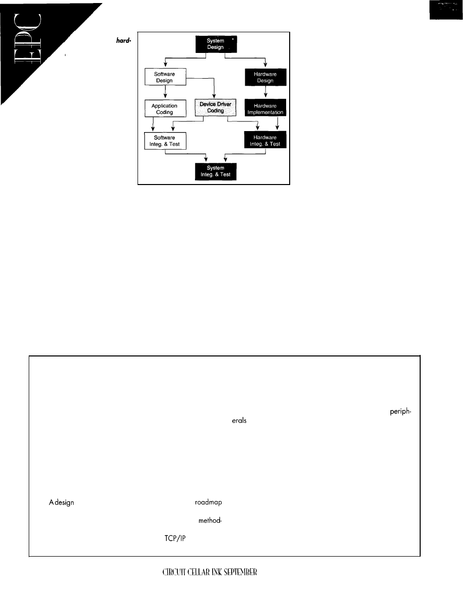
Figure I-Device
drivers touch
ware and software
design.
WRITING DIFFICULTIES
Driver design and implementa-
tion isn’t especially difficult in terms
of algorithmic complexity, but it is
demanding in terms of the sheer
volume of data that must be coded.
Device drivers are unforgiving-one
small error will cause an entire sys-
tem to fail.
Software
Configuring a set of peripherals
often means setting over 1000 bits of data
in over 60 registers. If you get one bit
They are the key to the puzzle of integrating
the hardware and the software to perform
system-integration testing.
wrong, the whole system fails. And, trying
to track down that one wrong bit is a
debugging nightmare.
Writing device drivers is an interdisci-
plinary skill requiring extensive hardware
and software abilities. You must under-
stand the peripheral’s details and be able
to configure them to meet the requirements
of the end system.
When you find a problem, it is not clear
whether it’s the hardware, the drivers, or
the software. You have to sort out where
there’s misinterpretation of how the drivers
are used, when there’s a bug, and what its
source is.
You must also have enough software
skill to build the layer so the applications
writer can interface to the driver easily and
intuitively.
This process must all be done at a point
in the design cycle where there’s no room
for mistakes and no opportunity to recover
lost time.
COSTS
The final challenge is that device drivers
The costs of writing device drivers can
Writing, debugging, and documenting
a library of device drivers constitute one
area of consideration. This process is some-
thing that can be outsourced with a defini-
tive cost. But when developed inside, costs
are less easy to quantify.
Hidden costs include the time it takes to
manage the activity plus the overhead of
interfacing with the users and ensuring that
the requirements are well understood. For
complex microcontrollers, this task takes
anywhere from four to twelve months of
engineering effort.
Theengineeringcostof integrating hard-
ware and software is where the device
drivers enable the system to be integrated.
It’s also where any misconceptions or bugs
become obvious.
Although you’re still dealing with device
driver creation and debug, two other teams
now depend on the results. Any rewriting at
this time creates quite a production bottle-
neck. The cost of rewriting is multiplied by
the number of people kept waiting.
Documentation and maintenance are
the initial and ongoing costs of ensuring
that the system is maintainable and that
minor enhancements and updates can be
managed. They typically require one to
three months of engineering effort.
Obviously, these costs can vary. How-
ever, cases of device drivers taking 18
months to develop and integrate are not
uncommon,
with costs ranging from
are virtually impossible to test in isolation.
be placed in one of three categories.
$70,000 to $200,000.
Methodology, Hardware Independence, and Automation are Key to Efficient Innovation
Embedded-system designers know too well the pressure to
A key element of an embedded design methodology is to
turn out new products more quickly. Unfortunately, today’s
achieve hardware independence. Using high-level languages
processes for designing and implementing embedded systems
removes the designer from the processor. In embedded-system
are often slow, costly, and error-prone. Adding bodies to the
design, however, coding for the on- and off-chip peripherals is
design team often complicates rather than solves problems.
still hardware specific. Every time processors or off-chip
The time has come to better leverage the time and talents of
change, substantial low-level code must be rewritten,
a limited engineer design pool, so you can focus on innovating
affecting productivity and often introducing hard-to-find errors.
new products or reimplementing old ones. This leveraging can
This problem is becoming acute as manufacturers turn out
be accomplished via:
families of processors with specialized peripherals that radi-
cally change the price-performance equation.
l
development of structured design methodologies
To meet reduced design cycles, engineers must be relieved
l
tools that enable hardware independence
of implementation details and get usable code from a high-level
l
tools that automate manual and error-prone design steps
specification. Tools that generate tested and documented code
from a functional specification (e.g., the Driveway 3DE tools)
methodology-ordesign flow-provides a
handle such mundane, error-ridden code in a timely manner.
for continual improvement. It lets companies define bottlenecks
Of course, there are always tradeoffs. A methodology that
and provides standard design interfaces. A consistent
enables a team to work cohesively overrides individual design
ology also gives an essential framework for code reuse and
style. Designers can no longer write all the code. But, the loss
integration of standard components (e.g.,
stacks) that
of control lets the engineer focus on the elements deemed
are more efficient to buy than build.
critical to the end product.
42
1997
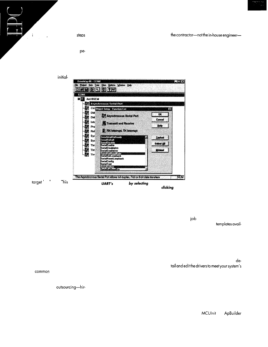
DEVICE DRIVERS
Building a setofdevice
drivers and integrating them
into the svstem reauires six
for each peripheral:
l
learn the microcontroller-learn the
ripherals and what they can support,
the register map, how to configure each
peripheral’s mode of operation, and
how it behaves during operation
l
design drivers-define
ensure that no surprises crop up later in the
design cycle. There are several things to do
before the device drivers are written and
throughout the coding process.
First of all, invest in training. These
microcontrollers can be very complex, and
a training session helps ensure that you
have the most up-to-date information about
the chip.
Define the functions that are required
early. All required functions should be fully
all the inherent problems of the do-it-your-
self approach.
And, when the project is complete, it’s
who has the knowledge about the drivers.
So, it’s difficult to change the drivers when
a feature changes in the application or a
bug is found.
If you’re doing to work with an outside
vendor, follow these tips.
Check that the contractors are already
ization sequences, normal op
eration, and error conditions
handling
l
c o d e d r i v e r s - e n c o d e t h e
mode of operation and docu-
ment the calling sequence for
the applications writer
l
debug-one of the most chal-
lenging tasks. A single incor-
rect bit in a register can cause
the entire system to fail. As
well, it’s difficult to test the
code when no hardware is
available, making debugging
a tedious trial-and-error pro-
cess.
l
integrate-the debugged driv-
ers are integrated into the
application software and run
.I
on me
hardware. I
step often involves another
Photo l-Define the
functions
the Asynchronous Port,
selecting the Transmit and Receive operation, and
on the
lengthy debugging process.
functions required by the application.
l
document-sufficient docu-
mentation is needed for maintaining
and supporting drivers. Documentation
covers the function names and algo-
rithms, calling sequences, restrictions,
and examples.
A microcontroller may have 20 or more
peripherals, and each manufacturer re-
quires its own set of device drivers.
CREATING DEVICE DRIVERS
Today, the task of creating device driv-
ers is typically handled in one of three
ways. Most
is the “do-it-yourself”
approach where the system designer writes
the drivers by hand.
Another approach is
ing a consultant to write the drivers. Finally,
and most promising, are the latest automa-
tion tools beginning to emerge. Let’s review
each of these approaches briefly.
For the do-it-yourself approach, it’s nec-
essary to invest sufficient effort up front to
44
discussed, and the usage and calling se-
quences must be documented.
When you code, keep in mind that
changes are likely. So, carefully document
the code and ensure that it is possible to
add or change functions.
As soon as possible, test the code. Invest
in a separate board that allows functions to
be tested in isolation. This process helps
minimize the source of bugs later in the
project.
As a final step, document fully what’s
done, and give the applications software
writers a complete set of documentation so
they know how to use the driver code.
With outsourcing, on the other hand,
it’s possible to buy expertise for a particu-
lar microcontroller and application, thus
reducing the time required for learning the
hardware and software (perhaps shaving
a couple of months off the process).
However, driver creation, debugging,
and integration are still done by hand with
CIRCUIT CELLAR INK SEPTEMBER 1997
expert in the processor. (Don’t
pay for them to become ex-
perts on your design.)
Allow room in. the budget
for changes, maintenance, and
training. It is not just the drivers
you want. You need to know
how to use them. And, be sure
you build changes into the cost.
From the start, make sure
your requirements are as clear
and well understood as pos-
sible. Although you’ve bud-
geted for it, you want to mini-
mize changes.
As well, verify that docu-
mentation and training are in-
cluded in the bid. These drivers
will have to be maintained,
and documentation is critical
unless the outside contractor is
going to maintain the drivers
indefinitely.
Although automation tools
are just beginning to emerge, this ap-
proach shows the greatest promise. Some
tool options are already available to help
you get the
done faster.
Drivercodesamplesand
able on the Web can be downloaded for
use in development. These templates pro-
vide a generic set of device drivers for
specific microcontrollers.
Although they provide a head start,
templates still require a great deal of work.
You must understand the hardware in
specific peripherals and functions. Also,
there’s no tech support if problems arise
while you’re adapting the template.
To date, the automation tools available
for designing device drivers have been
limited to free help tools that enable you to
explore the microcontroller and learn its
features more quickly.
Tools such as
and
also provide some templates as starting
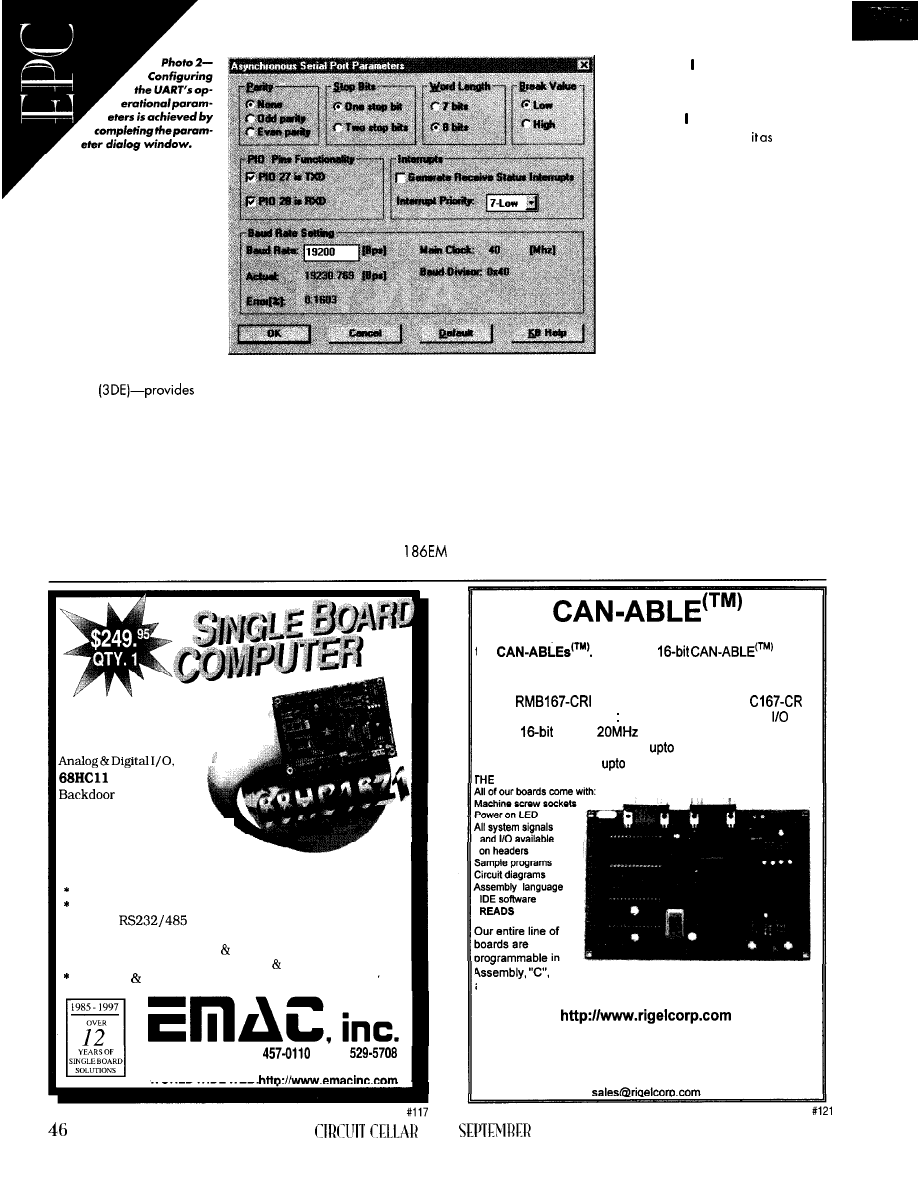
points for devicedriver de-
sign. They help you through
the first step but leave the
remaining steps to be done
by hand.
A n e w t e c h n o l o g y - t h e
Device Driver Design Envi-
ronment
a morecomplete
automation solution.
The 3DE encapsulates the micro-
controller with a personality database built
from tuned, documented device-driver mod-
ules that are fully tested on hardware. The
database also includes controller-specific
help and data to aid the learning process.
The 3DE lets you select the functions
needed to control each peripheral and
then combine them with specific variables
(e.g., buffer size, crystal frequency, memory
locations). Then, it tiles the code fragments
together and produces a complete library
of device drivers.
UART EXAMPLE
Let’s discuss what’s required to config-
ure one of the peripherals for a system
using an AMD
microcontroller. In
this example, built one of the device
drivers to communicate to a monitor
(dumb terminal) using a UART. To
achieve this, used the asynchronous
serial port and configured
a UART.
I chose the Driveway-86 to config-
ure the peripheral. But, whether con-
figuration is done with an automation
tool, by a contractor, or on your own,
the same data must be generated.
The 3DE provides a logical and
efficient approach for defining what
you need to know before you start
coding. So, no matter which method
you use for writing the driver, it out-
lines an effective hierarchical design
methodology.
driver in this example. However, some
important work is still required up front.
I’m just implementing one device
The relative priorities of the interrupts
need to be assigned, and the buffer sizes
and exceptions need to be defined. It’s
essential to work these out at the start since
they can be very time consuming to work
out after the event.
The next step is to configure the
peripheral’s mode of operation and define
This board comes ready for
demanding
applications,
with 16 bit
DSP capability,
and
Compatibility.
Debug and up
to one Megabyte of battery
backed RAM creates a robust.
development environment.
* 16 Programmable l/O lines
* 8 High Drive Digital Outputs
8 Channels of Fast 10 bit A/D
Optional 8 Channel, 8 bit D/A
* Up to 2
Serial Ports
* Backlit capable LCD Interface
* Optional 16 Key, Keypad Interface
* 16 bit Timer/Counters with PWM Clock/Calendar
64K RAM EEPROM included plus Flash Capability
618-529-4525 Fax
BBS
11 EMAC
WAY, CARBONDALE, IL 62901
WORLD WIDE WEB:
RIGEL Corporation introduces its newest line of boards,
the
Our 8 and
boards
are designed for immediate placement into a
Controller Area Network.
The
features the Siemens SAB
processor, and includes an RS232 serial port, 111
bits,
five
timers,
system clock, built-in CAN
interface, 4 channels of PWM,
1 MB of FLASH memory
and
1 MB of SRAM.
RIGEL DIFFERENCE
snd Forth.
FOR MORE INFORMATION VISIT OUR WEB SITE
or contact us at
RIGEL Corporation,
PO BOX 90040, GAINESVILLE, FL 32607
Telephone (352) 373-4629 FAX(352) 373-1766
INK
1997

Listing la--The initialization function of the serial port relies on the definitions file for the
serial port. b-The definitions file is automatically generated and documented for the user.
void
= 0;
= 0;
Serial ISR to int. tbl
Sets serial-port int priority level and unmasks this int.
Note! Priority level is also set at int-controller code.
Disable serial port
Clear status reg
offset
Read pending rx char to clear
RDR bit at status reg
Set baud-rate divisor
Sets Serial Port Control Register
Offset
Set TX, RX and Status mode
(LOOP)
Send Break
Break Value
Parity Mode
Word Length
Stop Bits
+
+
ONE-STOP-BIT +
+ TMODE +
+ RMODE +
Sets Serial Port I/O pins.
pins also set at
code
Set PI027 as TXD pin
Set PI028 as RXD pin
Definitions
40
main
rate
#define
0x40 Divisor for internal
generates
on phase (half period) of serial
#define
19200L
serial port baud rate
7
Serial port int priority
Variables
extern volatile
Serial port Rx buffer length
extern UINT8 *
Serial port Rx buffer
extern volatile
Length of TX buffer
extern UINT8 *
Pointer to TX buffer
the
functionsthatcomposethedevicedriver.
It'simportanttotradeofftherichnessofthe
functionsagainstthesizeofthedrivercode.
took the typical
function set shown in
Photo
you
seehowtheserial port
will operate as well as the
list
of
functions
that the
applications software can access.
Now, I need to define how the lower
level functions operate
the
hardware. The
panel in
Photo 2
lets
you
define
the
details
of
the
communications and its interface to
the hardware.
Havingworkedthrough anddefinedthe
peripheral's operation, the required func-
tions, and the operational parameters, it's
possibletocodethedrivertospecification.
Jumping into the coding process can
lead
to extra work and extended
mentschedules. Defining the operation so
rigorouslyhelpsminimizedevelopmenttime,
but
it’s vital to document code
clearly.
Whiletherearemanycodingstandards,
ensuring that the code is well enough
documented for someone
else
to pickitup
later is a minimum requirement. Bear in
mind that documenting the code will be
leveraged, since it can be used as part of
the documentation package
you supply
to
the applications writers.
Listing shows a restricted example
eralsaregiven prioritythroughan interrupt
scheme. However,
onstrates the complexity of
writing the drivers for one
ripheral and the value of a
design methodology. Using a
structured approach lets you maximize
.
the value of the documentation and coding
and helps pinpoint errors.
.
However the device drivers are written,
automate the process as much as you can.
Use templates where possible, and reuse
what you can. And, assume that changes
will be necessary, so keep the code easy to
read and migrate.
EFFICIENCY SUCCESS
Writing device drivers is a hidden key
to successful products. They play a central
role in determining much of the perfor-
mance and to what extent you can
age the capabilities embedded in the
microcontroller’s silicon.
They are also complex and can dictate
the time it takes to deliver the design to
production. It seems likely that the complex-
ity of peripherals will continue as new
silicon technology enables more and more
to be encapsulated on a single micro-
controller.
So whether you write drivers yourself or
outsource them, it makes sense to apply a
rigorous methodology and use as much
automation as possible.
Simon
Napper is vice president of market-
ing for Aisys. He has held a number of
technical and
marketing positions in the
U.S.
and Europe and, prior to joining Aisys,
was vice president of
marketing for
Design Technology. You
may reach Simon
at
SOURCES
Driveway-86
Aisys, Inc.
4633 Old Ironsides Dr., Ste. 105
Santa Clara, CA 95054
(408) 327 8820
Fax: (408) 327 8830
Advanced Micro Devices, Inc.
P.O. Box
Sunnyvale, CA 94088
(408) 732-2400
IRS
410 Very Useful
411 Moderately Useful
412 Not Useful
PC/7
04 enables precise mofion control
reach
guides
the
reader
of
choices need be made
when
04
and
mofion control come
together.
any motion applications may be ad-
dressed by the simple on/off I/O methods
thateveryone’sfamilarwith. Precise motion
control, on the other hand, requires
speed control of actuators (e.g., motors
and hydraulics] via computers or
Typical motion applications range from
simple material handling along one axis to
robotics involving many axes of coordinated
motion, and
Modern controllers
control position with submicron accuracy
and velocities to less than 0.0 1% tolerance.
When motion has to be precisely coor-
dinated, computer systems generally pro-
vide the control. But, writing motion-control
algorithms that adequately handle real-time
update requirements within a specific ap-
plication time frame isn’t easy.
Off-the-shelf motion-control products are
designed to handle real-time motion require
ments and integrate simply into your appli-
cations. Both servo and stepper motor
controller devices are available as add-in
boards for several industrial standard mi-
crocomputers-including PC/l 04.
The flexibility gained from motioncon-
processors or
gives designers
more powerful predefined algorithms for
designing board-level control. Hence, the
art to control is coordinating the needed
motion with machine timing requirements.
Obviously, you don’t want to reinvent
motion software. But, software written for a
single computer environment isn’t neces-
sarily the best answer.
A single processor-be it an XT, ‘486,
or even a DSP-is usually tasked to the limit
when calculating, processing, and control-
ling more than four axes of linear servo
motion and two axes of circular algorithms
in the time required to maintain smooth
motion and accomplish collateral tasks.
Truesingle-level multitasking isachieved
via single-board multiple-axis motioncon-
trol cards in systems operating under soft-
ware control. They enable faster motion
update periods (under 256
per axis) for
any number of axes, solid machine control,
and, with the proper I/O board, increased
system flexibility and modularity.
SEPTEMBER 1997
WHY PC/
Of all the system types on the market,
what does PC/l 04 offer motion control?
In industrial applications, cabinet space
is at a premium.
yields the most
operational capability in the smallest avail-
able footprint.
Since
uses open-frame con-
struction, dedicated cooling fans may not
be required, especially if they’re installed in
industrial
by
fans.
With a
PC/l 04 system, you can
install multiple processor cards on a single
card-cage bus. One card handles the opera-
tor or perhaps both machine and operator
safety needs, while another handles system
operation. You then get the best real-time
solution withoutlosing performanceorsafety.
The open structure of PC/l 04 systems
also provides easier access. To replace or
add a card in a
system, just pull
apart the bus and service the board. By
contrast, a PC board requires the removal
of one or more cabinets and at least one
fastener per board.
49
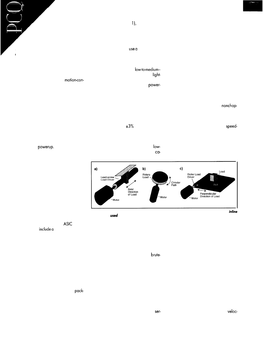
Obviously, in indus-
trial environments, the time
needed to service or access a
board is part of customer down
time. Although 10 minutes doesn’t
sound like much down time, if you
service an operation that runs at 30’ per
minute with product costing $40 per foot,
the customer loses over $1200 per minute!
I/O option boards for PC/l 04 offer a
wide variety of control capability. Engi-
neers can therefore take a more direct and
noncompromising approach to
trol design with minimal effort.
E N C O D E R B A S I C S
Optical encoders fall into two basic
categories-absolute and incremental.
Output from an absolute encoder repre
sents the absolute position of the encoder
rotor to within one shaft rotation. Each bit
of resolution requires additional coding on
the optical disc.
The primary advantage of an absolute
encoder is its ability to give absolute position
information at
Its disadvantages
are the larger code disc size and higher
cost associated with increased resolution.
Incremental encoders fall into several
subcategories-pulse (tachometer), pulse
and direction, up/down, and quadrature.
When designing in encoder feedback,
consider both system and encoder resolu-
tion, maximum encoder output frequency
(pulses or lines per second), maximum accel-
eration rate needed for the encoder, and the
interface (voltageand current) requirement.
S E R V O - S Y S T E M B A S I C S
Servo controllers come in several styles
including DSP, processor, and
based.
Typically,
they
feedbackcounting
mechanism, a gain structure that coordi-
nates the actual and desired system posi-
tions, and an output interface signal to
control the motor. These elements ensure that
the system load reaches the command
position via the requested move profile.
The system load, inertia, profile, environ-
ment, and similar factors govern
the
choice
of any motor/amplifier package. The electri-
cal and physical differences of the motor
types listed in Table 1 offer enough perfor-
mance variety for you to judge which
agesatisfiesyoursystemneedsand budget.
When designing a system with a servo
motor, consider the system and encoder
resolution, as well as the maximum velocity
and acceleration rate. Also, thinkabout the
system type (see Figure
system inertia
and stability, and the motor amplifier power
and current requirements.
If your application requires high-speed,
short index moves or short duty-cycle moves
with high torquecontrol,
DC brushless
servo. It gives a high power-to-size ratio and
high acceleration/deceleration capabilities.
A PWM DC brush servo motor works well
for long, high-speed moves,
speed short moves, or index moves with
to-medium loads. This motor needs brush
replacement and provides medium
to-size ratios, armature inertias, and accel-
eration/deceleration capabilities.
Stepper motors provide low-to-medium
acceleration/deceleration along with high
power-to-size ratios. For any application,
check how the stepper performson its speed,
torque, and curve. A stepper’s positional
accuracy is generally
of a full step but
can be less for a higher cost.
General-purpose DC motors aren’t de-
signed for true servo applications, but they
can move light-toheavy loads requiring
to-medium acceleration/deceleration
vos sometimes end up in applications oth-
erwise ideally suited for stepper systems.
toad inflections, acceleration rates, top
velocity, high-velocitytorque reduction, zero
following error, and other factors all contrib-
ute to the success of a stepper application.
S T E P P E R C O N T R O L L E R S
It’s critical to understand both the opera-
tional and system-reaction differencesamong
various types of steppers. For example, a
chopper drive always causes stepper motors
to vibrate when not commanded to move.
In photo-film handling, a vibrating step-
per motor directly coupled to a drive roller
can cause the film to vibrate, which is not
acceptable for positioning, developing, or
splicing. A bilevel current-limited,
per-type drive is a better system fit.
If the translator is current limiting via an
external resistor, the power-supply voltage
may be increased, improving the
torque curve. However, consider power
supply limitations, external resistor power
dissipation, and motor driver constraints.
Two common translators, as defined by
current flow, are bipolar and unipolar.
Figure l--There are three basic motor motion styles, each with their own applications. The
motor [a) is
primarily
for CNC applications, while the rotary(b) and tangential (c) systems
are used for robotics and conveyor/material handling, respectively.
pabilities. They’re well-suited for velocity
mode and low-accuracy positioning.
AC motors-brushless servo, vector, or
any other variety-provide low-to-medium
acceleration/deceleration capabilities,
moderate servo positioning using
force on/off control, and medium-to-high
armature inertias.
S T E P P E R B A S I C S
While servo systems seem to be favored
over stepper systems, the latter has recently
gained attention through breakthroughs
like microstepping and five-phase control.
But since stepper motion operating in
open-loop mode is more complex to control
and requires more preliminary analysis,
Both are available in resistance-limited,
bilevel, VSI, and two- and fourquadrant
chopper models.
The microstep translator is so-named
because the stepper motor’s current-gener-
ated magnetic field enables the armature
to be positioned anywhere between its
actual detent positions. The most popular
microstep ranges available (at reasonable
cost) are 2, 4, 8, 16, 32, 64, and 128
steps per full step.
S T E P P E R M O T O R S
When designing
a
steppersystem, think
about the required maximum resolution,
accuracy, repeatability, and step resolution.
Also, consider the maximum needed
50
CIRCUIT CELLAR INK SEPTEMBER 1997
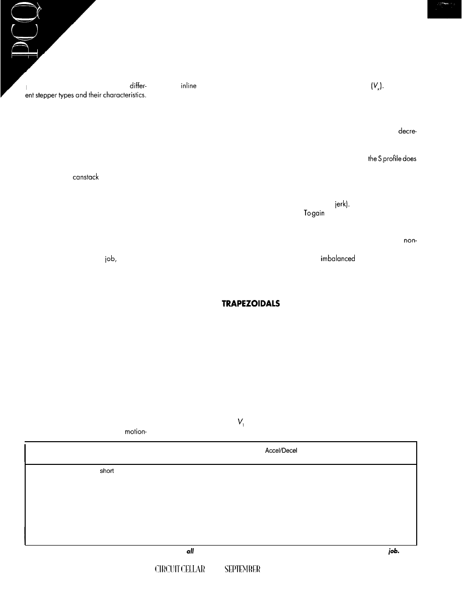
ity, acceleration rates,
system type, inertia, and
the stability of the product to
be handled.
Once you address these issues,
you greatly improve your chances for
project success. Table 2 lists several
Be cautious of servo controllers where
voltage-to-frequency converters run the step
per. The nonlinearity of these converters
generally compromises that stability.
Some types of stepper motors include
the moderately priced variable reluctance
motor (i.e., a nonlinear device with
nonsinusoidal characteristics) and the non-
linear PM (e.g.,
or claw type).
The variable reluctance motor has no
magnets, operates at virtually any angle,
and has a good torque-to-inertia ratio, but
it’s noisy.
The PM is the lowest priced stepper
motor and is suited only for low-to-medium
power operation. Its bearings can affect
motion stability, and its step angles are
coarse. But if it can do the
the PM is
often the most effective choice.
The two- or five-phase hybrid is a mod-
erately priced, nonlinear device with good
availability. Detent torque depends on tooth
design, and it has good torque/watt accu-
racy. The hybrid is a moderate power work-
horse for limited duty.
The axial air gap disc rotor and en-
hanced hybrid cost more than other step-
pers. The axial air gap disc rotor is linear,
gives the best torque-to-weight ratio of the
group, is efficient and snappy, but has
limited power. The enhanced hybrid yields
the highest power output for a given driver
power rating.
MOTION-SYSTEM TOPOLOGIES
Three basic load-driving topologies, or
a combination thereof, define all
control applications. In each system type, if
more than one axis of motion is involved
because of mechanical design, you must
coordinate the calculations of each axis.
Small load changes in one axis can have a
substantial dynamic effect on the others.
The
system consists of a load mov-
ing in an axial direction to the load driver.
For instance, when a lead screw is directly
attached to the load and followed by a
screw follower, the load is transported in the
axial direction of the lead screw (load driver)
asthescrew rotates, osshown in Figure 1 a.
The rotary system in Figure 1 b consists of
a motor attached directly or through a gear
train to a load rotating about the load center.
The load needn’t be balanced or move in
a path around the load-driving device, but
it must move in a radial fashion.
The tangential system consists of a load
moving in a direction perpendicular to the
axial direction of the load driver (see Fig-
ure lc). In a simple conveyor belt, the
motion is perpendicular to the axial direc-
tion of the drive roller.
A rotating spindle exemplifies a typical
rotary system. It either rotates the work
(e.g., a lathe) or the tools that contact with
the work.
S CURVES AND
Trapezoidal and S-curve profiles are
the two main types considered when devel-
oping a motioncontrol requirement.
In the motion-control industry, “profile”
describes a complete and controlled motion
event. That is, the move accelerating from a
base velocity to a slew or run velocity,
continuing at the slew velocity to a desig-
nated deceleration point, and then deceler-
ating back to the base velocity.
Base velocity doesn’t have to start at
zero. A profile can begin from any previ-
ously established velocity and be con-
sidered complete at any other velocity.
In a trapezoidal profile, theacceleration
and deceleration rates of a motion are con-
stant, as you see in Figure 2a. The velocity
accelerates linearly until the profile reaches
the required slew velocity. During decelera-
tion, velocity decreases linearly until motion
reaches its target velocity
By contrast, an S-curve profile is a
controlled velocity (or ramped acceleration)
profile. As Figure 2b shows, the S curve is
more complex than a trapezoid since it’s
based on two linear incrementing or
menting variables over time.
A trapezoidal profile applies only half
as much torque loading as
at halfway up thevelocity profile in the same
time frame. However, the S curve generates
a softer move at the profile’s leading and
trailing ends, thus lowering impulse torque
loading (i.e.,
Medium-to-high friction systems,
counterbalanced vertical systems, or other
similarly
systems may defeat
S curve’s ability to perform. Gain structures
can be implemented to overcome this defi-
ciency.
theseadvantages, carefully match
the update timing for the S acceleration
profile to system dynamics.
Using only a PID gain structure without
any other form of gain assistance, the S
curve may not perform any better than the
trapezoidal when placed in a high-friction
environment (above a 0.15 coefficient). The
same holds true when operating in a me-
dium-friction environment (0.075-O. 1 5 )
and applying a current motor operation
without tachometer feedback.
Interestingly, to achieve the same accel-
eration time versus distance, the peak ac-
celeration achieved at the S’s crossover is
twice that of a trapezoid. Wherever the
product is not secured to the conveying
surface, the G-force exerted on the product
may cause it to slip.
Motor
Type
Moves
Loads
Power:Size Armature
Ratio
lnettias
Capability
Notes
Brushless
High-speed
index
Heavy (high
High
Low-Medium
High
short duty cycle
torque control)
PWM
Long high-speed;
Medium
Medium Low-Medium
Medium
Low-Medium-speed
short index;
Light-Medium loaded index
D C
Low-Medium speed
Light-Heavy
Low
High
Low-Medium
AC
Low-High speed
Light-Heavy
Low
Medium-High
Low-Medium
Resolver to quadrature converter option
Brush replacement required
Velocity mode or low accurate positioning;
Not designed for true servo application;
Brute-force on/off control
Brute-force on/off control;
Moderate servo positioning capability
Table l-Selecting the correct motor is important since not
motors suit all applications. Make sure the motor’s capabilities
fit the
52
INK
1997

MONITORING THE
ENVIRONMENT
If you can see it, you can
control it. So, sensing devices lie
at the heart of any system. They must
work in the most extreme
vibration, dust, dirt, oil, grease, tempera-
ture, and electrical noise-and yet they’re
often ignored until they fail.
To ensure full sensor compatibility and
system integrity, it’s crucial to know the
application’s specifications for voltage, cur-
rent sink or source operations, propagation
delays, hysteresis, as well as any need of
solid state or hard contact, before a sensor
is selected.
Knowthesensor
the operational speed from the time the
action is sensed until the signal reaches the
controller-before selecting it. Know all the
environments it will have to operate in.
Endurance requirements, environmental
temperature, NEMA housing style, noise,
solid state versus mechanical, and many
other characteristics are critical to sensor
selection. Power source requirements (e.g.,
voltage, current and acceptable leakage
current levels, and AC or DC system opera-
tion) play a significant role.
Also, think about the properties of the
item to be sensed. Is it sensitive to light or
heat? Can it be touched?
These factors, along with accuracy and
repeatabilty requirements, are important in
choosing the appropriate sensor. But, it’s
the specific task to be accomplished that
defines the initial sensor requirement.
TIMING DIAGRAMS
The secret to coordinating multiple axes
of motion control with hundreds of possible
discrete I/O signals on a
lar machine is to design with the aid of
system or machine timing diagrams.
A
Position
B
The timing diagram is to a system what
a flowchart is to software. The timing map
specifically details theactions of the machine
parts and product at any point in the pro-
cess, both mechanically and electrically.
Once the system is ready for startup, the
timing diagram becomes your best debug-
ging tool. Since it serves as a function map of
the system, real-time machine operations
that require multitasking become immedi-
ately evident.
Figure 3 shows a timing diagram for
developing the operating requirements of
a rotary brush machine (used in floor buffing
and scrubbing machines).
shows
the required machine function operation
during a 360” head cycle.
Position
B
A 360” rotary head motion is converted
into linear motion and drills holes in round
wooden discs.
After
each hole is drilled, the
disc is indexed (without stopping the drill
head), which results in a circular pattern of
holes around the disc. At assembly, bristles
are inserted into the holes to form the brush.
Figure
trapezoidal profile has linear
acceleration and deceleration ramps. b-By
contrast, the S-curve profile has softened
ramps.
All this must keep up with a hydraulic
head that cycles at
rpm or one revolu-
tion in 0.24 Also, operators can load new
brush data from a master/host where new
brush patterns are produced, or it may be
producing daily work logs and set-up infor-
mation for building other brushes.
The actual machine uses five axes of
motion-two rotary and three in-line-op-
erating speeds up to 250 holes per minute.
An algorithm triangulates the positions of the
axes for disc tilting and radius place-
ment, while the rotary
axes
rotate thewooden
discs for drilling and bristle insertion.
While communications plays a signifi-
cant role in all of these cases, in the first
example, communications may be useful
only for loading or saving premade pro-
grams. But if you have nodes only, commu-
nications becomes the heart and soul of the
control’s capability.
selected so the system performs as needed.
If, when using node control, the ability
to synchronize axes is necessary, then an
off-the-shelf protocol that yields high-speed
A nodetypicallydefinesa small, compact
computer since a node takes instructions
data transfer has a definite advantage.
from a host at another location. The degree
or intensity of the communications, the inter-
face (e.g., Ethernet, RS-232, RS-485, etc.),
When using node control, you need to
and the communications protocol must be
answer the following questions:
COMMUNICATION
“Embedded control communications
protocol” can mean designing so that total
computer control, part of it, or none at all
(nodes only) is
the main system.
l
what’s the best way to format the data to
allow the fastest transfer of information?
l
how are very low data-transfer crash
situations between multiple modes
tained?
Stepper Types
cost
Linearity
Detent Torque
Angles
Notes
Variable reluctance
PWM (Canstack
or claw)
Two-/Five-Phase
Hybrid
Axial Air Gap
Disc Rotor
Enhanced Hybrid
Moderate
Lowest
Very nonlinear,
nonsinusoidal
Fair
No
(no magnets)
Significant
Moderate
High
High
Nonlinear,
but repeats well
Very linear
Fairly good
Depends on
tooth design
Depends on
design
Depends on
tooth design
Virtually any
Coarse step only
0.36-l 5” available
1.8” prevails
1.8” and 3.6” only
1.8” only
Noisy; Spins free; Good torque to inertia
Bearings can affect motion stability
Low-Medium power operation only
Best, if it can do the job
Limited duty, moderate power workhorse
Good torque/watt accuracy
Easy to model; Best torque to weight ratio
Efficient, snappy, but limited power
Models like the hybrid type;
Highest power out for a given driver VA
Highest power per volume
Table Z-While the correct stepper motor type is generally determined by the application, it’s also a balance of system performance and cost.
5 4
CELLAR
INK SEPTEMBER 1997
l
how much information needs to be trans-
ferred to maintain good-to-superior axis
control?
To answer, you need to understand exactly
how fast the communications required by
the embedded application should be.
While plotting might look like an inten-
sive operation, the real-time requirement is
loose. If the plotter has to wait while more
data is transferred, no loss of integrity is
noted. The data-transfer rate can range
from as low as 300 bps to 9600 bps.
On the other hand, a labeling unit at
1200’ per minute typically has a real-time
requirement of less than 250
for I/O
handling. Assuming 1
needed,
it takes only 0.0085 s to produce each
label. Using a xl 0 rule to ensure all label
data is appropriately transferred, the maxi-
mum allowable data-transfer time is 625
If each label contains ten characters, the
minimum transfer rate is 160 kbps, yielding
a new character every 62
The data rate
automatically eliminates the RS-232 proto-
col and requires a minimum of RS-485 or
Ethernet interfacing.
W ake Up, Address, Command Byte,
Bytes to Follow, Check Sum A, or one-byte
ACK or NAK are returned to the host,
verifying safe receipt of the message.
If multiple axes are used, messages can
be
acknowledged by pulling a common I/O
line low (NAK) or leaving it high (ACK). The
line shift would occur in the same timing
frame as the ACK and NAK bytes, but all
units might respond at the same moment,
increasing the band requirements.
While this transfer mechanism isn’t nec-
essarily the most efficient, it gives a high
probability that the embedded controller’s
messagesare being transferred intact, which
is exactly what we’re looking for.
let’s consider how to invoke move from
a remote hostwithout using upvaluable time.
The five basic types of move are immedi-
ate, point-to-point, time,
and stop.
I M M E D I A T E M O V E
An immediate move starts an axis
moving similar to a
routine. Velocity and
acceleration are downloaded to the node
along with the immediate move byte.
The velocity and acceleration informa-
tion can be modal, which means it stays in
effect until changed, so future mmed i ate
move commands comprise only the com-
mand and direction bytes.
P O I N T - T O - P O I N T M O V E
T h e p o i n t - t o - p o i n t m o v e i s u s e d
for simple axis motions. It’s well-suited for
operations like peck drilling, which uses a
mechanical drill bit or laser device.
Repeatable step motions enable this
operation to be accomplished
quickly
since
the distance to move can be relative motion.
In this situation, the move, along with the
velocity and acceleration, is modal.
T I M E M O V E
A time move moves the axis to a
specified position in a specified time. The
operator enters the ac-
.
but the velocity
to achieve the position in time
is calculated by the node.
Time movecanalsobemodalin
context, enabling simple repeatable
tion using only a command-byte transfer.
M O V E
For any controller-especially for em-
bedded controllers-s p 1 i n e move is the
most flexible form of motion. It enables the
host to send down complicated motion
files
with
a minimum of required commands.
IF YOU’RE
A PC,
TAKE A LOOK AT THESE
No, it’s not a very large chip, it’s a very
small computer. A complete,
386SX computer in a 240-pin
mount package just
that mounts on your board like a chip.
Harsh Environment?
Forget unreliable cables and vibration
problems. Everything you need is built
into the
It boots from its
internal Flash disk and even has 256K of
user available program space. There are
two COM ports, a parallel port, full core
logic, keyboard speaker ports,
and floppy disk support, and 2Mb of
internal DRAM with support for up to
64Mb externally. Only 5V at 2W (power
management sleep modes available).
Mounted directly on your proprietary
board, connections are rock-solid even in
harsh conditions.
A familiar platform.
The
is PC/AT compatible, so
all your standard development tools will
work perfectly.
BIOS DOS license included.
No licenses to negotiate. Power on the
and you have a DOS prompt.
The creator of the
concept brings
you more features per dollar than any
CPU on the market.
up to
DRAM
Flash, floppy, IDE,
4 serial, 2 parallel ports!
The
development kit comes
with everything you need to put your
project on the fast track to market:
hardware, software, schematic and
component libraries. It includes both AT
and
104 expansion busses.
Jointly developed by IBM
and ZF
for the transportation industry. Only 5.75”
x
8 serial ports, 2 parallel
ports, 51708 interface, slave processor
controls
multidrop network, and a
resident interface for GPS.
SEPTEMBER 1997
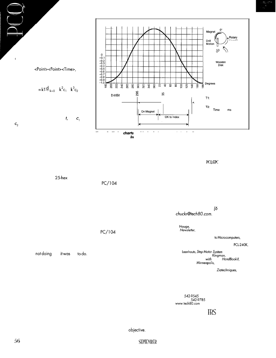
Target projection us-
ing cubic polynomials en-
ables the software to produce
continuous or discontinuous mo-
tion (e.g., sharpcorners). Withspline
motion, the cubic spline algorithm can
be the sole device producing straight lines,
circles, or any other coordinated motion.
The cubic spline algorithm can be given
in the form
so the
trajectory can be calculated by a polyno-
mial in the form:
Drill Height
1.0
0.9
0.8
0.7
Top Dead
Center
0.6
0.5
0.4
0.3
0.2
0.1
0
0 0
0
x(kt) + x
x +
+
d t
where k is the sample increment since the
start of the move, k = 0 is the time at the
beginning of the move, x(kt) is the target
velocity at each sample time and and
are calculated terms based on known
starting and transmitted ending values.
All Axes
Tumbler Clear
155” . .
100”
180”
START MOVE
Figure
S-Timing
enable the designer tooptimizefeedback requirements and motor type
v e r s u s c o s t . f o r i n s t a n c e , a r o t a r y s y s t e m
b
e
s
t
performance/cost ratio.
Start move
gets one or more axes
moving.Don’tuseitforimmediate move,
but it can be used for all other moves.
If single-axis moves are required, they
may or may not require a start command
depending on the variation of the specified
move. For example, a
command
byte makes a timed move after a start com-
mand is issued, while a 26-hex command
begins the timed move at message transfer.
selected. The PC/l 04 computer can be an
excellent choice. It’s small, cost-effective,
and easy to program. It also packages well
and uses minimal power.
Smaller may not always be better. But,
don’t believe that just because it’s small, it
can’t do the job.
Looking at the prime objective using
nodes, system capability is affected only if
the
system can’t support the re-
quired motion, I/O, or language.
Start move
gives the host at least
some control over the node, yielding a
higher degree of control flexibility.
Computerschosen for embedded appli-
cations should be industrially hardened
since they will be in environments noncon-
ducive to its electronic construction (e.g.,
welding and plasma cutting).
Chuck Raskin has written and lectured
extensive/y on motioncontrol issues. He
recent/y finished the fifth edition of Design-
ing with Motion Handbook. Chuck is an
American Institute of Motion Engineers
board member as well as manager of
technical service for Technology 80. You
may reach him at 12) 542-9545 or
STOP
REFERENCES
Stop is the most important motion com-
mand. Unlike steppers, which “like” to
stop, servo motors like to run away.
While running away doesn’t necessar-
ily imply being out of control, it does mean
the motion is
what
told
Thisfailuremay beduetomechanical break-
age or electrical noise, among other things.
It’s impractical for a node to always know
the actions of other nodes. The host, on the
other hand, should know what’s going on
within the system and be able to require all
nodes to stop whatever they’re doing.
The stopping action may be smooth,
decelerated, abrupt (full-power regenera-
tion), or a coast, which happenswhen motor
current is removed and the motor winds
down at its own rate.
PC/ 104 ADVICE
is a good little workhorse for
many embedded applications, and it fits in
most. It’s small and inexpensive, too, so
most customers won’t mind maintaining a
PC/ 104 inventory.
D.
“PC/l 04 Servo Software,” Technology 80
Technology 80, Minneapolis MN, Win-
ter 1991.
When choosing an operator interface
(i.e., keyboard and display), standardize
on it so you won’t find out you can’t do what
you want. And, practice with it before being
tossed into a situation. This will free you up
to focus on the application and not get
sidetracked with the PC/l 04 form factor.
S. Holle, Interfacing Encoders
Tech-
nology 80, Minneapolis, MN, Article 5.
S. Holle, Step Motor Control Using the
Technology 80, Minneapolis, MN, Article 7.
A.C.
Design Handbook,
Litchfield Engineering,
AZ, 1991.
C. Raskin, Designing
Motion
Tech-
nology 80,
MN, 1992.
Ziatech Corp., “Expanding PC/l 04 Bus Performance
Through Multiprocessing,”
9, 1990.
Based on the system’s move and real-
time requirements, a node controller is
And finally, when designing for embed-
ded operations, keep in mind that embed-
ding the control means more than just
sticking the computer into a machine cabi-
net. It means designing the computer into
the machine so it looks like an integral part
of the main design
SOURCE
PC/ 104 encoder card
Technology 80
658 Mendelssohn Ave.
Minneapolis, MN 55427
(612)
Fax: (6 12)
425
Very Useful
426 Moderately
Useful
427 Not Useful
Head Motion
1.5-l .o ms
Rotary Axis
Index To Next
Hole Location
Time to Index
Rotary Axis 7” (38 ns)
Absolute Max Rotary Axis
Index
is 133
(23.78”)
CIRCUIT CELLAR INK
1997

anagfng a
With our feet
planted
on the ground, it’s hard to imagine the adjustments
necessary to
a
experiment into space. Fred walks us through the
sensors and hardware he needs to truck humidity,, temperature, and
CO,.
the seagull flies, I’m 20 miles south-
west of Kennedy Space Center’s Pad 39.
have a perfect view of every orbiter launch.
If I’m not on the Cape proper, I stand in
front of my until the ship clears the tower.
A few seconds later, the windows reverber-
ate with the unmistakable sound of powerful
solid rocket motors, and a plume of white
smoke pushes the spacecraft upwards.
Within seconds, what I know to be a
rather large aerodynamic object is the size
of a pinhead. On a clear day, without the
aid of looking glasses, I can see the solids
separateand begintheirfall intotheocean.
I’ve seen nearly all of the launches, and
I always shake my head in amazement. All
that technology, men, and women success-
fully launched again into what we Earth-
lings call “outer space.”
Although it may seem glamorous, the
astronaut’s lob is hard work. If you step
back and look at this space-program thing,
one of the real needs for humans in space
is to tend the experiments that will ulti-
mately make life better for us back on Earth.
For some time, I’ve been close to one of
those experiment packages. And, thanks
to engineers at a space flight-oriented
panycalled BioneticsandMark”TheSpace
man” machinist, show you a day in the
life of another species of astronaut-plants.
T H E P G C
saw my first PGC (plant-growth cham-
ber) in Mark’s machine shop. Photo 1 gives
you your first look. After sleeping on it for
a few weeks, I decided to “embed,” in my
own way, the functionality of the PGC.
Electrode Fingers
Figure
sensor can play
The
grime mightrlowit down some, but it
be accurate.
1997
I’m not privy to some of the actual flight
hardware, software, and firmware, so
needed to select components to automate
and monitor the processes the PGC was
originally designed for.
Fortunately, through the generosity of
the Bionetics engineers, I got my hands on a
working PGC and the main sensor stock.
I’d already run this idea by Christine at
Tempustech, and she was
to sup-
ply the hardware.
Although Bionetics and Tempustech pro-
vided the bulk of what I required, need a
bit more hardware and software to embed
the PGC.
But
first, a PGC tutorial is in order.
PGC BASICS
The PGC is built using NASA-approved
polymers that strictly adhere to the safety
standardsofa manned-spaceflightprogram.
Six
fly in a special housing placed in
a
locker aboard the orbiter.
The PGC housing contains all the neces-
sary elements to promote plant growth. For
those of you new to this planet, that’s light,
57
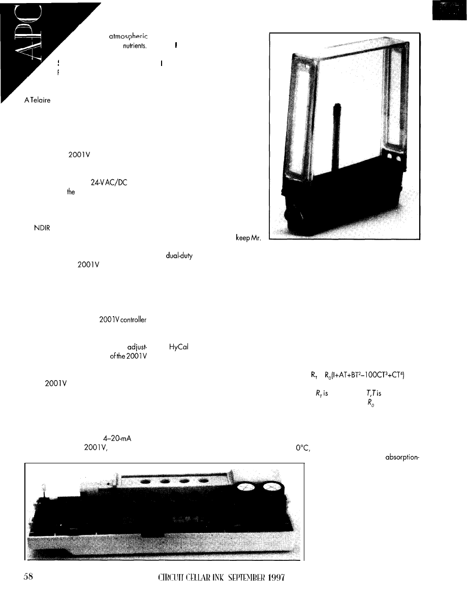
water.
gases, and plant
S E N S I N G C O ,
Plants like carbon dioxide. and
thanks to the presence of humans,
there’s plenty of that in the orbiter cabin.
2001 Vcarbon-dioxide monitor is
included to ensure the plants in each PGC
receive their prescribed amount of the gas.
CO, is gated to the PGC from the crew
cabin via a duct when gas levels fall below
nominal concentrations.
The Telaire
shown in Photo 2
was originally designed to monitor CO,
levels in the air and control a ventilation
system. That explains its
power
requirement. In
flight
package, the 2001 V
is removed from its decorative covers and
mounted within the PGC housing.
Carbondioxide measurements are taken
via
(nondispersive infrared). The sen-
sor comes from the factory equipped with
a membrane-covered samplechamber that
helps provide highly accurate readings.
Normally, the
is set to trip an
internal relay depending on the CO, con-
centration. The controller is factory set to
close the relay at 800-ppm concentration.
This trip value can be altered using the
UIP program. The UIP is a PC-based pro-
gram that interfaces to the
via an RS-232 connection and enables the
user to set the 2001 V’s sensor parameters.
The measurement range is fully
ableovertheentire bandwidth
sensor. The program also simulates sensor
environments and displays the results.
The
would be little more than
dead weight if it could only make decisions
on a predetermined concentration and trig-
ger a relay. The proportional O-l O-V analog
output voltage makes it a useful tool.
By simply swapping a jumper, the
200 1 V is also capable of
loop
operation. With the
the UIP, and
variable analog output, not only
can fully control environmental
objects by referencing
CO,
levels,
can log data, too.
S E N S I N G C O N D I T I O N S
Those of you who arrived from
other spaceports know that weight-
lessness is a fact of life when travel-
ing in space. During a weightless
sojourn, liquids find their way into
the worst possible places.
Since plants on Earth require
water, the PGC houses a sponge of
sorts in the darker portion of the
assembly. The sponge contains the
liquid and nutrient mix needed for
the PGC’s plant life. It also reduces
the probability of the liquid becom-
ing droplets that could foul up a
humanoid astronaut’s day.
Murphy and
his lawarecapable
of space travel, too. So, to
Murphy strapped tightly in his seat,
a
sensor called Survivor II
Photo I-Mork does good work, huh? Note the sensor
stock and the fancy latches.
is mounted within each PGC to monitor
humidity and temperature levels.
The
sensor is installed on a stainless-steel
mast. Theentireassembly (i.e., mast, sensor,
and connector) is known as the sensor stock.
Although our sensor has an integral hydro-
phobic filter, the hollow cylindrical mast
elevates the sensor well above the sponge
to prevent flooding the sensor’s face.
Survivor II uses an integrated platinum
RTD for temperature measurement. Plati-
num exhibits a very linear resistance versus
temperature function.
Sensing Products supplies the
Survivor II Relative Humidity Active Sensor
used in the PGC. It’s a +5-V CMOS inte-
grated circuit with a thin-film RH sensor
embedded in a monolithic structure.
Although less sensitive than some other
metals or thermistors, platinum provides an
accurate and sensitive way of measuring
temperature over time. Platinum’s resistance
versus temperature function is modeled by
the Callendar-Van Dusen equation (its con-
stants are shown in Table 1):
=
Output is a voltage proportional to the
relative humidity. Each Survivor II is factory
calibratedand hassensor-uniquecalibration
voltages for 0% and 75.3% RH. Humidity
voltages are referenced to the sensor power
ground. My PGC’s sensor outputs 0.807 V
at 0% RH and 3.015 V at 75.3% RH.
where
resistance at
temperature
in degrees Celsius, and is resistance at
0°C.
My RTD measures 1 k at 0°C. The RTD
resistance is available on two pins of the
Survivor II metal TO-5 sensor casing. At
the RTD measures 1001 .O
The Survivor
II
is an
based thermoset polymer, three-layer
capacitance sensor with an addi-
tional platinum RTD mounted in the
Photo 2-When in the orbiter, do as the
astronauts do. Here’s a
shot
of
a naked
200 IV.
same package. A typical sensor is de-
picted in Figure 1.
Allowing water vapor in the dielectric
layer
the surrounding gas
provides the means to sense humidity. A
porous platinum layer shields the dielectric
from external influences. A protective poly-
mer layer provides mechanical protection.
According to the
tech notes, the
sensor still takes accurate readings when it’s
pretty dirty. Dirt affects the equilibration
process, which slows in proportion to the
amount of dirt on its protective layer.
Temperature plays a big part in determin-
ing relative humidity. Accurate humidity
readings must be temperaturecompensated.
It’s best to have the humidity and tem-
perature sensors close together. This lets
both sensors share the environment and
provide more accurate readings.
The Survivor II accomplishes this by
incorporating a 1000-Q platinum RTD on
the back of the sensor substrate. You get a
thermoset polymer-based capacitive
humidityreadings
that are a function of relative humidity and
temperature.
Figure 2 is a surface diagram gleaned
from the following functions:
True RH =
Sensor RH
0.002 16 x T
for Tin degrees Celsius, or
True RH =
Sensor RH
for Tin degrees Fahrenheit.
Special venting membraneson the upper
PGC body let the atmosphere within the
housing circulate through the enclosure. A
constantly rotating air-movement device
assists with circulation.
The Survivor II sensor data is accessed
at the bottom of the sensor stock outside the
PGC casing via a seven-pin subminiature
the PGC are taken via a hypodermic vent
integrated into the sponge area of the PGC.
Artificial light
from a specially
designed fixture. And, the PGC can be
opened via a couple of fancy latches,
allowing the astronaut caretaker to physi-
cally encounter the plant life.
THE ELVIS FACTOR
Let’s tally what needs monitoring and
controlling. First, humidity and temperature
must be monitored and possibly controlled.
W e can? directly affect the humidity
within the PGC because there’s no way to
add or delete moisture. You could indirectly
alter the humidity by air circulation, but we
can’t count on that. So, humidity is a logged
monitor-only function. Just in case the hu-
midity falls below a predetermined point,
set aside some code to trigger an alarm.
Temperature doesn’t fall into that hole.
The PGC housing doesn’t contain a humidi-
fier or dehumidifier, but Peltierdevices regu-
late the temperature. Thus, it is a
monitor function that triggers PGC housing
heating or cooling via a
array.
As stated, the crew cabin is
dioxide rich, so it’s just a matter of opening
a valve and venting CO,-rich atmosphere
into the PGC housing. Looks like monitor
and control functionality is necessary here.
Theartificial lightsourceandcirculation
fan are never interrupted because flight time
is precious. Maximum growth conditions
must be initiated and maintained.
Neither the light source nor the fan is
controlled, but they must be monitored to
ensure they are operational. I’ve got code
for them, too.
Elvis did it his way. So can we.
II wasting your money 0
Royalties
ore than
4000
On Time customers aren’
If you feel you’ve paid enough, check out our
development tools for x86 embedded systems!
Cross develo
for 32-bit em
system
edded systems.
Boot code, locator, cross debugger.
386 and
little
PI
for Borland C/C++,
C/C++,
C/C++, and Delphi.
Libraries:
700 Source Code: add
2
Professional, high-performance
real-time multitasking kernel
for
Supports Intel
and higher.
For Borland C/C++. Microsoft C/C++, and
UC++.
Libraries:
Source Code: add 1650
Professional, high-performance real-
time multitasking kernel for DOS
and
embedded systems.
Borland C/C++, Microsoft C/C++, and Borland
L i b r a r i e s : $ 5 5 0 S o u r c e C o d e : a d d $ 5 0 0
Coming soon:
stack and FAT file system!
North America:
International:
On Time
On Time
88 Christian Avenue
NV
USA
GERMANY
REAL-TIME AND SYSTEM SOFTWARE
1997
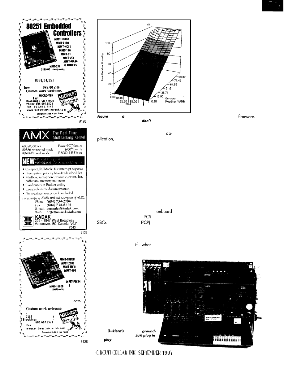
Midwest Micro-Tek is proud to offer
its newest line of controllers based
on the
architecture.
The 8031 comes in at a surprisingly
cost of
quantity).
MIDWEST
2308
Sixth Street
Products Ltd.
Y5
Embedded Systems Booth
low Cost Embedded
Controllers
7
MMT-31
MMT-251
OTHERS
S199.W
If you’re interested in getting the
most out of your project, put the
most into it. Call or Fax us for
plete data sheets and CPU options.
M I D W E S T M I C R O - T E K
East
Sixth Street
S D 5 7 0 0 6
Phone
6 0 5 . 6 9 2 . 5 1 1 2
True RH
Sensor RH
6 4 . 0 0 8 9 . 6 0
Temperature
76.80
2-Here’s sensor eye
view versus the real thing.
This graph needs a skier,
you think?
FLIGHT HARDWARE
To minimize the impact of a
multicard system, choose the embedded
CPU board wisely. It must be at home on a
bus, have the power to be used as the
development system, and be able to stand
alone when the mission requires it.
Although innovative in design and
there’s nothing exotic about the
sensor stock and CO, sensor. The embed-
ded hardware to monitor these devices
needn’t be complicated nor expensive.
However, you need to plan how the PGC
embedded system should be configured.
It would be simple (and wasteful) to
select a single-board solution that encom-
passes all of the common PC-compatible
peripheral components. This isspaceflight.
Power and mass must be conserved.
But, what if the PGC mission require-
ments change? What if Ethernet is needed
and our golden SBC doesn’t have
Ethernet capability? Or
(Seen any
lately with built-in
What if the
display type changes or we need a more
powerful CPU later? Can the SBC be ser-
viced, or is the whole thing chucked when
one part fails? What
if?
The only logical solution is to select an
embedded system that
can be built peripheral
by peripheral with mini-
mal impact to the mis-
sion software.
Almost every day,
I’m pushing and pulling
Photo
the VMA
support configuration.
and
with it.
X
peripheral cards out of desktops.
Why not apply that no-brain tech-
nology to the PGC project? I just
need a system that can be config-
ured on a backplane and stand
alone during the mission.
The card-by-card-on-a-back-
plane idea has some drawbacks.
First of all, if we really end up
flying the backplane, our embed-
ded footprint just got a bunch
bigger.
Next, power consumption will
be higher because of multiple
peripheral cards versus special-
ized silicon. Finally, troubleshoot-
ing now stretches across a
backplane and multiple
laden cards.
VMAX SBC 301
During normal operation, the PGC
doesn’t need a desktop display, keyboard,
or physical magnetic media to monitor the
plant environment. The actual flight con-
figuration must be a single-board solution.
At this point, the only other card required
for PGC software development is a display
card, assuming that our chosen CPU card
contains standard I/O ports and a way to
implement silicon disk emulators. Every-
body’s on a budget, so the CPU must be
inexpensive and powerful enough for our
application on the ground and in space.
Our PGC will fly with the Tempustech
VMAX SBC 301 single-board computer.
6 0
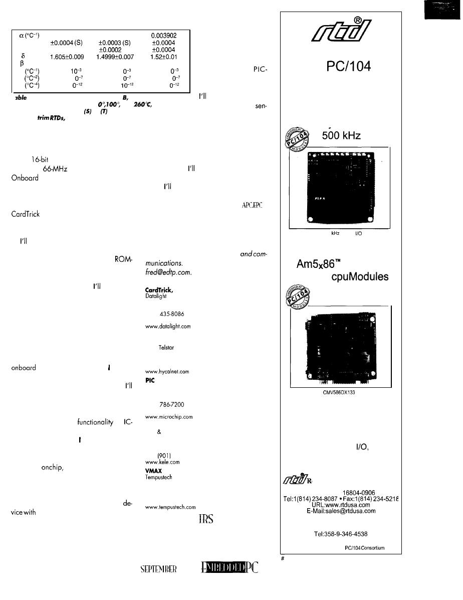
0.00375
0.00385
The output voltages
of the HyCal and Telaire
f0.0002 (T)
(T)
(“C)
sensors are perfect for
‘(“C)
0.16
0.10863
0.11
the A/D circuitry of the
A
3.81 x
3.908 x 1
3.96 x 1
+ 5 - V p o w e r e d
B
-6.02 x 1
5.775 x 1
-5.93 x 1
14000. There are eight
c
-6.0 x 1
-4.183 x
-4.3 x 1
analog inputsavailable.
l--This
equation uses constants
A, and C, which correlate
use three of them for
to resistance measurements at
and
respectively.
Uncertainties
followed by or are
associated
with standard
the HyCal humidity
sor, Telaire CO, sensor,
and
tight
respectively.
and RTD.
The SBC 301 is an industrial-grade CPU
card that’s 100% IBM/AT compatible.
The SBC 301 can operate stand alone
or in a
passive ISA-bus backplane
and has a
486SXLC processor.
peripherals include the standard
serial and parallel ports with floppy, IDE,
and 2.5 MB of solid-state disk support.
On the firmware front, Datalight’s
is included so the flash array
appears as a DOS disk. Photo 3 shows the
SBC 301 mounted in the backplane.
use the peripheral capability of the
SBC 301 to initiate the PGC software. And,
I’ll employ the services of Datalight’s
DOS and Microsoft’s Visual C++.
Since I have an Ethernet LAN in the
Circuit Cellar Florida Room,
include an
Ethernet connection to access data from the
other computers here.
Once the software is debugged and
loaded into solid-state disks, the SBC 301
will be on its own with the PGC.
WEIGHTLESS ANALOG-TO-DIGITAL
The SBC 301 does not contain any
A/D circuitry. Therefore, have to
supply an A/D front end.
Since the PGC needs may change,
include an analog front end with smarts.
tow parts count and minimum power con-
sumption are essential.
tow power and high
for
level embedded applications spells Micro-
chip PIC 14000. With it, can effect a super
low-fat A/D front end for this project.
The PIC 14000 is self-contained. Its os-
cillator is
and the only external
components needed are capacitors for the
A/D clock and power bypass.
The chip was designed for battery-moni-
toring applications. It’s a mixed-signal
internal temperature sensing, ana-
log comparators and a multiple-input ADC.
The dual-slope conversion technique of its
A/D subsystem supplies the accuracy we
need to take readings from the PGC.
GROUND EQUIPMENT PACKAGE
All the major pieces of the equipment
needed to monitor this PGC are in place.
Next time,
show the code and the
processes that make the PGC system func-
tional.
also explore different methods of
getting the data from the PIC 14000 using
the VMAX SBC 301 ‘s resources.
Fred Eady has over 20 years‘ experience
as a systems engineer. He has worked with
computers and communication systems
large and small, simple and complex. His
forte is embedded-systems design
Fred may be reached at
SOURCES
ROM-DOS
18810 59th Ave. NE
Arlington, WA 98223
(360)
Fax: (360) 435.0253
Survivor II Sensor
HyCal
Engineering
9650
Ave.
El Monte, CA 9 173 l-3004
(8
18) 444-4000
Fax: (8
18)
444-l 3 14
14000
Microchip Technology, Inc.
2355 W. Chandler Blvd.
Chandler, AZ 85224-6199
(602)
Fax: (602) 786.7277
Telaire 2001
V
KELE Assoc.
2975 Brother Blvd.
Bartlett, TN 38133
(901) 382-4300
Fax:
372-2531
SBC 30 1
295 Airport Rd.
Naples, FL 34104
(941) 643.2424
Fox: (94 1) 643-498 1
4
13 Very Useful
414 Moderately Useful
415 Not Useful
Sets The Pace
In
Data Acquisition
Scan 16 Channels...
Any Sequence...
Any Gain...
DM6420 500
Analog
Module
with Channel-Gain Table and FIFO
With Companion
133 MHz
PC/l 04
The
offers
versatile embedded functionality
Our PC/l 04 and ISA Bus
Product Lines Feature
Intelligent DAS Cards With
Embedded PC and DSP,
Analog and Digital
CPU,
Shared Memory, SVGA, PCMCIA,
CAN Bus and GPS Modules
eal Time Devices USA, Inc.
200 Innovation Boulevard
State College, PA
USA
RTD Scandinavia Oy
Helsinki, Finland
Fax: 358-9-346-4539
RTD is a founder of the
1997
129
61

TS
Cyliax
MC68030 Workstation
The Hardware
he
workstation project
started when our
ulty group realized that
there was no good 68k platform for
teaching assembly-language program-
ming. The traditional MC68000 ECB
from Motorola is no longer sold, and
the evaluation kits for the
weren’t exactly right for some
not to mention that they’re overpriced.
So, I suggested building our own teach-
ing platform.
We quickly decided this new system
had to be 68k based, since many text-
books use this processor as one of the
architecture examples. It was also
decided that it needed an ISA-compat-
ible expansion bus as well as a
code-based keyboard and some kind of
memory-based display interface.
Why ISA bus on a
system?
ISA bus is a very cost-effective sys-
tem, so it fit our limited budget. Since
most of the PCs in the department are
being continuously upgraded, I was
able to rescue many
VGA and
Ethernet cards from our surplus bins.
I also considered “cleaner” buses
such as
and VME, but could not
justify buying cards for these buses
when free cards were available.
In addition to the ISA-bus slots, I
added three custom
connec-
tors which provide access to the
62
Issue 86
September 1997
Circuit Cellar INK@
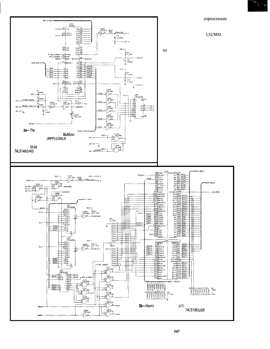
Figure
AT-compatible keyboard
interface is provided by the MC68901
tion Peripheral Controller
also
interfaces to the speaker and consolidates
some of the
ISA-bus interrupts. The
encodes the interrupt requests
info the interrupt /eve/ for the CPU.
fered CPU signals. So,
and fast memory can be added to this
system.
I also decided to use
TTL
components when possible. This way,
every part in the system is identifiable,
it should be easy for students to
infer what each component does from
standard datasheets.
There are two exceptions. One is a
PAL for decoding the bank selects for
the DRAM memory. Also, I used an
MC68901 MFP-a companion I/O chip
to the 68k line. It contains some timers,
parallel I/O, and the serial port used
for the keyboard interface.
Since this machine is essentially
built from scratch and I wanted to
follow the open methodology in hard-
ware and software, this meant writing
many components from scratch and
using freely available tools if the source
code was available. Later in the series,
I’ll describe the software-development
tools I used and the software I wrote
for this system.
By the way, the schematics, PCB
artwork, and program sources are
Figure
one of the ISA-bus
interfaces, which is replicated
several times on the motherboard. Also, the
provides the
decoding for the lower 2 Gb of addresses.
Circuit Cellar
Issue 66 September 1997
6 3

Address
Size
Description
8
8
16
16
8
8
32
32
64-Kb EPROM
MFP
illegal
ISA-bus
ISA-bus memory
ISA-bus
ISA-bus memory
repeat above
(O-7fffff)
DRAM
repeat DRAM
available via ftp, and you’re free to use
them for noncommercial purposes.
HARDWARE OVERVIEW
The system can be roughly divided
into four major groups-the CPU, ISA
bus, DRAM interfaces, and
I/O.
There’s only one
I/O device
on this system-the AT-compatible
keyboard interface.
I chose the MC68030 for my CPU. It
has a flexible bus interface and an inte-
grated MMU module. Since it has
dynamic bus sizing, it was easy to
provide interfaces for
ISA
bus, 32-bit DRAM, and
EPROM
and SRAM with minimal logic.
The processor asks for an object,
and the system responds with the port
size available. If the system port size is
smaller than the object to fetch, the
internal bus interface in the MC68030
automatically sequences and
the data to the appropriate place.
The MC68030 has two bus termina-
tion modes. The asynchronous termi-
nation mode, indicated by asserting a
combination of DSACKO and
is used when dynamic bus sizing is
required.
Its timing is also compatible to the
68k bus cycle. It is asynchronous be-
cause it assumes the data and
signals are asserted asynchronously
and have to be synchronized to the
CPU clock before processing.
The synchronous bus cycle, indicated
by asserting the STERM signal, shows
that the data and STERM are synchro-
nous to the processor clock and can be
processed without an extra synchroni-
zation cycle. Also, the STERM signal
indicates that the port size is 32 bits.
STERM allows the fastest possible bus
timing on the MC68030.
Table l--Since MC68030
processor has no instructions,
the ISA bus is broken up into four
address maps. Each causes a
different bus cycle to occur on the
ISA bus.
The MC68030 also
has a burst-mode opera-
tion to fill its cache
from page-mode
using an extension of the
bus-cycle mode. But since this system
is low end, this mode wasn’t imple-
mented. The data and instruction
caches also work well with the asyn-
chronous and nonburst-mode synchro-
nous-bus-cycle modes.
Given the flexible bus interface, the
MC68030 is easy to design with. I
ended up using asynchronous-bus-cycle
modes when addressing the ISA bus (8-
and
ports),
(8-bit
port), and
I/O resources
port). I used synchronous cycles for
speed when addressing the system’s
DRAM (32-bit port).
A
selector) decodes the
I/O, ISA bus, PROM, and SRAM address
space in the lower
address space.
The higher order address bit selects the
DRAM which, even though 4 Mb is
implemented, repeats in the 2-Gb
upper address space.
By placing the DRAM in the upper
address space, I was able to decode the
PROM in the lower memory where
the process fetches its reset vector and
initial stack pointer. Table 1 shows the
address map of the whole system.
A shift register generates differently
timed bus acknowledge signals. These
are selected using a 8: 1 selector-one
for each DSACKx signal-to generate
different wait states for each decoded
object. Hence, the ISA-bus I/O cycle
has to be longer than an SRAM access.
Another shift register generates a
bus-error exception if no bus acknow-
ledgement is received. This feature
implements a bus timeout for refer-
ences to illegal address ranges.
All that remains to interface to the
68030 is the interrupt interface and a
single-phase 1
clock, which is
derived from a TTL clock module.
Add these numbers up:
a ‘51 Compatible Micro
40 Bits of Digital I/O
8 Channels of
10 Bit A/D
Serial Ports IRS-232 or
2 Pulse Width Modulation Outputs
6 Capture/Compare Inputs
1 Real Time Clock
64K bytes Static RAM
+ UVPROM Socket
5 12 bytes of Serial EEPROM
1 Watchdog
1 Power Fail Interrupt
1 On-Board Power Regulation
adds up to real
That’s
our
popular
OEM
priced at just $299 in
single quantities. Not enough I/O?
There is an expansion bus, too!
Too much I/O? We’ll create a
version just for your needs, and
pass the savings on to you!
Development is easy, using our
Development
Board:
The
Development board
with ROM Monitor for $349.
Our popular 803
can now be
shipped with your favorite 8051
family processor. Models include
1
FA,
a n d
alternative to conventional ICE
products.
Load, single step,
interrogate,
disasm, execute to
breakpoint.
Total price for the
base unit with most pods is a low
$448. Call for brochure, or World
Wide Web at www.hte.com.
Equipment Corp.
S i n c e 1 9 8 3
566-l
Internet e-mail:
World Wide Web: www.hte.com
Circuit Cellar
INK@
Issue 86 September 1997
67
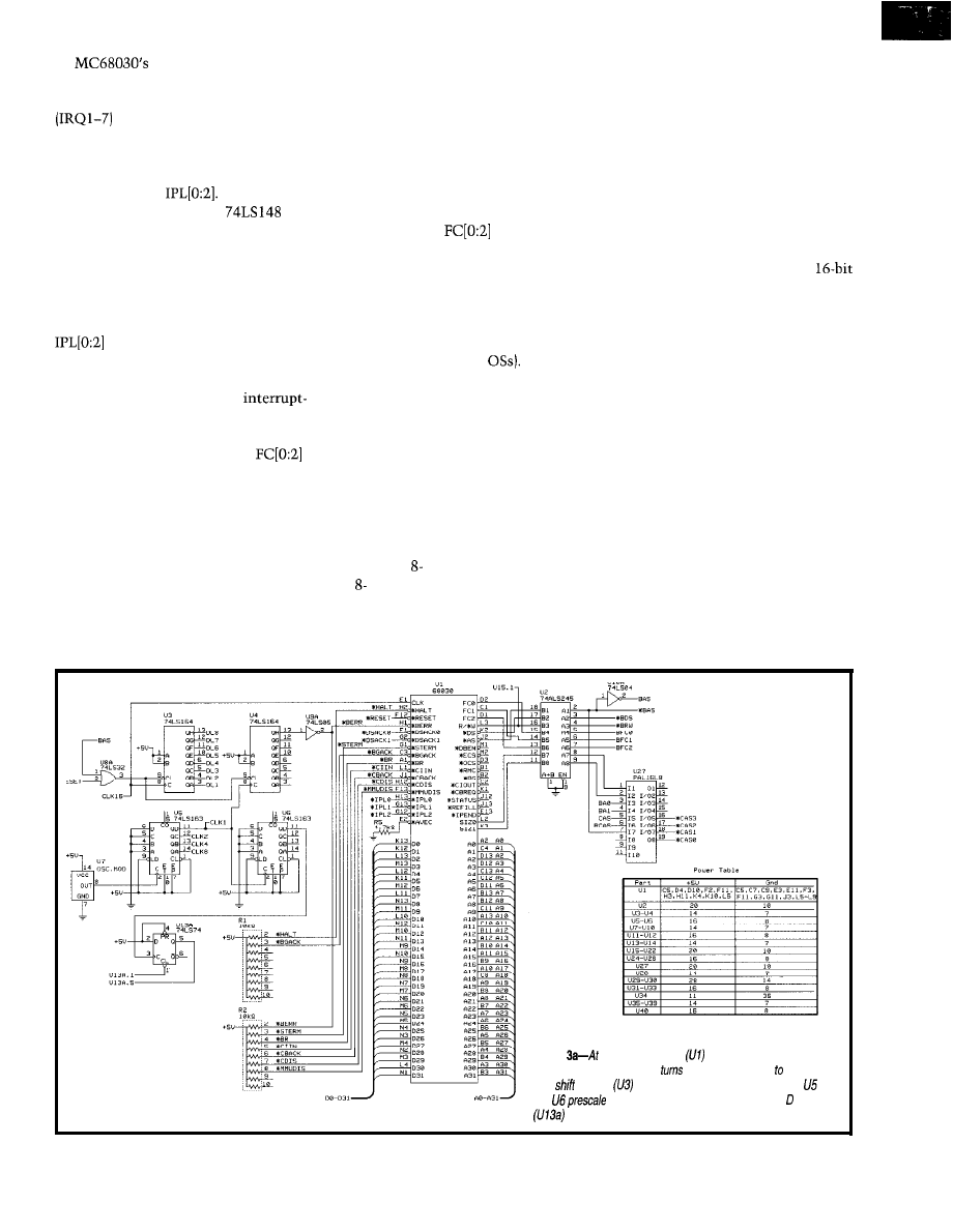
interrupt system is also
very flexible. (What did you expect?) It
uses multilevel priority-based interrupts
to request an interrupt. IRQ7
is the highest level and is not maskable.
The external interrupter asserts an
interrupt by encoding it into the three
interrupt signals
In this design, I used a
(8-l
priority encoder). Figure 2a shows the
interrupt circuitry and ISA-bus and
keyboard interfaces, while Figure 3a
shows the CPU.
Once the MC68030 sees the interrupt
request by noting that one or more of
are asserted, it responds to the
interrupt if the interrupt-request level
is higher than its current interrupt mask
or if it’s a level 7. It starts an
acknowledge cycle that resembles a
regular bus cycle, except that a special
bus cycle is indicated with the
function codes.
The interrupt-acknowledge cycle can
be terminated by a peripheral by supply-
ing an external interrupt vector and
asserting one of the bus termination
signals or by asserting AVEC. If the cycle
is terminated with AVEC, it uses a
processor what the source of the inter-
rupt was and how to handle it without
spending much time hunting down the
cause. In this design, it’s acceptable to
spend time polling devices for the inter-
rupt cause, especially since ISA-bus
devices don’t generate interrupt vectors.
Generating the autovector bus ter-
mination was easy. I simply decoded
the function code
to indicate
an interrupt-acknowledge cycle and
assert AVEC.
The integral MMU was an interest-
ing option, since it enables the use of
this platform in a serious OS-type class
project (e.g., virtual memory or memory
management in modern
In fact, I
developed a version of Minix that uses
the MMU, which the students can
dissect and explore. No external hard-
ware is needed to enable the use of
MMU functions on the MC68030.
The ISA-bus interface uses four of
the select lines to form the address
decoder to implement four address
maps. Each address map indicates one
of the possible ISA-bus cycles.
There are and 16-bit memories
and and 16-bit I/O accesses. The
An I/O cycle uses the IORD and IOWR
signals.
Figure 2b shows how the ISA-bus
interface is implemented. An ISA-bus
card can also extend a bus cycle by
asserting the signal IORDY. It was
necessary to implement this signal,
since many VGA cards stretch the
CPU bus cycle to deal with memory
contention to the video memory.
In addition to expanding the inter-
rupt system by implementing the
expansion interrupts, the MC68901
Multifunction Peripheral (MFP) handles
the AT-compatible keyboard interface.
The MFP expands the number of
interrupts by using six of the eight
general-purpose I/O pins as external
interrupt pins. They can be programmed
to be edge as well as level sensitive.
The MFP interrupt controller makes it
easy for software to find the interrupt
source by providing some registers that
indicate pending interrupts.
There are also facilities for masking
any of the interrupts and clearing pend-
ing interrupts. Table 2 shows the inter-
rupt map of this system. As you can
see, many of the interrupts are handled
predetermined internal interrupt vector.
memory accesses use the signals
by the MFP and are presented as a
A large real-time system may use
MEMRD and MEMWR to indicate a
single interrupt request at level 6 to
many interrupt vectors to tell the
memory read and write on the ISA bus.
the CPU.
Figure
first the MC68030
looks daunting, but after
looking at it more closely, it
out to be fair/y easy interface.
The
register
generates wait slates, while counters
and
the system clock for various uses. The flip-flop
implements the refresh request flag.
68
Issue
66 September 1997
Circuit Cellar INK@
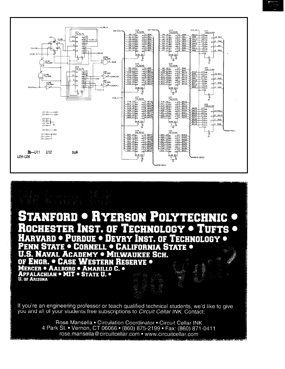
Figure
and
implement the
of the DRAM sequencer.
are the address multiplexer for the DRAM.
Circuit Cellar INK@
Issue 88 September 1997
6 9
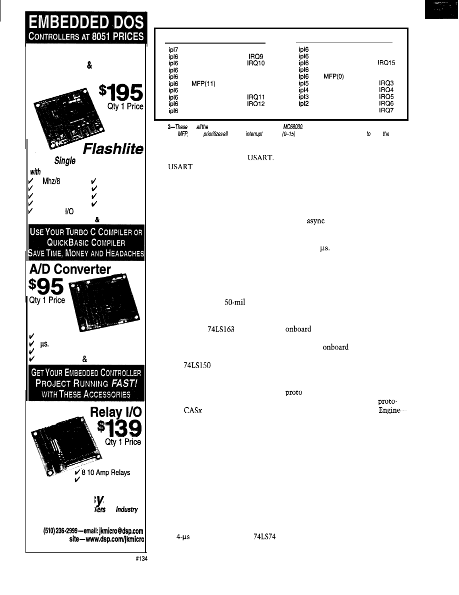
Jse Your PC Development Tools
No
M
ORE
C
RASH
B
URN
EPROM
Technology
DOS
Board Computer
512
k FLASH Memory disk drive
10
Mhz CPU 2 Timers
512 k bytes RAM
4 Interrupt Lines
512 k/256 k FLASH 8 Analog Inputs
2 Serial Ports
X-Modem File
24 Parallel Lines
Transfer
INCLUDES DOS Utilities
8 Channels, 12 Bits
6 Conversion Time
Clock/Calendar Option
Includes Drivers Apps.
8 Opto-Isolated Inputs
JK micros stems
Cost Effective Control for
TO ORDER (510) 2364151
FAX
Visit our WEB
1275 Yuba Ave., San Pablo, CA 94808
Level
Source
Function
Level
Source
Function
“break” button
NMI
MFP(4)
Timer D
MFP(15)
ISA-bus
MFP(3)
ISA-bus IRQ14
MFP(14)
ISA-bus
MFP(2)
ISA-bus
MFP(13)
Timer A (60 Hz)
MFP(l)
KBD data
MFP(12)
KBD receive
KBD clock
KBD error
direct
ISA-bus
MFP(8)
Timer B
direct
ISA-bus
MFP(7)
ISA-bus
direct
ISA-bus
MFP(6)
ISA-bus
direct
ISA-bus
MFP(5)
Timer C
ipll
direct
ISA-bus
Table
are
possible interrupt sources on the
Many of the interrupts are routed through the
MC68901
which
of
its
sources
and uses interrupt priority level 6 notify
CPU.
The MFP implements the keyboard
interface by using its internal
The
has a receive clock input
that enables a lx baud-rate clock, even
in asynchronous mode.
This feature is perfect for the AT
keyboard interface, since it uses a
clock signal to indicate when the serial
data needs to be sampled. The data
format for the AT keyboard scan codes
is 1 start bit, 8 data bits, even parity,
and 1 stop bit. Figure 2b shows how
the keyboard interfaces to the MFP.
To make the design more interest-
ing and useful for larger projects, I
added DRAM. A single 72-pin SIMM
module doesn’t take up much real
estate, but since it uses
staggered
pins, it’s a little harder to prototype
with. The DRAM interface port size is
32 bit and uses a
shift register
to sequence the CAS and RAS, which
are presented to the PLD for further
decoding.
I used
2: 1 muxes to multi-
plex the address bus. Since the 68030
needs to be able to write byte data to
memory, I implemented a bank decoder
in the PLD to assert the correct combi-
nation of
selects and satisfy any
possible data-transfer situation.
Figure 3b shows how the DRAM
subsystem interfaces with the CPU.
Table 3 shows the truth table for the
byte-selection logic implemented by
the PLD.
Of course, you have to refresh all
the rows in the DRAM once every
2 ms. This task is accomplished by
dividing the system clock down to
4 us. That gives one total refresh cycle
in 2.048 ms, which I thought was close
enough.
The
clock edge triggers a
flip-flop to indicate a pending refresh
request. Once the current CPU cycle
finishes, a separate shift register will
time a CAS before RAS refresh cycle
and present the PLD with an RCAS
signal to indicate that this is a refresh
cycle, while the next CPU is blocked.
Once the refresh cycle is done, the
refresh-request flip-flop is cleared us-
ing an
clear input. It’s unlikely
that a refresh request is skipped, since
a CPU cycle and one refresh cycle take
less than 4
I also considered that someday I
might want to add a floating-point
processor to the system, but I didn’t
want to clutter the design. So, I added
a CPU bus instead.
This bus essentially brings all the
CPU pins into a 96-pin DIN connector.
There’s also a signal that inhibits the
decoder and enables the CPU
card to decode address spaces which
shadow the
resources.
MOTHERBOARD DESIGN
The wire-wrap version of the mother-
board was done on a special wire-wrap
board we developed at IUCS for
chip testing and system-level
typing. This board-the Logic
contains a parallel port interface that
enables a PC to set and read 128 bits of
I/O, program timers, and so forth.
For this project, we didn’t use this
interface and build the system as a
stand-alone prototype. I actually created
two wire-wrap prototypes.
The first was a 68020 system that
included a prototype ISA-bus interface
to demonstrate the feasibility of writ-
ing software that could interface with
PC peripherals (e.g., the VGA graphics
card and floppy interface).
The 68020 system was short-lived,
since it only implemented 8-bit devices
70
Issue 88 September 1887
Circuit Cellar INK@
72
issue 86 September 1997
Circuit Cellar
INK@
PORT I/O
$ 9 0 . 0 0
4
Serial Ports, 2 Bi-Parallel Ports,
2 Drive IDE, 2 Floppy Interface,
16 Bit Standard, 8 Bit Adaptable,
Low Profile
Full Cable Set
486
SINGLE CARD
COMPUTER
$335”
Up to
drive
Compact-XT height card size
Industry Standard PC-l 04 port
L2 cache to
to
Dual
connectors
All Tempustech
products are
PC Bus Compatible. Made in the
U.S.A., 30 Day Money Back Guarantee
*Qty 1, Qty breaks start at 5 pieces.
TEMPUSTECH, INC.
TEL: (800)
FAX: (941) 643-4981
E-Mail:
I-Net:
Fax for
fast response!
295 Airport Road
Naples, FL 34104
a d r l
sizl
c a s 3 c a s 2
0
0
0
1 0 0
1
1 0
1 0
0
1
0
1
0
1
1
11 1
0
1
0
1
0
1
1 0
1
Table
table for the byte-selection circuitry
for the DRAM interface is
in the
For
each
combination of address location and
size
appropriate CAS
selects fo DRAM
be
generafed.
and had no DRAM. After testing some
of my assumptions about the ISA-bus
interface on this system, I proceeded to
design and build a wire-wrap prototype
of a 68030 system.
I documented the design as I went
along and was able to design in steps
that made the design more modular
and kept my confidence high that I
could get everything to work.
Contrast this approach to designing
the whole system and then building a
wire-wrap prototype only to discover
that many things you assumed would
work didn’t. It’s much easier to debug
an incremental design.
Once the design was working and
verified to match the documentation, I
passed it on for PCB layout. The board
was laid out to ensure that all the
mounting holes, ISA-bus slots, and
power connectors could fit in a stan-
dard baby-AT case.
While this choice enables us to use
ultra-cheap PC cases with power sup-
plies, I think it makes for an unattrac-
tive machine. It looks just like a PC!
This situation has, of course, evoked
many funny situations when an unsus-
pecting user gets a totally foreign
monitor prompt instead of the familiar
Windows look.
After the PCB layout was complete,
we spent a nervous two weeks waiting
for the first samples to come back
from the board house. We distracted
ourselves by working out the logistics
of ordering components to build 20 of
these systems and by putting some
finishing touches on the software.
The first board worked, although it
had a few erratas that we incorporated
in the final layout. To date, the final
layout has only had to have one errata
in three years of service.
HARDWARE WRAPUP
Even though the design is fairly
complex, we ended up with 20 out of
20 working systems. This process
shows that wire-wrap prototype designs
running at 16 MHz are no major chal-
lenge as long as you use well-designed
prototype boards that have a ground
plane.
Next month, I’ll talk about the
monitor software and how it boots, as
well as some of the issues involved
with programming ISA-bus peripherals
in a 68k.
q
Cyliax is a research engineer in
the Analog VLSI and Robotics Lab
and teaches hardware design in the
computer-science department at Indi-
ana University. He also does software
and hardware development with Deri-
vation Systems, a San Diego-based
formal-synthesis company. You may
reach
at
Schematics and PCB artwork for
this system can be found at
L.C. Eggbrecht, Interfacing to the
IBM Personal Computer, SAMS,
IN, 1990.
Motorola, MC68030 Enhanced
bit Microprocessor User’s
Manual, Phoenix, AZ, 1990.
Motorola, MC68901 Multi-Function
Peripheral, Phoenix, AZ, 1988.
Motorola, Motorola Memory
Databook, Phoenix, AZ, 1989.
E.
ISA EISA: Theory and
Operation, Annabooks, San Diego,
CA, 1992.
416
Very Useful
417 Moderately Useful
418 Not Useful
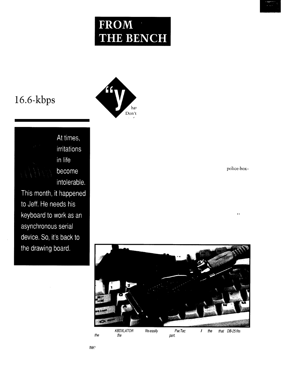
KBDXLATOR
Jeff Bachiochi
A Cure for the
odd
Parity Blues
eah, Dad, we’ll
have plenty of room.
Don’t forget, you took
most of my stuff home
last weekend.”
Why should I worry? Dan’s a college
graduate now. He should have moving
in and out of dorm rooms down pat.
“We’ll be fine,” I thought. “With
the Honda and the Caravan, there’ll be
room for the nine of us.”
We made a dozen trips to the Honda.
With the rear seat folded flat, there was
room for the oddest shaped items. The
back seat filled quickly, then the trunk.
We pushed stuff into the smallest spots.
After the passenger seat filled, we
stopped. Someone had to drive home.
“We’re not gonna get any more in
here. Let’s go. It’s almost time for
commencement.”
“All packed?” my wife asked when
we returned.
“Not exactly. Dan seems to have
underestimated a wee bit. We’ll have
to
put a few things in the van after the
ceremony.”
Commencement exercises were
filled with the usual abundance of
laughter and tears. And suddenly, four
years of work were over.
“Everybody grab something. We’re
not coming back,” Dan exclaimed as
we left his apartment. We looked like
an African safari. A single file of bodies,
each carrying a staggering burden.
I think Dan carried the biggest bur-
den of all. I saw it in his eyes as he
shut the door for the last time.
“Where’s all this gonna go?.” was
everyone’s question. But, I had a secret
weapon. Bungees.
The table and all the luggage fit on
the van’s roof rack, thanks to the bun-
gees. After spinning the web of elastic
thread, it was a simple engineering task
to fit the remaining objects in.
Each person was packed into their
seat. My parents were in the center.
Mom was pinned in by a folding chair,
while Dads feet were on the cooler.
Our Caravan reminded me of Dr.
Who’s tardis-a wonderful
shaped time machine with an inside
larger than its outside.
The whole packing process reminds
me of trying to fit more circuitry onto
ever-shrinking real estate. It’s the facet
of engineering I find most challenging.
High on the list is making use of
items that are already available..
LIKE THE KEYBOARD
The most widely used input device
connected to the PC today was, is, and
Photo 1 --The
circuitry
info a small
enclosure. like fact
a
info
package and whole thing plugs right info a serial
74
Issue 86
September 1997
Circuit Cellar
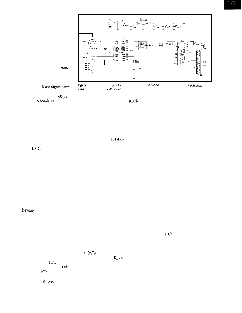
will be (at least in the near future) the
keyboard. Although it has gone through
a few redesigns, it remains pretty much
the same as the day the first PC rolled
off the assembly line.
Although the PC has always had
serial ports, the PC keyboard wasn’t
designed as an asynchronous serial
device. Considering the price of a key-
board, it could be cost effective in
many projects requiring ASCII input.
The PC/AT keyboard uses a
signal clocked synchronous serial
format. The keyboard supplies the
clock for the 1 l-bit data transmission.
Eight data bits of
bit-first format are surrounded by start,
odd parity, and stop bits. The
bit
time provides a
data rate
(not exactly one of the most common).
Because the keyboard samples the
clock and data lines, its transmissions
can be halted while it receives data from
the host. In this case, it still provides
the synchronous clock for the transfer.
The host can command the keyboard
to restart the power-on self test, resend
the last data byte, and enable or dis-
able the three
(num, caps, and
scroll lock) in the keyboard’s enclosure.
Actually, the keyboard doesn’t need
any feedback from the host to operate.
It’s happy just outputting key make
and break codes.
FOUR KEYS SHORT OF A PIANO
Unlike the normal serial terminal
where you press the letter A and receive
the universal ASCII code for the letter
A, the PC/AT keyboard outputs a value
which seems to have no logical sense.
Each
(or switch position) has
a number associated with it in an al-
most natural left-to-right top-to-bottom
format. Each numbered position has a
different number associated with it
called a make code (i.e., the value sent
when a key is pressed). This number
has no relation to either the position
or the ASCII code.
Think of it as a secret code. When
the A key, position 3 1 (decimal), is
pressed, a make code of
is sent to
the host. When A is released, an
is
sent, followed by a
code indicat-
ing a break code.
So as you see, the
PC/AT
keyboard is really stupid. It doesn’t
l--Not much external
is needed around the
processor.
Configuration
be
to select baud rate
the serial output.
know an A from an a, and it doesn’t
know the three-fingered salute
Alt-Del). It’s the system that remembers
which keys are held down and adjusts
the translation accordingly.
It was nasty when the AT came onto
the market. The AT’s keyboard format
wasn’t compatible with that of the XT.
Now, XT keyboards are all but extinct.
When the newer
AT key-
boards came on the scene, they at least
retained a mode emulating the 84-key
make-/break-code format. However,
they do reset into a different mode and
must receive a change-of-mode com-
mand to emulate their older brother.
FORMAT TRANSLATOR
To correct this engineering faux pas,
you must be able to read keyboard trans-
missions. Since they’re synchronous
and data is valid during clock low, I’ll
use a falling-edge interrupt.
When a falling edge triggers an
external interrupt, the interrupt routine
grabs the data line’s state and reverts it
to the in-line code.
The first in-line routine,
K-START,
checks for a proper start bit (i.e., a 0). In
addition, the parity flag is preloaded
with a 1 and the timer is set so an
overflow will occur after -1 ms.
The next eight bits route through
the
routine, which rotates them
into the byte-variable
L.
If any of
the data bit values are 1, the parity flag
is complemented, which keeps a run-
ning correction to the parity flag.
Next, the odd-parity routine checks
whether the computed parity flag and
the received bit are the same. Finally,
the stop-bit routine checks to see that
a proper stop bit (i.e., a 1) is received.
If an error occurs with any of the
checks along the way or if the timer
overflows, the data is dumped and con-
trol jumps back, looking for another
keyboard start bit. Otherwise, the data
byte is carried into the second half of
the in-line code. So much for grabbing
the keyboard’s transmissions.
To prevent the keyboard from poten-
tially transmitting more data, I turn the
CLK input line into an output and drive
it low. Now, I decide what to do with
the code received from the keyboard.
Since this key code is
not
the ASCII
equivalent to the key pressed, we have
a chance to do some character transla-
tion. A few codes need trapping before
they’re translated. Most are responses
to commands sent to the keyboard.
Once they are trapped, the program
flow is steered around the UART rou-
tine so no output is produced.
The next codes trapped also produce
no output, but they do have important
functions. They set flags to help navi-
gate the program flow toward the proper
tables (described below). They are the
break code
and the shift, control,
and alternate key codes.
NO ROOM AT THE INN
A table that can hold all the possible
characters sent by the keyboard would
require 255 entries. Some characters
require multiple keys to be pressed
simultaneously (e.g., shift + m = M).
The characters can be broken down
into four groups-unshifted, shifted,
control, and alternate.
Circuit Cellar INK@
Issue 88 September 1997
7 5

C
0
IO N
PAINFULLY BRIGHT RED LED
2500
to
4000 mcd 20 ma. These
T
(5 mm diameter) red
are
significantly brighter than conventional
At close range, they are painful
to look at. They are great for attention getting
displays that can be seen from a distance.
1000 for $400.00
Twist-on co-ax connector for
cable.
500 for
$50.00
l
1000 for $70.00
0.7” dia. X 1.7” long. Right angle PC
or solder leads on 0.25” centers.
CAT# PPC-410
10 for $18.50
l
200 for $320.00
C.P. CLARE /Theta J #
Compact,
compatible, opti-
cally isolated solid state relay for
loads up to 5 amps 240
0.8” x 0.82” x 0.56” high epoxy bloc
with a 1.4” long metal mounting flange. 1.19”
mounting centers. 0.062” dia. x 0.175” high
pins. Input: 4 8 Vdc
SSRLY-2405
continental U S A $5.00 per order. All others
AK.
HI. PR
Canada
pay full shipping. All orders delivered
de
sales tax.
NO COD Prices
With 255 possibilities for each group,
that’s 1000 table entries. The
only has room for 1 KB of code, so this
many table entries leaves nothing left.
Of the total 255 possible key codes
(excluding the ones trapped), none are
above 7Fh. So, the high bit is cleared,
and they now fit into a table of only 128
for each group. The four tables reduce
to 0.5 KB, and there’s still 0.5 KB left
for the executable code.
To track the two shift keys, caps
lock, control, and alternate combina-
tions, the trapped codes set or clear flags
based on whether or not the break flag
is set or cleared.
For the caps-lock key code, the shift
flag bit is complemented since it toggles
and doesn’t have to be held down. The
other flags (i.e., shift, control, and alter-
nate) are set while the key is pressed.
Or, they are reset if the previous key
code was an
and a break flag was
set, indicating that a key was released.
All other key codes are passed on to
the in-line UART routine.
The code looks at the control, alter-
nate, and shift flags to determine which
of the four character-translation tables
to use. The tables can be filled with any
constants you want, which allows for
ASCII output as well as customized key
translation.
I chose to shift the control table
translations for A-Z down by 40h to
output the ASCII control codes
In the alternate table, translations
for O-7Fh are shifted up 80h to output
8-bit extended ASCII codes covering
the graphic-drawing characters.
The shift table translates key codes
into uppercase or upper-row ASCII
characters, while the unshifted table
translates them into lowercase or
row ASCII characters.
Untranslatable characters (e.g.,
F12) send out null characters. But, they
can send out any ASCII character you
put in their translation-table positions.
Once the key code is translated into
a character code, the byte is ready to
send via a UART. The
doesn’t
have a hardware UART, so the asyn-
chronous output has to be bit banged.
To ensure accurate bit timing for the
asynchronous serial transmissions, the
timer is set to produce an interrupt for
each bit. The in-line code uses three
500
Figure
fop trace
shows PCA J
clock
and second is the
trace
shows
serial
Notice
clock line is held low prevent more
until
has finished ifs transmission.
routines--U-START,
and
STOP-to set the data bit to be output.
The timer-overflow interrupt routine
outputs the data to the port pin. A
configuration input bit lets the serial
output be normal or inverted, depend-
ing on whether true RS-232 levels are
needed. I added an external MAX232
level shifter (see Figure but you can
cheat and use a straight TTL interface.
Once the character is sent out the
(software) UART, the keyboard is again
enabled (by returning the CLK to an
input configuration] and the code jumps
back to the top, and is ready to grab the
next keyboard transmission. Figure 2
shows the results of a scope trace of
the keyboard’s transmission.
ROOM ON THE INSIDE
Unfortunately, the processor in most
PC/AT keyboards isn’t low power
(probably because they were designed
to run off the PC’s power supply).
The interface could steal enough
power off a serial port to operate. But
since the keyboard needs its own power,
I might as well power the whole mess
off a wall-wart supply.
I chose the
because, while it
doesn’t have a hardware UART, it does
have a few interrupt sources that make
coding easier.
Also as many of you know, I’m a
crash-and-burn kind of guy. The fact
that the
is reprogrammable
keeps me from filling my wastebasket
with dumb mistakes.
76
Issue
66
September 1997
Circuit Cellar INK@
Although I initially planned to fit
this circuit into the empty corner of a
PC/AT keyboard and eliminate the cord,
I thought it would be simpler to put
the circuitry on a cord and keep the
keyboard standard, as Photo 1 shows.
makes a new line of plastic
cases with a variety of molded ends. A
case with a DB-25 cutout at one end and
an
1
at the other works well. Oppo-
site the DB-25, I added a hole for the
power supply and one for an LED, while
the keyboard jack fits into the
l’s
square hole.
The next time I need a serial input
device, I won’t have to drag over a
whole PC. Now, I can just whip out
the KBDXLATOR.
Too bad it doesn’t move furniture.
q
Bachiochi (pronounced
AH-key”) is an electrical engineer on
Circuit Cellar INK’s engineering
staff.
His background includes product design
and manufacturing. He may be reached
at
Microchip Technology, Inc.
2355 W. Chandler Blvd.
Chandler, AZ 85224-6199
(602)
Fax: (602) 786-7277
www.microchip.com
Digi-Key Corp.
701 Brooks Ave. S
Thief Falls, MN 56701-0677
(218) 681-6674
Fax: (218) 681-3380
CNL-X-X enclosure
8425 Executive Ave.
Philadelphia, PA 19 153-3893
(215) 3658400
Fax: (215) 365-4420
MAX232
Maxim Integrated Products
120 San Gabriel Dr.
Sunnyvale, CA 94086
(408) 737-7600
Fax: (408) 737-7194
419 Very Useful
420 Moderately Useful
421 Not Useful
“We’re impressed by the
documentation and the readability
You Should Choose Embedded BIOS, Too
of code. Ryan
BIOS, DOS, Flash
Disk With One Low Royalty
“We are
pleased
with the
General Software BIOS and look
Instant Boot, Console Redirection, Much More
forward to working with you to bring
our product
to market. R.
Expert Support with Guaranteed Response Time
Embedded BIOS is well-structured
We Work Closely With
AMD, Intel,
and documented, and technical
Deliver you a Proven, Tested, Feature-Packed BIOS
support at General
is
Millions of Units Already Licensed
sure we made the right
decision to buy our BIOS from
BIOS Adaptation Kit
Includes:
General
Complete Source Code
“Embedded BIOS is
Binary Configuration Program
embedded PC designs.
You were absolutely right.
Quick Start + Over 600 Pages of Printed Documentation
G e n e r a l S o f t w a r e , I n c .
3 2 0
A v e .
S u i t e
4 0 0
W A 9 8 0 0 4
T e l : 2 0 6 . 4 5 4 . 5 7 5 5 . F a x : 2 0 6 . 4 5 4 . 5 7 4 4 . S o l e s :
E-Mail:
The Q-Bit
is:
A high speed
baud) multidrop
master/ slave RS-485 network
Flexible- Compatible with your
microcontrollers
Robust
CRC and sequence
number error checking
Low microcontroller resource
requirements (uses your chip’s built-in serial
Simple-to-use C and assembly
language software libraries, with demonstration
programs
Complete- Includes network software,
network monitor, and RS-485 hardware
is an asynchronous
adaptation of IEEE 1118
55
Temple
Place
l
Boston, MA 02111-1300
l
Ph 617.350.7550
l
Fx 617.350.7552
Circuit Cellar INK@
Issue 86 September 1997
7 7
Tom Cantrell
Radio Chip
0
he micro busi-
ness seems to go in
cycles, with focus
shifting between major
applications arenas such as control,
computation, and communications.
Notwithstanding Apple 11s and
boxes, for most of its preteen years, the
micro mainly served control applica-
tions. It wasn’t until the appearance of
the IBM PC-almost ten years after
the 4004 was introduced-that com-
puting became a major micro market.
Computing has remained king for
the last decade or so, and what a Golden
Age it’s been. The micro has evolved
from yesterday’s toy to deliver the
power of yesterday’s mainframe onto
your desk or even into your pocket.
Now, computing is entering an era
of less revolutionary growth rates. All
of the easy and many of the hard prob-
lems have been solved. Those truly
tough ones that remain-everything
from the quest for instruction-level
parallelism to readable documenta-
tion-won’t succumb easily.
Fortunately, just as computing is
getting a little ho-hum, communication
is stepping to the fore. Nowadays,
getting gadgets to talk to each other is
all the rage. Of course, sometimes it
isn’t clear whether meaningful dis-
course will result, but establishing the
connection and seeing what transpires
is the only way to find out.
When it comes to communication,
there’s progress on both the wired and
wireless fronts. Frankly, I find the latter
much more interesting. As I contem-
plate my own miles of spaghetti-cable
inventory, I’ll be glad when they dis-
pense with wires altogether.
To get a sense of which way the
wireless wind is blowing, let’s check
out the
Engine from Mi-
cron Communications (a subsidiary of
well-known DRAM supplier Micron
Technology). Though specifically tar-
geting the ID-tag niche, a look inside
gives a glimpse of what the wireless
future might hold.
Before hitting the datasheets, how-
ever, let’s consider some of the market
and technology forces at work.
TAG ALONG
RF (radio frequency) ID isn’t a new
concept, having been around for almost
50 years. Probably the most familiar
incarnation is the antishoplifting tag
familiar to most shoppers. If the tag
isn’t removed by the clerk, a gateway
positioned at the exit sounds the alarm
when the absconder passes it.
Other forms of wireless (e.g., bar
codes, IR) and semiwireless (e.g., Dal-
las Semiconductor Touch Memory)
asset-control and -tracking schemes
exist. However, they presume a non-
hostile user and wouldn’t be suitable
for security applications. The ability of
RF to look inside a pocket, briefcase,
or box is a big advantage.
Consider reports that 100,000s of
laptops are stolen each year, most from
companies and universities. In many
situations, at least those where ingress
and egress is controlled (i.e., a gateway),
an RF-ID tag buried inside might well
deter the light-fingered.
Essentially, the tag listens for a
query from an interrogator positioned
at the gateway and responds with ID
info when asked. Typically, range is
limited to a few feet or less.
This feature not only reduces power
and improves noise immunity, but it
also confines activity to the proximity
of the gateway. Obviously, the
shoplifting system is more annoying
than helpful if it can’t discriminate
between someone walking near and
someone walking out the door.
78
Issue
66 September 1997
Circuit Cellar INK@
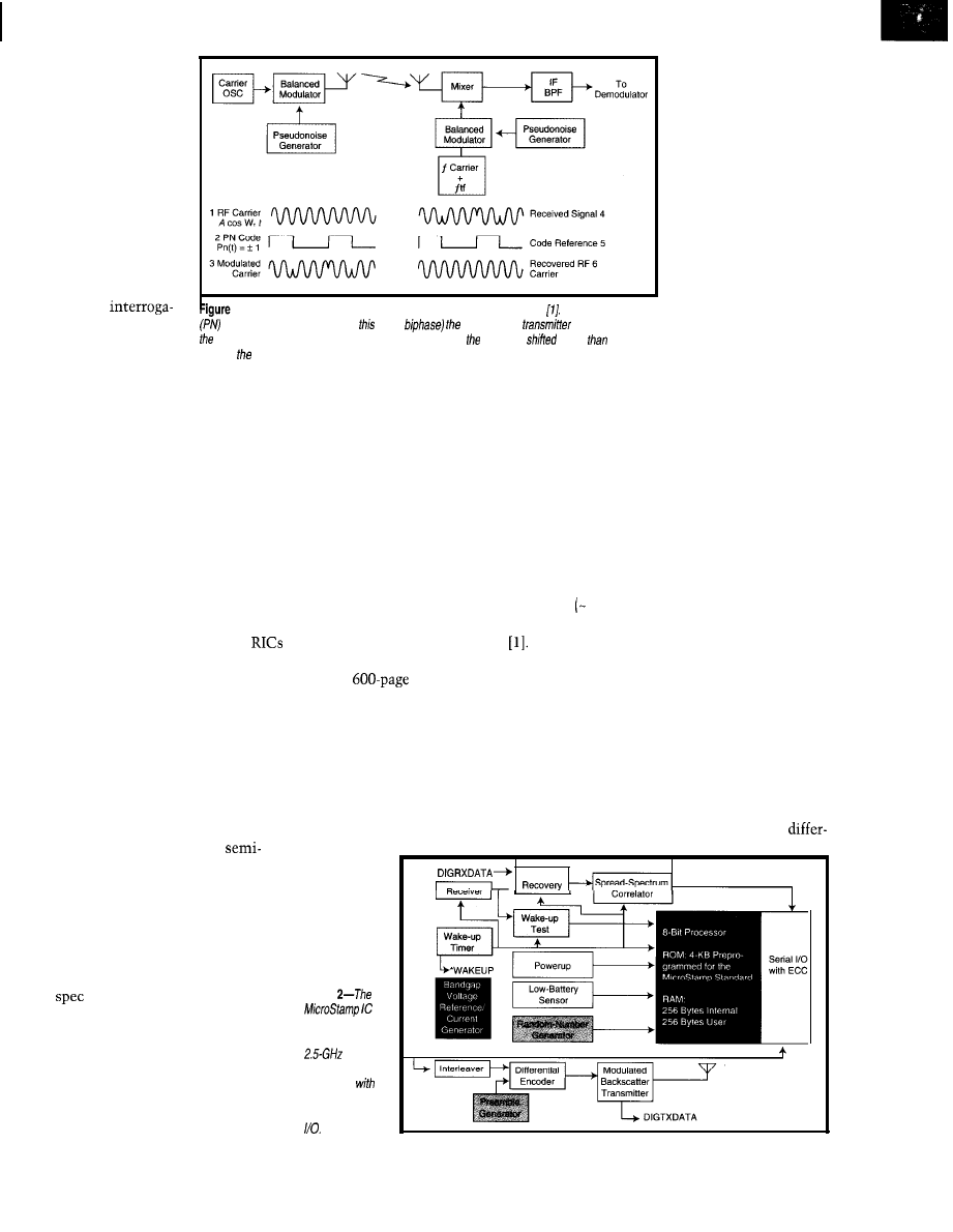
Tag technology is
primarily classified as
active or passive-a
terminology that’s a
little confusing. Usu-
ally, it refers to whether
or not the tag requires a
power source (i.e., a
battery) or derives
power from the inter-
rogator’s transmission.
It can also refer to
whether the return
[from tag to
1 --Here are the basics of a direct-sequence spread-spectrum system
A
pseudonoise
tor) radio link requires
code sequence modulates (in
case,
carrier at the
and recovers if at
emission by the tag or
receiver. A frequency-hopping system is similar, except carrier is
rather
modu-
uses a reflective tech-
lated by code.
nique. A simple analogy for the latter,
known as backscatter modulation, is
signaling using a mirror
(tag) to
reflect
the sun (interrogator).
The cheap ($3) passive tags down at
the mall are being joined by a new
generation of more powerful units
with more intelligence and range.
Rather than just a read-only ID num-
ber, these units feature larger read/
write memories and, thanks to the
FCC release of unlicensed bands, higher
frequency operation for better reliabil-
ity and throughput.
Such units, which Micron calls
(Remote Intelligent Communication)
extend the RF-ID concept into new
applications. For instance, fleet (e.g.,
bus, taxi, truck, etc.) applications can
combine an RIC with GPS and a data
logger for pervasive, yet unobtrusive,
tracking. When vehicles return to the
depot, a complete dump of when and
where they’ve been is left at the gate
as they drive through.
Another idea is automated
custom manufacturing and distribution.
Say you phone in an order for a PC
with a certain configuration and selec-
tion of add-ons. A tag can be stuck on
the motherboard to accompany your
system down a production line.
At each stage, an interrogator queries
the
and presents any work order
to the assembler, whether human or
robotic. The tag accompanies your PC
into the box, out the door, onto the
truck, and off the truck, thereby secur-
ing against “shrinkage” and eliminat-
ing finger pointing when the inevitable
mixup occurs.
THE LOW-PRICE SPREAD
Like many technologies we take for
granted in daily civilian life, spread-
spectrum communications has its
genesis in conflict-WWII, the Cold
War, and even the space race. We’ve
sure come a long way from a 1947
patent for “Secret Communications”
to the average Joe’s cordless phone.
I’m certainly no expert on the sub-
ject, which fortunately suffers no short-
age of those who are. One reference I
find both rigorous yet intelligible is
Dixon’s
Spread Spectrum Systems
with Commercial Applications
Needless to say, I won’t be dissect-
ing the
tome in detail. But,
it’s worth hitting a few of the high
points for those who aren’t familiar
with the subject.
Actually, many of you probably are
but just don’t know it. For instance,
most computer enthusiasts are familiar
with the concept of ECC (Error Correct-
ing Codes), in which extra check bits
Figure
combines a
complete
spread-
spectrum radio
subsystem
an d-bit micro,
RAM, and serial
are packed along with
the data.
Or, how about the
concept of multidrop
communications, in
which addressing al-
lows multiple units to
share a single medium?
Or, consider encryption
systems that rely on a
key to decode data.
Notice that in all
cases, extra bandwidth
in the channel (beyond
that required for data
alone) is given away in
the interest of boosting
the reliability, addressability, and
security of transmission.
Turns out, there’s a lot of similarity
with the historically analog spread-
spectrum concept. In comm-speak, the
difference between the bandwidth
available in the channel and that re-
quired for data is known as the “process
gain.” It can be traded off for more
robustness and security.
Of course, FM radios are spread
spectrum in that the radio frequency
100 MHz) far exceeds the data band-
width
(-1
MHz for CD-quality audio).
However, use of the spread-spectrum
moniker is usually reserved for systems
in which some signal (other than the
data) overtly spreads the transmission.
Two of the most popular forms are
direct sequence and frequency hopping.
They’re similar in that both require a
code sequence that’s known a priori by
both transmitter and receiver.
In a frequency-hopping system, the
code orders the shifting between
Clock/Chips
Circuit Cellar INK@
Issue 86 September 1997
79
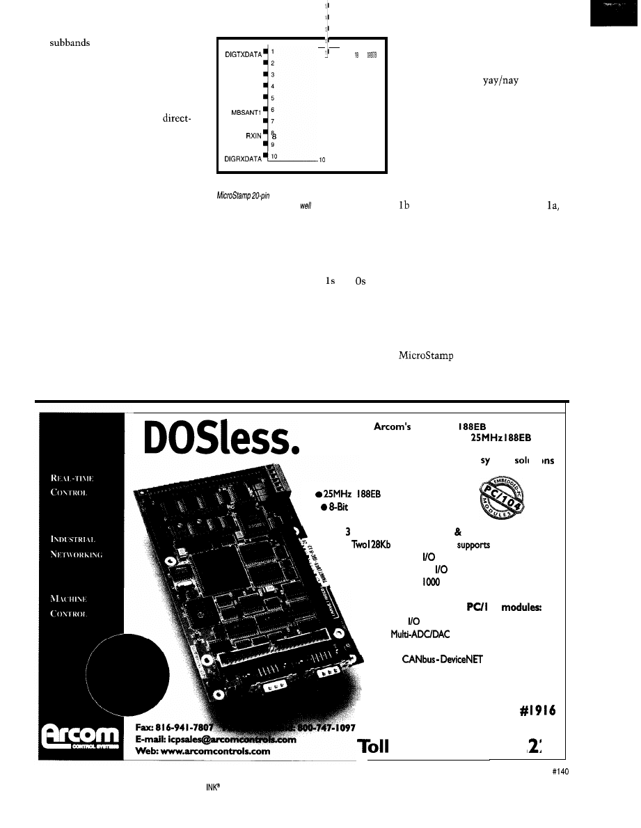
em
of the entire bandwidth
available. This type of system is best
for spy-versus-spy stuff since such
frequency-agile gear is quite difficult
to eavesdrop on or jam.
For less expensive (or paranoid)
commercial applications, the
sequence approach of Figure
1
(repro-
duced from Dixon) is most popular.
A pseudonoise (PN) code sequence
modulates the signal at the transmitter,
and the receiver looks for the same
code. The receiver passes those trans-
missions that match the local code
reference through while spreading
everything else across the entire chan-
nel bandwidth, allowing the final Inter-
mediate Frequency (IF-the frequency
at which the code is clocked) filter to
mask unwanted interference.
The PN codes themselves are quite
interesting. As the name implies, they
exhibit a random noise-like nature that
spreads the signal evenly across the
bandwidth and stymies surveillance to
the degree the code is kept secure.
Of particular note are code sequences
derived from feedback-connected shift
,
“WAKEUP
2
VDD
3
MBSANT3
4
MBSANTP
5
RXANT
,
VSSA
9
20 19 18 17 16 15 14 13 12 11vss vss vss vss DPCLK DPDATA NC
Figure 3-h addition to direct
antenna connections,
the
SO/C package supports digital
transmit and receive ports as
as a bidirectional
clock serial port.
registers (an old trick at the core of
most random-number generators). The
key characteristic uniting two different,
but same length, sequences is that the
statistical distribution of and and
their run lengths is the same, though
position in the sequence differs.
The most interesting facet of these
sequences is the minimal correlation
with their phase-shifted equivalents.
Table
la
(also from Dixon) compares a
seven-code (i.e., three-stage shifter)
sequence with all possible phase shifts
of itself by subtracting the number of
disagreements (D) from agreements (A)
at each bit position.
Notice the clear
distinction
between in- and out-of-phase compari-
sons. Minimizing such autocorrelation
between a code and itself helps to over-
come multipath and self-generated
interference.
Minimizing cross-correlation be-
tween different codes is, of course,
important when multiple transmitters
and receivers share proximity. Table
shows a comparison similar to
except using a different code.
Notice that the results are less clear
and might cause false sync or other
disruptions. If you want your applica-
tions to exploit coding for multidrop
addressing, take great care to choose
codes with minimal cross-correlation.
ON THE AIR
Oops, halfway through my space
and haven’t even talked about the
yet. Hopefully, the back-
ground info will help keep the explana-
tion short and sweet.
.?
TARGET
processor board
features Intel’s fastest
CPU
for ultimate, cost effective embedded
stem
i
Embedded CPU
PC/ IO4 Interface
l 256Kb SRAM
l Counter/timers, Watchdog Power monitor
l
EPROM Sockets;
Flash
l
TWO 85230 Serial
Ports
l 24 Channels Digital
l Optional IEEE-
Interface
utia
Arcom’s wide range of
04
l Digital
l
l Multi-relay
l
Stop by
our
booth at the
Embedded Systems Conference West
Free: 888-94 I-2 24
80
Issue 66 September 1997
Circuit Cellar
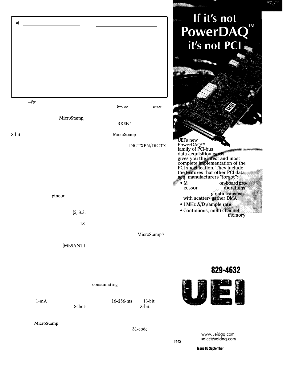
Shift Code/Shifted
Code A-D
b)
Shift Code l/Shifted Code 2 A-D
0
1110100
7
0
1110100
3
1110100
1110010
1
1110100
-1
1
1110100
-1
0111010
0111001
2
1110100
-1
2
1110100
3
0011101
1011100
3
1110100
-1
3
1110100
-1
1001110
0101110
4
1110100
-1
4
1110100
-1
0100111
0010111
5
1110100
1
5
1110100
-5
1010011
1001011
6
1110100
-1
6
1110100
3
1101001
1100101
7
1110100
7
7
1110100
3
1110100
1110010
Table 1
reliable code detection, codes should be chosen for low self- and cross-correlation. a-A code se-
quence exhibits good (low) se/f-correlation with phase-shifted replicas of itself.
codes exhibit high
correlation, making discrimination more ambiguous.
Figure 2 diagrams the
which includes a complete 2.44175GHz
spread-spectrum radio coupled with an
micro. A portion of the latter’s
RAM (256 bytes) is intended for appli-
cation data storage. Ten bytes are des-
ignated ID info, using a format that
assigns a portion for industry, specialty,
and user codes (four, two, and four
bytes, respectively).
Together, the radio, micro, and
RAM compose a complete RF-ID solu-
tion, but the real potential lies in the
digital hooks that are also provided.
Let’s run through the
in Figure 3,
and you’ll see what I mean.
Dispensing with the seven of the
chip’s 20 pins devoted to power
and 2.6-3.6-V versions are available),
ground, and no connect leaves only
to deal with. Of these, three are needed
for RF-only applications.
One (RXANT) serves as the receiver
antenna, while two others
and MBSANT2; the MBS stands for
Modulated Backscatter) connect to the
transmitter antenna.
For short range (10-15’) benign
applications, a few inches of PC trace
work fine (see Figure 4). However, both
the transmitter and receiver support
external boosters with pins MBSANT3
and RXIN, respectively. MBSANT3
modulates a
current into a PIN
diode, while RXIN connects to a
tky diode for increased sensitivity.
When the external receiver option
is used, the
asserts the
WAKEUP* output periodically to turn
on the external receiver and listen for
interrogation. Complementing that
function, the
input offers some-
thing like earmuffs. When deasserted,
it prevents
from waking up.
The six remaining pins make the
digital connection.
DATA and DIGRXEN/DIGRXDATA
enable transmission or reception (or
both) to be routed through pins rather
than airwaves. Besides use in one-way
applications, these prove a boon to
hardware and software debug.
However, employing the DIG pins
for application use does demand rather
profound software to deal with the
details of the communication protocol.
(More in a moment.)
If you just want to send a byte or
two, take advantage of the DPCLK and
DPDATA pins, which implement a
bidirectional clock serial (i.e., shift
register type) interface.
command set includes commands to
read/write the DP port (l-64 bytes per
command), along with those to read/
write the ID and RAM.
RADIO ROUND TRIP
Let’s follow a complete interrogation
and response to see what’s involved in
a wireless connection.
The interrogator issues a command
or query with a packet composed of
preamble
O
S
), a
barker
(i.e., start or sync) code,
data (8
data and 5 ECC bits), followed by a
16-bit packet checksum.
Each bit in the packet is transmitted
as one full cycle of a
(i.e., five
stage) PN sequence:
otorola 66 MHz
supervises%
l
Bus-masterin
streaming to system
l
Simultaneous analog and digi-
tal input and output
l
Clean 32-bit drivers for
Windows 95 &Windows NT
l
DLL library supplied with each
board (includes source code)
Call
today
for your free catalog:
(800)
United Electronic Industries
10
Dexter Ave, Watertown, MA 02172
Tel: (617) 924-l 155
Fax: (617) 924-1441
internet:
E-mail:
Circuit Cellar
INK@
1997
83
Figure
an RF-only (i.e., no
application, on/y
a
are
needed. For
applications,
antennas are
adequate.
001101001000010 1011 101100011111
The interrogator simply on/off mod-
ulates the
carrier using the
PN sequence for 1 or the inverted PN
sequence for 0. The modulation clock
(often referred to as the code or “chip”
rate] is 9.5375 MHz.
Thus, the baseband (i.e., your) data
rate, considering data ECC (but not
other packet overhead like the pre-
amble and checksum) is about
190 kbps:
8
31
That’s plenty fast for most applica-
tions and certainly much faster than
low-frequency (i.e., garage-door-opener
class) units.
Figure 5 happens to show the
power-consumption profile of the
but it serves equally well
to walk through operations at the
receiving end.
Sometimes I wish I was a chip-at
least one like this that spends most of
its time sleeping, consuming a few
microamps. Periodically (program-
mable as 16, 64, or 256 ms), the Micro-
Stamp wakes itself up (750
and
turns the receiver on
1.8
to listen
gator. If the preamble is detected, the
chip goes to full power (5
to re-
ceive the message.
After a short delay
= 3 ms
max., 3.8
the chip switches to
return link mode (4.2
The
scatter technique relies on the interro-
gator sending a raw (2.44175
carrier.
The
biphase modulates
the response onto a
carrier that opens and closes the trans-
mit antenna switch
and
MBSANT2).
Connected to a simple dipole (i.e.,
equal wires connected to each pin),
this setup effectively switches be-
tween the electrical equivalent of a
single half-wavelength antenna that
reflects much of the interrogator’s
transmission or two quarter-wave-
length antennas which don’t.
A couple other features just about
wrap it up. First, you may be wonder-
ing how multiple units in proximity
manage with just a single PN code.
Finally, the
includes a
low-battery detector that returns the
status with each query. The interroga-
tor can issue an alert when it detects a
tag whose battery is running low.
As it happens, arbitration is handled
at higher layers of the protocol. To
that end, a pseudorandom number
generator (more shift registers) is in-
cluded to assign node
schedule
retries, and otherwise resolve or avoid
collisions.
TUNE IN
Micron offers a complete line of
tools and training, though most of it is
rather pricey. For example, an
level simulator that enables exercising
a
connected via cable to a
for a query [preamble) from the interro-
PC runs $975.
Wakeup
Processor On
RX
On
All Oft
lddl
Preamble
Preamble
sage
sage
Mode
Receive Mode
Mode
Mode
Figure
5-The
wakes
up
periodically to check
for queries from an interroga-
tor. It responds by reflecting a
modulation of the interrogators
carrier back if.
A full-blown development system
costs $5525, while the all-important
interrogator is $5200. The
themselves start at under $50 in singles,
dropping to $10 in high volume (i.e.,
10 million).
If there are any clouds on the hori-
zon, they revolve around standards-or
more accurately, contention for control
between a number of vested interests.
Micron points out that the Micro-
Stamp, thanks to on-chip MCU, can
programmably adapt as the standards
situation evolves.
Specifically, they mention work in
progress under the auspices of ANSI
Notably, that proposal also
relies on 2.45
a frequency that
seems to be emerging as a worldwide
favorite.
Connecting radios and computers
isn’t a new idea. Search old hacker
archives, and
you’re
likely to find pro-
grams for Altairs or PDP-1 that can
play a little ditty on a nearby radio.
Clearly, technology like the Micro-
Stamp is going to enable much more
meaningful communication, without
all the wires that bind.
Tom Cantrell has been working on
chip, board, and systems design and
marketing in Silicon Valley for more
than ten years. You may reach him by
E-mail at
corn, by telephone at (510) 657-0264,
or by fax at (510)
R.C. Dixon, Spread Spectrum
Systems with Commercial Appli-
cations, Wiley Sons, New York,
NY, 1994.
Micron Communications, Inc.
3 176 S. Denver Way
Boise, ID 83707-0006
(208) 333-7481
Fax: (208) 333-7307
www.microncommunications.com
422 Very Useful
423 Moderately Useful
424 Not Useful
84
Issue 86 September 1997
Circuit Cellar INK@

INTERRUPT
I’m the Reader
nless you have a particular axe to grind, an endangered species to save, or piles of money to burn,
becoming a publisher wouldn’t be among an engineers normal career objectives on the way up the corporate
ladder. Trading a career at the edge of electronic discovery for a job that’s a figure-juggling balance of editorial
expenditure, advertising receipts, and printing-press physics can leave a lot to be desired. Fortunately, I’m the Editorial
Director/Publisher, so I get to delegate a bunch of that stuff and select from the rest.
Anyone looking at
the first time these days hopefully comes away with the impression that it’s a combination of superbly crafted
editorial, careful targeting, and the results of painstakingly studied analyses. I say this rather tongue-in-cheek. In actuality,
started
because I really did have an axe to grind, an endangered species to save (us!), and I didn’t care about the money.
Of course, while a cause drives the spirit, only hard cash runs the press. Fortunately, I’ve had good people and good advice over the
years, and we’ve prospered together. The business of publishing is still nothing more than a numbers game, but I can tolerate the periodic
discomfort of making financial decisions because the other half of the job still feels like we’re supporting a cause and a direction that
shouldn’t be abandoned. The focus title of
first issue was “inside the Box Still Counts.” It was my way of saying that for all the
shelf computer solutions available, somewhere back in the lab, there had to be an engineer who fabricated that solution. It’s not enough that
everyone learns how to build brick houses. Somewhere, there has to be somebody who knows how to make bricks.
By coincidence or subconscious design can’t really say which), whatever I’ve been interested in technically has also interested a
great deal of other solution-oriented engineers. Ken shares the same intuition. Selecting the projects and articles we publish is simply a
matter of deciding whether we like them ourselves, We both know that there will be lots more people interested in building houses, but we
still enjoy making the bricks.
The major consequence of using yourself as the sole data point in an analytical conclusion is that if you count it wrong, it’s 100%
wrong! These days, age has tempered my eagerness to join causes, but it hasn’t resulted in dementia yet. The shear momentum of an
established magazine and the fiscal responsibilities it implies does occasionally invite challenge to an editorial direction based solely on
intuition, however.
To reaffirm the validity and consequence of gut feelings, last month, we sent a detailed questionnaire to a randomly selected group of
While the results are still being tabulated, I’m happy to say that it still appears the vast majority of
readers have
interests similar to yours truly. Most of you like
the way it is. You still want hardware projects, devour anything and everything on
analog or digital interfacing, and think sensors, signal processing, and robotics are worthy topics, The prevailing conclusion of the survey is
that your primary interest is application, application, and application. I guess everyone agrees with our subtitle.
Most frequently, you are a technical specialist or engineer working primarily on product design or manufacturing. Like me, you have a
pile of trade magazines on the corner of your desk, and after you’ve completely read
you
keep it for reference. If you have time to read
the trades, after
you most frequently read
Times, and Electronic Design. 95% of us still purchase things by mail order, but
these days, we’re more than twice as likely to go check out a company’s Web site rather than call directly for more information. Best of all,
virtually everyone thinks the price of an
is just right!
I feel confident that our cause and spirit is reiterated. Surveys are expensive and not something you do on a whim. Most gratifying is
that it tells us that we don’t have to make any major course corrections and that gut instinct can be right.
Of course, instinct is hard to sell to ad reps and advertisers. They like to see scientific surveys. OK, no problem. Got questions about
our audience demographics? Send ‘em to me. Apparently, I’m well-qualified to fill out the survey.
6
Issue 86 September 1997
Circuit Cellar INK@
Wyszukiwarka
Podobne podstrony:
circuit cellar1996 09
circuit cellar2004 09
circuit cellar1995 09
circuit cellar2000 09
circuit cellar1993 09
circuit cellar2001 09
circuit cellar2002 09
circuit cellar2003 09
circuit cellar1994 09
circuit cellar1996 09
circuit cellar2003 09
circuit cellar1994 09
circuit cellar1997 09
circuit cellar1993 09
circuit cellar2004 09
circuit cellar1995 09
circuit cellar1996 09
więcej podobnych podstron