1
BST L5
Lab A, Securing Layer 2 Switches
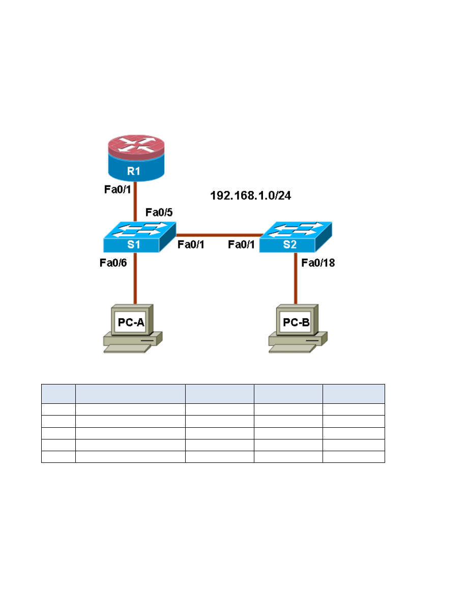
Topology
IP Addressing Table
Device
Interface
IP Address
Subnet Mask
Default Gateway
Switch Port
R1
Fa0/1
192.168.1.1
255.255.255.0
N/A
S1 FA0/5
S1
VLAN 1
192.168.1.2
255.255.255.0
N/A
N/A
S2
VLAN 1
192.168.1.3
255.255.255.0
N/A
N/A
PC-A
NIC
192.168.1.10
255.255.255.0
192.168.1.1
S1 FA0/6
PC-B
NIC
192.168.1.11
255.255.255.0
192.168.1.1
S2 FA0/18
Objectives
Part 1: Configure Basic Switch Settings
• Build the topology.
• Configure the host name, IP address, and access passwords.
Part 2: Configure SSH Access to the Switches

2
• Configure SSH access on the switch.
• Configure an SSH client to access the switch.
• Verify the configuration.
Part 3: Secure Trunks and Access Ports
• Configure trunk port mode.
• Change the native VLAN for trunk ports.
• Verify trunk configuration.
• Enable storm control for broadcasts.
• Configure access ports.
• Enable PortFast and BPDU guard.
• Verify BPDU guard.
• Enable root guard.
• Configure port security.
• Verify port security.
• Disable unused ports.
Part 4: Configure SPAN and Monitor Traffic
• Configure Switched Port Analyzer (SPAN).
• Monitor port activity using Wireshark.
• Analyze a sourced attack.
Background
The Layer 2 (Data Link) infrastructure consists mainly of interconnected Ethernet switches. Most end-user
devices, such as computers, printers, IP phones and other hosts, connect to the network via Layer 2 access
switches. As a result, they can present a network security risk. Similar to routers, switches are subject to
attack from malicious internal users. The switch Cisco IOS software provides many security features that are
specific to switch functions and protocols.
In this lab, you configure SSH access and Layer 2 security for switches S1 and S2. You also configure
various switch protection measures, including access port security, switch storm control, and Spanning Tree
Protocol (STP) features such as BPDU guard and root guard. Lastly, you use Cisco SPAN to monitor traffic to
specific ports on the switch.
Note: The router commands and output in this lab are from a Cisco 1841 with Cisco IOS Release 12.4(20)T
(Advanced IP image). The switch commands and output are from a Cisco WS-C2960-24TT-L with Cisco IOS
Release 12.2(46)SE (C2960-LANBASEK9-M image). Other routers, switches, and IOS versions may be used.
See the Router Interface Summary table at the end of the lab to determine which interface identifiers to use
based on the equipment in the lab. Depending on the router or switch model and IOS version, the commands
available and output produced might vary from what is shown in this lab.
Note: Make sure that the router and the switches have been erased and have no startup configurations.

3
Required Resources
• One router (Cisco 1841 with Cisco IOS Release 12.4(20)T1 or comparable)
• Two switches (Cisco 2960 or comparable with cryptography IOS image for SSH support – Release
12.2(46)SE or comparable)
• PC-A (Windows XP or Vista with a PuTTY SSH client and Wireshark)
• PC-B (Windows XP or Vista with a PuTTY SSH client and SuperScan)
• Ethernet cables as shown in the topology
• Rollover cables to configure the switches via the console
Part 1: Basic Device Configuration
In Part 1 of this lab, you set up the network topology and configure basic settings such as the host names, IP
addresses, and device access passwords.
Note: Perform all tasks on router R1 and switches S1 and S2. The procedure for S1 is shown here as an
example.
Step 1: Cable the network as shown in the topology.
Attach the devices shown in the topology diagram and cable as necessary.
Step 2: Configure basic settings for the router and each switch.
a. Configure host names as shown in the topology.
b. Configure interface IP addresses as shown in the IP Addressing Table. The configuration of the
VLAN 1 management interface on switch S1 is shown here.
S1(config)#interface vlan 1
S1(config-if)#ip address 192.168.1.2 255.255.255.0
S1(config-if)#no shutdown
c. Configure the enable secret and console passwords.
S1(config)#enable secret cisco12345
S1(config)#line console 0
S1(config-line)#password ciscoconpass
S1(config-line)#exec-timeout 5 0
S1(config-line)#login
S1(config-line)#logging synchronous
Note: Do not configure the switch vty access at this time. The vty lines are configured on the switches
in Part 2 for SSH access.
d. Configure the vty lines and password on R1.
R1(config)#line vty 0 4
R1(config-line)#password ciscovtypass
R1(config-line)#exec-timeout 5 0

4
R1(config-line)#login
e. To prevent the router or switch from attempting to translate incorrectly entered commands, disable
DNS lookup. Router R1 is shown here as an example.
R1(config)#no ip domain-lookup
f.
HTTP access to the switch is enabled by default. To prevent HTTP access, disable the HTTP server
and HTTP secure server.
S1(config)#no ip http server
S1(config)#no ip http secure-server
Note: The switch must have a cryptography IOS image to support the ip http secure-server
command. HTTP access to the router is disabled by default.
Step 3: Configure PC host IP settings.
Configure a static IP address, subnet mask, and default gateway for PC-A and PC-B as shown in the IP
Addressing Table.
Step 4: Verify basic network connectivity.
a. Ping from PC-A and PC-B to the R1 Fa0/1 interface at IP address 192.168.1.1. Were the results
successful? _____
If the pings are not successful, troubleshoot the basic device configurations before continuing.
b. Ping from PC-A to PC-B. Were the results successful? _____
If the pings are not successful, troubleshoot the basic device configurations before continuing.
Step 5: Save the basic configurations for the router and both switches.
Save the running configuration to the startup configuration from the privileged EXEC prompt.
S1#copy running-config startup-config

5
Part 2: SSH Configuration
In Part 2 of this lab, you configure switches S1 and S2 to support SSH connections and install SSH client
software on the PCs.
Note: A switch IOS image that supports encryption is required to configure SSH. Otherwise, you cannot
specify SSH as an input protocol for the vty lines and the crypto commands are not available.
Task 1: Configure the SSH Server on Switch S1 and S2 Using the CLI
In this task, use the CLI to configure the switch to be managed securely using SSH instead of Telnet. Secure
Shell (SSH) is a network protocol that establishes a secure terminal emulation connection to a switch or other
networking device. SSH encrypts all information that passes over the network link and provides authentication
of the remote computer. SSH is rapidly replacing Telnet as the remote login tool of choice for network
professionals.
Note: For a switch to support SSH, it must be configured with local authentication, AAA services or
username. In this task, you configure an SSH username and local authentication on S1 and S2. S1 is shown
here as an example.
Step 1: Configure a domain name.
Enter global configuration mode and set the domain name.
S1#conf t
S1(config)#ip domain-name ccnasecurity.com
Step 2: Configure a privileged user for login from the SSH client.
a. Use the username command to create the user ID with the highest possible privilege level and a
secret password.
S1(config)#username admin privilege 15 secret cisco12345
b. Exit to the initial switch login screen, and log in with this username. What was the switch prompt after
you entered the password? __________________________________________________________
Step 3: Configure the incoming vty lines.
a. Configure vty access on lines 0 through 4. Specify a privilege level of 15 so that a user with the
highest privilege level (15) will default to privileged EXEC mode when accessing the vty lines. Other
users will default to user EXEC mode. Specify the use of local user accounts for mandatory login and
validation, and accept only SSH connections.
S1(config)#line vty 0 4
S1(config-line)#privilege level 15
S1(config-line)#exec-timeout 5 0
S1(config-line)#login local
S1(config-line)#transport input ssh
S1(config-line)#exit
b. Disable login for switch vty lines 5 through 15.
S1(config)#line vty 5 15
S1(config-line)#no login

6
Step 4: Generate the RSA encryption key pair for the router.
The switch uses the RSA key pair for authentication and encryption of transmitted SSH data.
Configure the RSA keys with 1024 for the number of modulus bits. The default is 512, and the range is
from 360 to 2048.
S1(config)#crypto key generate rsa general-keys modulus 1024
The name for the keys will be: S1.ccnasecurity.com
% The key modulus size is 1024 bits
% Generating 1024 bit RSA keys, keys will be non-exportable...[OK]
S1(config)#
00:15:36: %SSH-5-ENABLED: SSH 1.99 has been enabled
Note: The details of encryption methods are covered in Chapter 7.
Step 5: Verify the SSH configuration.
a. Use the show ip ssh command to see the current settings.
S1#show ip ssh
b. Fill in the following information based on the output of the show ip ssh command.
SSH version enabled: __________________
Authentication timeout: __________________
Authentication retries: __________________
Step 6: Configure SSH timeouts and authentication parameters.
The default SSH timeouts and authentication parameters can be altered to be more restrictive using the
following commands.
S1(config)#ip ssh time-out 90
S1(config)#ip ssh authentication-retries 2
Step 7: Save the running-config to the startup-config.
S1#copy running-config startup-config
Task 2: Configure the SSH Client
TeraTerm and PuTTY are two terminal emulation programs that can support SSHv2 client connections. This
lab uses PuTTY.
Step 1: (Optional) Download and install an SSH client on PC-A and PC-B.
If the SSH client is not already installed, download either TeraTerm or PuTTY.
Note: The procedure described here is for PuTTY and pertains to PC-A.
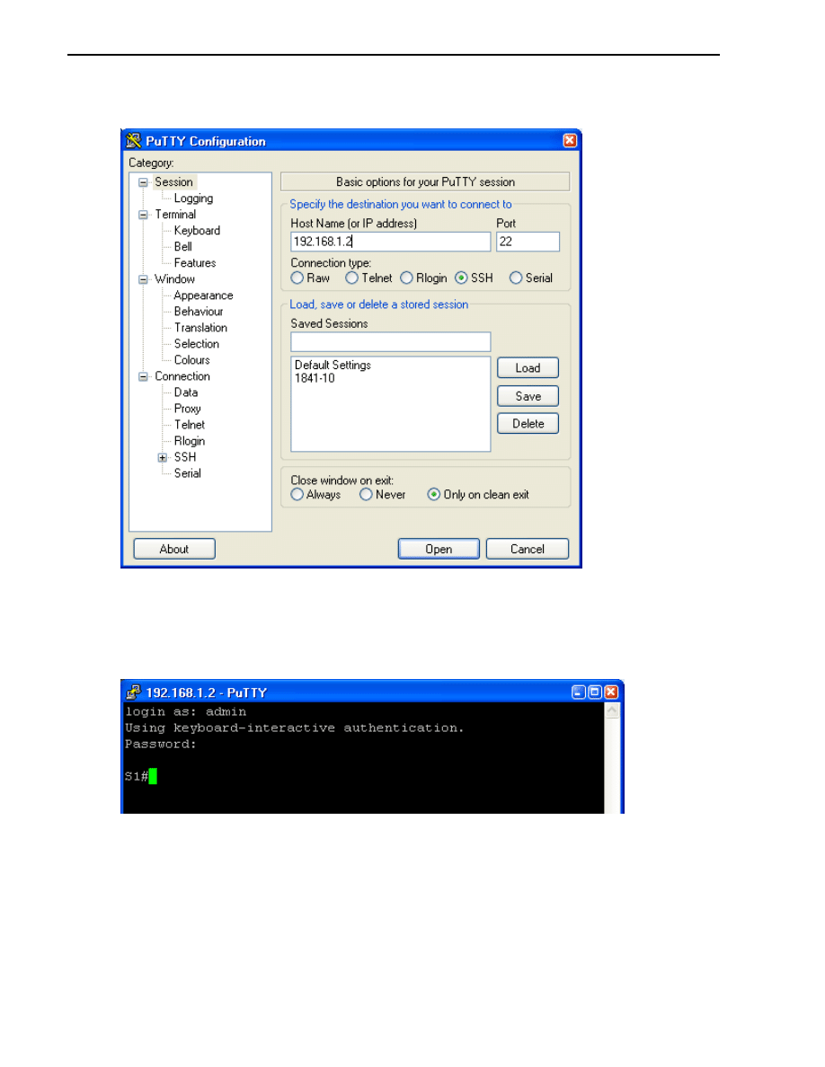
Step 2: Verify SSH connectivity to S1 from PC-A.
a. Launch PuTTY by double-clicking the putty.exe icon.
b. Input the S1 IP address 192.168.1.2 in the Host Name or IP address field.
7
c. Verify that the SSH radio button is selected. PuTTY defaults to SSH version 2.
d. Click Open.
e. In the PuTTY Security Alert window, click Yes.
f.
Enter the admin username and password cisco12345 in the PuTTY window.
g. At the S1 privileged EXEC prompt, enter the show users command.
S1#show users
What users are connected to switch S1 at this time?
______________________________________________________________________________
h. Close the PuTTy SSH session window with the exit or quit command.

8
i.
Try to open a Telnet session to switch S1 from PC-A. Were you able to open the Telnet session?
Why or why not? _______________________________________________________________
Step 3: Save the configuration.
Save the running configuration to the startup configuration from the privileged EXEC prompt.
R1#copy running-config startup-config
Part 3: Secure Trunks and Access Ports
In Part 3 of this lab, you configure trunk ports, change the native VLAN for trunk ports, verify trunk
configuration, and enable storm control for broadcasts on the trunk ports.
Securing trunk ports can help stop VLAN hopping attacks. The best way to prevent a basic VLAN hopping
attack is to turn off trunking on all ports except the ones that specifically require trunking. On the required
trunking ports, disable DTP (auto trunking) negotiations and manually enable trunking. If no trunking is
required on an interface, configure the port as an access port. This disables trunking on the interface.
Note: Tasks should be performed on switches S1 or S2 as indicated.
Task 1: Secure Trunk Ports
Step 1: Configure switch S1 as the root switch.
For the purposes of this lab, assume that switch S2 is currently the root bridge and that switch S1 is preferred
as the root switch. To force S1 to become the new root bridge, you configure a new priority for it.
a. From the console on S1, enter privileged EXEC mode and then global configuration mode.
b. The default priority for switches S1 and S2 is 32769 (32768 + 1 with System ID Extension). Set S1
priority to 0 so that it becomes the root switch.
S1(config)#spanning-tree vlan 1 priority 0
S1(config)#exit
c. Issue the show spanning-tree command to verify that S1 is the root bridge and to see the ports in
use and their status.
S1#show spanning-tree
VLAN0001
Spanning tree enabled protocol ieee
Root ID Priority 1
Address 001d.4635.0c80
This bridge is the root
Hello Time 2 sec Max Age 20 sec Forward Delay 15 sec
Bridge ID Priority 1 (priority 0 sys-id-ext 1)
Address 001d.4635.0c80
Hello Time 2 sec Max Age 20 sec Forward Delay 15 sec
Aging Time 300
Interface Role Sts Cost Prio.Nbr Type

9
---------------- ---- --- --------- -------- --------------------------
------
Fa0/1 Desg FWD 19 128.1 P2p
Fa0/5 Desg FWD 19 128.5 P2p
Fa0/6 Desg FWD 19 128.6 P2p
d. What is the S1 priority? ______________________________________________________
e. What ports are in use and what is their status? ____________________________________
Step 2: Configure trunk ports on S1 and S2.
a. Configure port Fa0/1 on S1 as a trunk port.
S1(config)#interface FastEthernet 0/1
S1(config-if)#switchport mode trunk
b. Configure port Fa0/1 on S2 as a trunk port.
S2(config)#interface FastEthernet 0/1
S2(config-if)#switchport mode trunk
c. Verify that S1 port Fa0/1 is in trunking mode with the show interfaces trunk command.
S1#show interfaces trunk
Port Mode Encapsulation Status Native vlan
Fa0/1 on 802.1q trunking 1
Port Vlans allowed on trunk
Fa0/1 1-4094
Port Vlans allowed and active in management domain
Fa0/1 1
Port Vlans in spanning tree forwarding state and not pruned
Fa0/1 1
Step 3: Change the native VLAN for the trunk ports on S1 and S2.
Changing the native VLAN for trunk ports to an unused VLAN helps prevent VLAN hopping attacks.
a. From the output of the show interfaces trunk in the previous step, what is the current native
VLAN for the S1 Fa0/1 trunk interface? ______________________________________________
b. Set the native VLAN on the S1 Fa0/1 trunk interface to an unused VLAN 99.
S1(config)#interface Fa0/1
S1(config-if)#switchport trunk native vlan 99
S1(config-if)#end
c. The following message should be displayed after a brief period of time.
02:16:28: %CDP-4-NATIVE_VLAN_MISMATCH: Native VLAN mismatch discovered
on FastEthernet0/1 (99), with S2 FastEthernet0/1 (1).
What does the message mean? __________________________________________________
d. Set the native VLAN on the S2 Fa0/1 trunk interface to VLAN 99.

10
S2(config)#interface Fa0/1
S2(config-if)#switchport trunk native vlan 99
S2(config-if)#end
Step 4: Prevent the use of DTP on S1 and S2.
Setting the trunk port to not negotiate also helps to mitigate VLAN hopping by turning off the generation of
DTP frames.
S1(config)#interface Fa0/1
S1(config-if)#switchport nonegotiate
S2(config)#interface Fa0/1
S2(config-if)#switchport nonegotiate
Step 5: Verify the trunking configuration on port Fa0/1.
S1#show interface fa0/1 trunk
Port Mode Encapsulation Status Native vlan
Fa0/1 on 802.1q trunking 99
Port Vlans allowed on trunk
Fa0/1 1-4094
Port Vlans allowed and active in management domain
Fa0/1 1
Port Vlans in spanning tree forwarding state and not pruned
Fa0/1 1
S1#show interface fa0/1 switchport
Name: Fa0/1
Switchport: Enabled
Administrative Mode: trunk
Operational Mode: trunk
Administrative Trunking Encapsulation: dot1q
Operational Trunking Encapsulation: dot1q
Negotiation of Trunking: Off
Access Mode VLAN: 1 (default)
Trunking Native Mode VLAN: 99 (Inactive)
Administrative Native VLAN tagging: enabled
Voice VLAN: none
Administrative private-vlan host-association: none
Administrative private-vlan mapping: none
Administrative private-vlan trunk native VLAN: none
Administrative private-vlan trunk Native VLAN tagging: enabled
Administrative private-vlan trunk encapsulation: dot1q
Administrative private-vlan trunk normal VLANs: none
Administrative private-vlan trunk private VLANs: none
Operational private-vlan: none
Trunking VLANs Enabled: ALL
Pruning VLANs Enabled: 2-1001
Capture Mode Disabled
Capture VLANs Allowed: ALL
Protected: false

11
Unknown unicast blocked: disabled
Unknown multicast blocked: disabled
Appliance trust: none
Step 6: Enable storm control for broadcasts.
Enable storm control for broadcasts on the trunk port with a 50 percent rising suppression level using the
storm-control broadcast
command.
S1(config)#interface FastEthernet 0/1
S1(config-if)#storm-control broadcast level 50
S2(config)#interface FastEthernet 0/1
S2(config-if)#storm-control broadcast level 50
Step 7: Verify your configuration with the show run command.
Use the show run command to display the running configuration, beginning with the first line that has
the text string “0/1” in it.
S1#show run | beg 0/1
interface FastEthernet0/1
switchport trunk native vlan 99
switchport mode trunk
switchport nonegotiate
storm-control broadcast level 50.00
<Output omitted>
Task 2: Secure Access Ports
By manipulating the STP root bridge parameters, network attackers hope to spoof their system, or a rogue
switch that they add to the network, as the root bridge in the topology. If a port that is configured with PortFast
receives a BPDU, STP can put the port into the blocking state by using a feature called BPDU guard.
Step 1: Disable trunking on S1 access ports.
a. On S1, configure Fa0/5, the port to which R1 is connected, as access mode only.
S1(config)#interface FastEthernet 0/5
S1(config-if)#switchport mode access
b. On S1, configure Fa0/6, the port to which PC-A is connected, as access mode only.
S1(config)#interface FastEthernet 0/6
S1(config-if)#switchport mode access
c. On S2, configure Fa0/18, the port to which PC-B is connected, as access mode only.
S2(config)#interface FastEthernet 0/18
S2(config-if)#switchport mode access
Task 3: Protect Against STP Attacks
The topology has only two switches and no redundant paths, but STP is still active. In this step, you enable
some switch security features that can help reduce the possibility of an attacker manipulating switches via
STP-related methods.

12
Step 1: Enable PortFast on S1 and S2 access ports.
PortFast is configured on access ports that connect to a single workstation or server to enable them to
become active more quickly.
a. Enable PortFast on the S1 Fa0/5 access port.
S1(config)#interface FastEthernet 0/5
S1(config-if)#spanning-tree portfast
The following Cisco IOS warning message is displayed:
%Warning: portfast should only be enabled on ports connected to a
single host. Connecting hubs, concentrators, switches, bridges, etc...
to this interface when portfast is enabled, can cause temporary
bridging loops. Use with CAUTION
%Portfast has been configured on FastEthernet0/5 but will only
have effect when the interface is in a non-trunking mode.
b. Enable PortFast on the S1 Fa0/6 access port.
S1(config)#interface FastEthernet 0/6
S1(config-if)#spanning-tree portfast
c. Enable PortFast on the S2 Fa0/18 access ports
S2(config)#interface FastEthernet 0/18
S2(config-if)#spanning-tree portfast
Step 2: Enable BPDU guard on the S1 and S2 access ports.
BPDU guard is a feature that can help prevent rogue switches and spoofing on access ports.
a. Enable BPDU guard on the switch ports previously configured as access only.
S1(config)#interface FastEthernet 0/5
S1(config-if)#spanning-tree bpduguard enable
S1(config)#interface FastEthernet 0/6
S1(config-if)#spanning-tree bpduguard enable
S2(config)#interface FastEthernet 0/18
S2(config-if)#spanning-tree bpduguard enable
b. PortFast and BPDU guard can also be enabled globally with the spanning-tree portfast
default
and spanning-tree portfast bpduguard commands in global configuration mode.
Note: BPDU guard can be enabled on all access ports that have PortFast enabled. These ports
should never receive a BPDU. BPDU guard is best deployed on user-facing ports to prevent rogue
switch network extensions by an attacker. If a port enabled with BPDU guard receives a BPDU, it is
disabled and must be manually re-enabled. An err-disable timeout can be configured on the port so
that it can recover automatically after a specified time period.
c. Verify that BPDU guard is configured by using the show spanning-tree interface fa0/5
detail
command on switch S1.
S1#show spanning-tree interface fa0/5 detail
Port 5 (FastEthernet0/5) of VLAN0001 is designated forwarding

13
Port path cost 19, Port priority 128, Port Identifier 128.5.
Designated root has priority 1, address 001d.4635.0c80
Designated bridge has priority 1, address 001d.4635.0c80
Designated port id is 128.5, designated path cost 0
Timers: message age 0, forward delay 0, hold 0
Number of transitions to forwarding state: 1
The port is in the portfast mode
Link type is point-to-point by default
Bpdu guard is enabled
BPDU: sent 3349, received 0
Step 3: (Optional) Enable root guard.
Root guard is another option in helping to prevent rogue switches and spoofing. Root guard can be enabled
on all ports on a switch that are not root ports. It is normally enabled only on ports connecting to edge
switches where a superior BPDU should never be received. Each switch should have only one root port,
which is the best path to the root switch.
a. The following command configures root guard on S2 interface Gi0/1. Normally, this is done if another
switch is attached to this port. Root guard is best deployed on ports that connect to switches that
should not be the root bridge.
S2(config)#interface gigabitEthernet 0/1
S2(config-if)#spanning-tree guard root
b. Issue the show run command to verify that root guard is configured.
S2#sh run | beg Gig
interface GigabitEthernet0/1
spanning-tree guard root
Note: The S2 Gi0/1 port is not currently up, so it is not participating in STP. Otherwise, you could use
the show spanning-tree interface Gi0/1 detail command.
c. If a port that is enabled with BPDU guard receives a superior BPDU, it goes into a root-inconsistent
state. Use the show spanning-tree inconsistentports command to determine if there are
any ports currently receiving superior BPDUs that should not be.
S2#show spanning-tree inconsistentports
Name Interface Inconsistency
-------------------- ---------------------- ------------------
Number of inconsistent ports (segments) in the system : 0
Note: Root guard allows a connected switch to participate in STP as long as the device does not try to
become the root. If root guard blocks the port, subsequent recovery is automatic. If the superior BPDUs
stop, the port returns to the forwarding state.
Task 4: Configure Port Security and Disable Unused Ports
Switches can also be subject to CAM table overflow, MAC spoofing attacks, and unauthorized connections to
switch ports. In this task, you configure port security to limit the number of MAC addresses that can be
learned on a switch port and disable the port if that number is exceeded.
Step 1: Record the R1 Fa0/0 MAC address.
a. From the router R1 CLI, use the show interface command and record the MAC address of the
interface.

14
R1#show interface fa0/1
FastEthernet0/1 is up, line protocol is up
Hardware is Gt96k FE, address is 001b.5325.256f (bia 001b.5325.256f)
Internet address is 192.168.1.1/24
MTU 1500 bytes, BW 100000 Kbit/sec, DLY 100 usec,
reliability 255/255, txload 1/255, rxload 1/255
Encapsulation ARPA, loopback not set
Keepalive set (10 sec)
Full-duplex, 100Mb/s, 100BaseTX/FX
b. What is the MAC address of the R1 Fa0/1 interface? _____________________________________
Step 2: Configure basic port security.
This procedure should be performed on all access ports that are in use. Switch S1 port Fa0/5 is shown here
as an example.
Note: A switch port must be configured as an access port to enable port security.
a. From the switch S1 CLI, enter interface configuration mode for the port that connects to the router
(Fast Ethernet 0/5).
S1(config)#interface FastEthernet 0/5
b. Shut down the switch port.
S1(config-if)#shutdown
c. Enable port security on the port.
S1(config-if)#switchport port-security
Note: Entering just the switchport port-security command sets the maximum MAC
addresses to 1 and the violation action to shutdown. The switchport port-security maximum
and switchport port-security violation commands can be used to change the default
behavior.
d. Configure a static entry for the MAC address of R1 Fa0/1/ interface recorded in Step 1.
S1(config-if)#switchport port-security mac-address xxxx.xxxx.xxxx
(xxxx.xxxx.xxxx is the actual MAC address of the router Fast Ethernet 0/1 interface.)
Note: Optionally, you can use the switchport port-security mac-address sticky
command to add all the secure MAC addresses that are dynamically learned on a port (up to the
maximum set) to the switch running configuration.
e. Bring up the switch port.
S1(config-if)#no shutdown
Step 3: Verify port security on S1 Fa0/5.
a. On S1, issue the show port-security command to verify that port security has been configured
on S1 Fa0/5.
S1#show port-security interface f0/5
Port Security : Enabled
Port Status : Secure-up
Violation Mode : Shutdown

15
Aging Time : 0 mins
Aging Type : Absolute
SecureStatic Address Aging : Disabled
Maximum MAC Addresses : 1
Total MAC Addresses : 1
Configured MAC Addresses : 1
Sticky MAC Addresses : 0
Last Source Address:Vlan : 001b.5325.256f:1
Security Violation Count : 0
b. What is the status of the Fa0/5 port? ___________________________________________________
What is the Last Source Address and VLAN? _______________________________________________
c. From the router R1 CLI, ping PC-A to verify connectivity. This also ensures that the R1 Fa0/1 MAC
address is learned by the switch.
R1#ping 192.168.1.10
d. You will now violate security by changing the MAC address on the router interface. Enter interface
configuration mode for the Fast Ethernet 0/1 interface and shut it down.
R1(config)#interface FastEthernet 0/1
R1(config-if)#shutdown
e. Configure a MAC address for the interface on the interface, using aaaa.bbbb.cccc as the address.
R1(config-if)#mac-address aaaa.bbbb.cccc
f.
Enable the Fast Ethernet 0/1 interface.
R1(config-if)#no shutdown
R1(config-if)#end
g. From the router R1 CLI, ping PC-A. Was the ping successful? Why or why not?
_______________________________________________________________________________
h. On switch S1 console, observe the messages when port Fa0/5 detects the violating MAC address.
*Jan 14 01:34:39.750: %PM-4-ERR_DISABLE: psecure-violation error
detected on Fa0/5, putting Fa0/5 in err-disable state
*Jan 14 01:34:39.750: %PORT_SECURITY-2-PSECURE_VIOLATION: Security
violation occurred, caused by MAC address aaaa.bbbb.cccc on port
FastEthernet0/5.
*Jan 14 01:34:40.756: %LINEPROTO-5-UPDOWN: Line protocol on Interface
FastEthernet0/5, changed state to down
*Mar 1 01:34:41.755: %LINK-3-UPDOWN: Interface FastEthernet0/5,
changed state to down
i.
On the switch, use the various show port-security commands to verify that port security has
been violated.
S1#show port-security
Secure Port MaxSecureAddr CurrentAddr SecurityViolation Security Action
(Count) (Count) (Count)
--------------------------------------------------------------------
Fa0/5 1 1 1 Shutdown
----------------------------------------------------------------------
S1#show port-security interface fastethernet0/5
Port Security : Enabled
Port Status : Secure-shutdown

16
Violation Mode : Shutdown
Aging Time : 0 mins
Aging Type : Absolute
SecureStatic Address Aging : Disabled
Maximum MAC Addresses : 1
Total MAC Addresses : 1
Configured MAC Addresses : 1
Sticky MAC Addresses : 0
Last Source Address:Vlan : aaaa.bbbb.cccc:1
Security Violation Count : 1
S1#show port-security address
Secure Mac Address Table
-----------------------------------------------------------------------
-
Vlan Mac Address Type Ports Remaining Age
(mins)
---- ----------- ---- ----- -------------
1 001b.5325.256f SecureConfigured Fa0/5 -
-----------------------------------------------------------------------
j.
On the router, shut down the Fast Ethernet 0/1 interface, remove the hard-coded MAC address from
the router, and re-enable the Fast Ethernet 0/1 interface.
R1(config)#interface FastEthernet 0/1
R1(config-if)#shutdown
R1(config-if)#no mac-address aaaa.bbbb.cccc
R1(config-if)#no shutdown
Note: This will restore the original FastEthernet interface MAC address.
k. From R1, try to ping the PC-A again at 192.168.1.10. Was the ping successful? Why or why not?
________________________________________________________________________________
Step 4: Clear the S1 Fa0/5 error disabled status.
a. From the S1 console, clear the error and re-enable the port using the following commands. This will
change the port status from Secure-shutdown to Secure-up.
S1(config)#interface FastEthernet 0/5
S1(config-if)#shutdown
S1(config-if)#no shutdown
Note: This assumes the device/interface with the violating MAC address has been removed and replaced
with the one originally configured.
b. From R1, ping PC-A again. You should be successful this time.
R1#ping 192.168.1.10
Step 5: Remove basic port security on S1 Fa0/5.
a. From the S1 console, remove port security on Fa0/5. This procedure can also be used to re-enable
the port but port security commands will need to be reconfigured.
S1(config)#interface FastEthernet 0/5
S1(config-if)#shutdown
S1(config-if)#no switchport port-security
S1(config-if)#no switchport port-security mac-address 001b.5325.256f

17
S1(config-if)#no shutdown
b. You can also use the following commands to reset the interface to its default settings.
S1(config)#interface FastEthernet 0/5
S1(config-if)#shutdown
S1(config-if)#exit
S1(config)#default interface fastethernet 0/5
S1(config)#interface FastEthernet 0/5
S1(config-if)#no shutdown
Note: This default interface command also requires you to reconfigure the port as an access port
in order to re-enable the security commands.
Step 6: (Optional) Configure port security for VoIP.
The following example shows a typical port security configuration for a voice port. Two MAC addresses
are allowed, and they are to be learned dynamically. One MAC address is for the IP phone, and the other
IP address is for the PC connected to the IP phone. Violations of this policy result in the port being shut
down. The aging timeout for the learned MAC addresses is set to two hours.
This example is shown for switch S2 port Fa0/18.
S2(config)#interface Fa0/18
S2(config-if)#switchport mode access
S2(config-if)#switchport port-security
S2(config-if)#switchport port-security maximum 2
S2(config-if)#switchport port-security violation shutdown
S2(config-if)#switchport port-security mac-address sticky
S2(config-if)#switchport port-security aging time 120
Step 7: Disable unused ports on S1 and S2.
As a further security measure, disable any ports not being used on the switch.
a. Ports Fa0/1, Fa0/5, and Fa0/6 are used on switch S1. The remaining Fast Ethernet ports and the two
Gigabit Ethernet ports will be shutdown.
S1(config)#interface range Fa0/2 - 4
S1(config-if-range)#shutdown
S1(config-if-range)#interface range Fa0/7 - 24
S1(config-if-range)#shutdown
S1(config-if-range)#interface range gigabitethernet0/1 - 2
S1(config-if-range)#shutdown
b. Ports Fa0/18 and Gi0/1 are used on switch S2. The remaining Fast Ethernet ports and the Gigabit
Ethernet ports will be shutdown.
S2(config)#interface range Fa0/2 - 17
S2(config-if-range)#shutdown
S2(config-if-range)#interface range Fa0/19 - 24
S2(config-if-range)#shutdown
S2(config-if-range)#exit
S2(config)#interface gigabitethernet0/2
S2(config-if)#shutdown

18
Step 8: (Optional) Move active ports to a VLAN other than the default VLAN 1
As a further security measure, you can move all active end user and router ports to a VLAN other than the
default VLAN 1 on both switches.
a. Configure a new VLAN for users on each switch using the following commands:
S1(config)#vlan 20
S1(config-vlan)#name Users
S2(config)#vlan 20
S2(config-vlan)#name Users
b. Add the current active access (non-trunk) ports to the new VLAN.
S1(config)#interface range fa0/5 - 6
S1(config-if)#switchport access vlan 20
S2(config)#interface fa0/18
S2(config-if)#switchport access vlan 20
Note: This will prevent communication between end user hosts and the management VLAN IP address of the
switch, which is currently VLAN 1. The switch can still be accessed and configured using the console
connection.
If you need to provide Telnet or SSH access to the switch, a specific port can be designated as the
management port and added to VLAN 1 with a specific management workstation attached. A more elaborate
solution is to create a new VLAN for switch management (or use the existing native trunk VLAN 99) and
configure a separate subnet for the management and user VLANs. Enable trunking with subinterfaces on R1
to route between the management and user VLAN subnets.
Part 4: Configure SPAN and Monitor Traffic
Note: There are two tasks in this part of the lab, Task 1: Option 1 is to be performed using hands-on
equipment. Task 2: Option 2 is modified to be compatible with the NETLAB+ system but can also be
performed using hands-on equipment.
Cisco IOS provides a feature that can be used to monitor network attacks called Switched Port Analyzer
(SPAN). Cisco IOS supports local SPAN and remote SPAN (RSPAN). With local SPAN, the source VLANs,
source switch ports, and the destination switch ports are on the same physical switch.
In this part of the lab, you configure a local SPAN to copy traffic from one port where a host is connected to
another port where a monitoring station is connected. The monitoring station will run the Wireshark packet
sniffer application to analyze traffic.
Note: SPAN allows you to select and copy traffic from one or more source switch ports or source VLANs onto
one or more destination ports.

19
Task 1: Option 1 - Configure a SPAN Session Using Hands-on Equipment.
Note: Option 1 assumes you have physical access to the devices shown in the topology for this
lab. NETLAB+ users accessing lab equipment remotely should proceed to Task 2: Option 2.
Step 1: Configure a SPAN session on S1 with a source and destination
a. Set the SPAN source interface using the monitor session command in global configuration mode.
The following configures a SPAN source port on FastEthernet 0/5 for ingress and egress traffic.
Traffic copied on the source port can be ingress only, egress only or both. Switch S1 port Fa0/5 is
connected to router R1, so traffic to (ingress) and from (egress) switch port Fa0/5 to R1 will be
monitored.
S1(config)#monitor session 1 source interface fa0/5 both
Note: You can specify to monitor tx (transmit) or rx (receive) traffic. The keyword both includes tx
and rx. The source can be a single interface, a range of interfaces, a single VLAN, or a range of
VLANs.
b. Set the SPAN destination interface.
S1(config)#monitor session 1 destination interface fa0/6
All traffic from S1 Fa0/5, where R1 is connected, will be copied to the SPAN destination port Fa0/6, where
PC-A with Wireshark is connected.
Note: The destination can be an interface or a range of interfaces.
Step 2: Verify the setup of the SPAN session on S1.
Confirm the SPAN session setup.
S1#show monitor session 1
Session 1
---------
Type : Local Session
Source Ports :
Both : Fa0/5
Destination Ports : Fa0/6
Encapsulation : Native
Ingress : Disabled
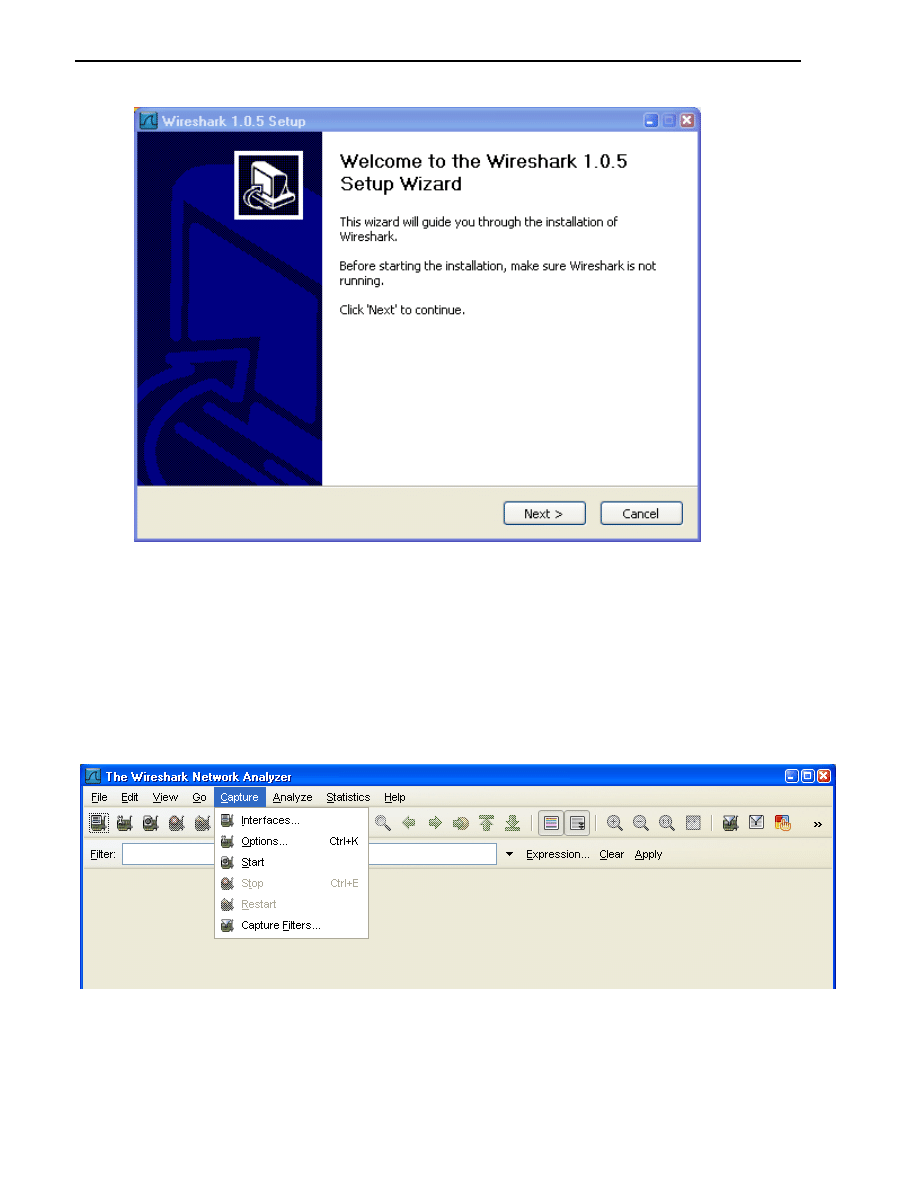
Step 3: (Optional) Download and install Wireshark on PC-A.
a. Wireshark is a network protocol analyzer (also called a packet sniffer) that runs with Windows XP and
Vista. If Wireshark is not currently available on PC-A, you can download the latest version from
http://www.wireshark.org/download.html
. This lab uses Wireshark version 1.0.5. The initial Wireshark
installation screen is shown here.
20
b. Click I Agree to the License agreement and accept the defaults by clicking Next when prompted.
Note: On the Install WinPcap screen, select the install WinPcap options and select Start WinPcap
service option if you want to have other users besides those with administrative privileges run Wireshark.
Step 4: Monitor switch S1 port Fa0/5 ping activity using Wireshark on PC-A.
a. If Wireshark is available, start the application.
b. From the main menu, select Capture > Interfaces.
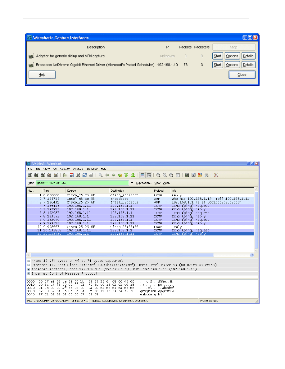
c. Click the Start button for the local area network interface adapter with IP address 192.168.1.10.
21
d. Generate some traffic from PC-B (192.168.1.11) to R1 interface Fa0/1 (192.168.1.1) using ping. This
traffic will go from S2 port Fa0/18 to S2 port Fa0/1 across the trunk link to S1 port Fa0/1 and then exit
interface Fa0/5 on S1 to reach R1.
PC-B:\>ping 192.168.1.1
e. Observe the results in Wireshark on PC-A. Notice the initial ARP request broadcast from PC-B (Intel
NIC) to determine the MAC address of the R1 Fa0/1 interface with IP address 192.168.1.1 and the
ARP reply from the R1 Cisco Ethernet interface. After the ARP request, the pings (echo request and
replies) can be seen going from PC-B to R1 and from R1 to PC-B through the switch.
Note: Your screen should look similar to the one below. Some additional packets might be captured
in addition to the pings, such as the R1 Fa0/1 LOOP reply.
Step 5: Monitor switch S1 port Fa0/5 SuperScan activity using Wireshark on PC-A.
a. If SuperScan is not on PC-B, download the SuperScan 4.0 tool from the Scanning Tools group at
. Unzip the file into a folder. The SuperScan4.exe file is executable and
installation is not required.
22
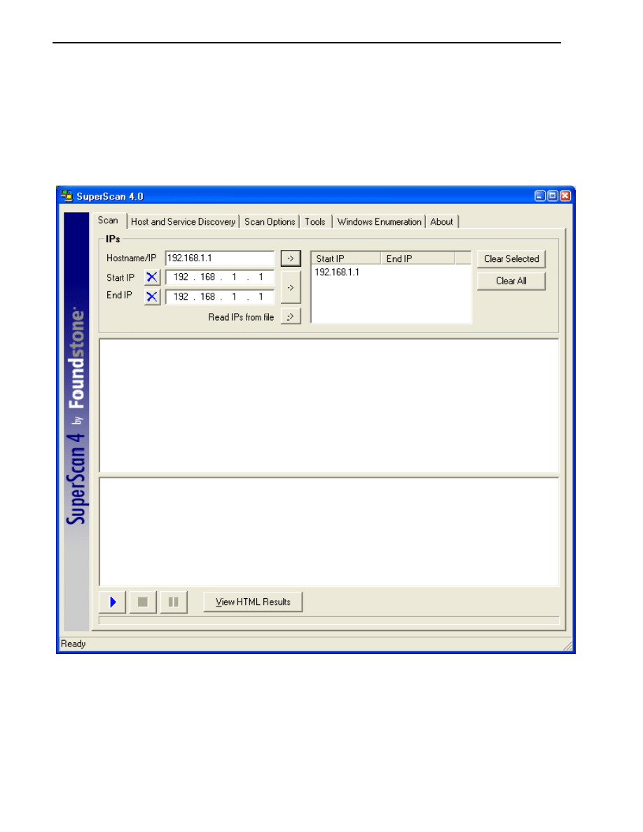
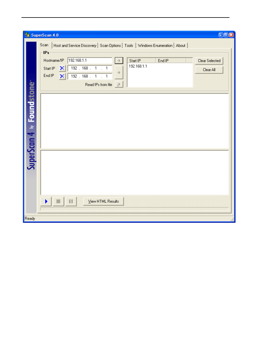
b. Start the SuperScan program on PC-B. Click the Host and Service Discovery tab. Check the
Timestamp Request check box, and uncheck the Echo Request check box. Scroll through the UDP
and TCP port selection lists and notice the range of ports that will be scanned.
c. In the SuperScan program, click the Scan tab and enter the IP address R1 FA0/1 (192.168.1.1) in the
Hostname/IP field.
d. Click the right arrow to populate the Start IP and End IP fields.
e. Clear the previous capture in Wireshark and start a new capture by clicking Capture > Start. When
prompted, click the Continue without saving button.
f.
In the SuperScan program, click the blue arrow button in the lower left to start the scan.
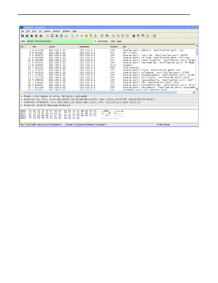
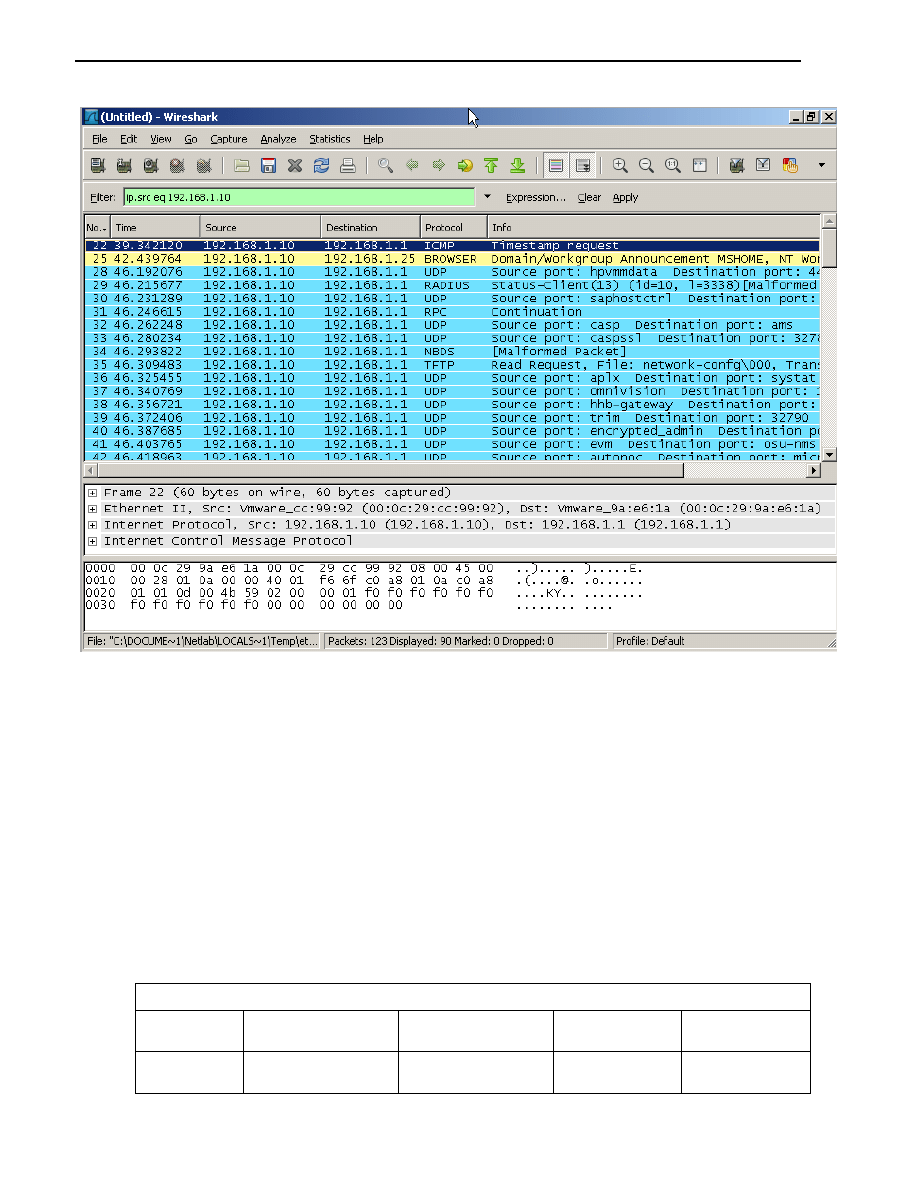
g. Observe the results in the Wireshark window on PC-A. Notice the number and types of ports tried by
the simulated SuperScan attack from PC-B (192.168.1.11) to R1 Fa0/1 (192.168.1.1). Your screen
should look similar to the following:
23
Task 2: Option 2 - Configure a SPAN Session Using NETLAB+ Remote
Equipment.
Note: This portion of the lab has been rewritten to enhance compatibility with the NETLAB+
system.
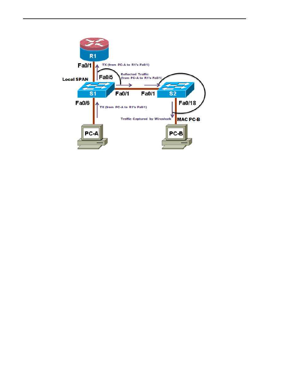
On switch S1, you will configure a local SPAN to reflect the traffic exiting Port Fa0/5, in this case, the traffic
from PC-A to R1’s Fa0/1. This traffic should be received by switch S2, and forwarded to PC-B, where
Wireshark is capturing the packets. Refer to the following diagram which illustrates the SPAN traffic flow.
Note: To perform this Task, Wireshark should be installed on PC-B.
24
Note: Switch S2 is acting as a regular switch, forwarding frames based on destination MAC addresses and
switch ports. The traffic entering S2 through Port Fa0/1 utilizes the R1’s MAC address as destination for the
Ethernet frame, therefore in order to forward those packets to PC-B, the R1’s MAC address must be the same
as PC-B. To accomplish this, R1’s Fa0/1 MAC address is modified using the IOS CLI to simulate PC-B’s MAC
address. This requirement is specific to the NETLAB+ environment.
Step 1: Configure a SPAN session on S1 with Source and Destination:
a. Return the Fa0/1 on S1 and S2 to its default configuration. This link S1 Fa0/1 to S2 Fa0/1 is going to
be used to carry the traffic being monitored.
S1(config)#default interface fastethernet 0/1
S2(config)#default interface fastethernet 0/1
b. Write down the MAC address for PC-B
PC-B’s MAC Address: ___________________________
PC-B’s MAC Address in this example is 000c-299a-e61a
c. Configure the PC-B’s MAC address on R1’s Fa0/1.
R1(config)#interface fa0/1
R1(config-if)#mac-address 000c.299a.e61a
d. Set the SPAN Source Interface using the monitor session command in global configuration mode.
The following configures a SPAN source port on fastethernet0/5 for egress traffic. Traffic copied on
the source port can be ingress only, egress only or both. In this case, the egress traffic is the only one
analyzed. On Switch S1 port Fa0/5 is connected to router R1 so traffic to the switch port Fa0/5 to R1
will be monitored.
S1(config)#monitor session 1 source interface fa0/5 tx

25
Note: The source can be a single interface, a range of interfaces, a single VLAN, or range of VLANs.
e. Set the SPAN destination interface.
S1(config)#monitor session 1 destination interface fa0/1
All egress traffic from S1 Fa0/5, where R1 is connected, will be copied to the SPAN destination port
Fa0/1, where PC-B with WireShark is connected.
Note: The destination can be an interface or a range of interfaces.
Step 2: Verify the setup of the SPAN session on S1.
Confirm the SPAN session setup using the show monitor session 1 command.
S1#show monitor session 1
Session 1
---------
Type : Local Session
Source Ports :
TX Only : Fa0/5
Destination Ports : Fa0/1
Encapsulation : Native
Ingress : Disabled
Step 3: (Optional) Download and install Wireshark on PC-B
a. WireShark is a network protocol analyzer (also called a packet sniffer) that runs with Windows XP
and Vista. If WireShark is not currently available on PC-B, you may download the latest version from
http://www.wireshark.org/download.html
and install it as described in Part 4, Task 1, Step 3.
Step 4: Monitor Switch S1 port Fa0/5 ping activity using Wireshark on PC-B
a. If WireShark is available, start the application.
b. From the main menu, select Capture > Interfaces.
c. Click the Start button for the Local area network interface adapter.
d. Generate some traffic from PC-A (192.168.1.10) to R1 interface Fa0/1 (192.168.1.1) using ping. This
traffic will go from S1 port Fa0/6 to S1 port Fa0/5. In addition, the traffic going from PC-A to R1
interface Fa0/1 is forwarded across the link between S1 and S2, and then S2 will forward this traffic to
PC-B, where Wireshark is capturing the packets. Before pinging, delete the ARP table on PC-A, so
an ARP request would be generated. Note that the SPAN session is configured only on S1, and S2 is
operating as a normal switch.
C:\>arp –d *
C:\>ping 192.168.1.1
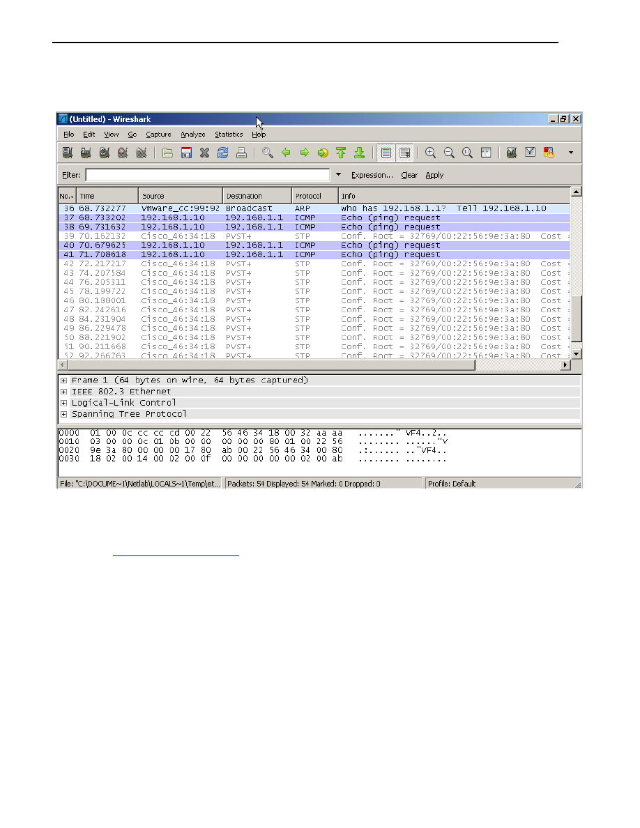
e. Observe the results in WireShark on PC-B. Notice the initial ARP request broadcast from PC-A to
determine the MAC address of the R1 Fa0/1 interface with IP address 192.168.1.1 and the ARP reply
from the R1 Cisco Ethernet interface. After the ARP request the pings (echo requests) can be seen
going from PC-A to R1 through the switch.
26
Note: Your screen should look similar to the one below. There may be some addition packets captured,
in addition to the pings, such as the R1 Fa0/1 LOOP Reply and Spanning Tree Packets.
Step 5: Monitor Switch S1 port Fa0/5 SuperScan activity using Wireshark on PC-B
a. If SuperScan is not on PC-A, download the SuperScan 4.0 tool from the Scanning Tools group at
. Unzip the file into a folder. The SuperScan4.exe file is executable and
installation is not required.
b. Start the SuperScan program on PC-A. Click the Host and Service Discovery tab. Check the
Timestamp Request check box and uncheck the Echo Request check box. Scroll the UDP and TCP
port selection lists and notice the range of ports that will be scanned.
c. In the SuperScan program click the Scan tab and enter the IP address of R1 FA0/1 (192.168.1.1) in
the Hostname/IP field.
d. Click the right facing arrow to populate the Start and End IP fields.
27
e. Clear the previous capture in WireShark and start a new capture by clicking Capture > Start and
when prompted click the Continue without saving button.
f.
In the SuperScan program click the button which is in the lower left of the screen, with the blue arrow
on it, to start the scan.
g. Observe the results on the WireShark window on PC-B. Notice the number and types of ports tried by
the simulated SuperScan attack from PC-A (192.168.1.11) to R1 Fa0/1 (192.168.1.1). Your screen
should look similar the following:
28
Step 6: Reflection.
a. Why should port security be enabled on switch access ports?
________________________________________________________________________________
________________________________________________________________________________
b. Why should port security be enabled on switch trunk ports?
________________________________________________________________________________
________________________________________________________________________________
c. Why should unused ports on a switch be disabled?
________________________________________________________________________________
________________________________________________________________________________
Router Interface Summary Table
Router Interface Summary
Router Model
Ethernet Interface
#1
Ethernet Interface
#2
Serial Interface
#1
Serial Interface
#2
1700
Fast Ethernet 0
(FA0)
Fast Ethernet 1
(FA1)
Serial 0 (S0)
Serial 1 (S1)
29
Router Interface Summary
1800
Fast Ethernet 0/0
(FA0/0)
Fast Ethernet 0/1
(FA0/1)
Serial 0/0/0
(S0/0/0)
Serial 0/0/1
(S0/0/1)
2600
Fast Ethernet 0/0
(FA0/0)
Fast Ethernet 0/1
(FA0/1)
Serial 0/0 (S0/0)
Serial 0/1 (S0/1)
2800
Fast Ethernet 0/0
(FA0/0)
Fast Ethernet 0/1
(FA0/1)
Serial 0/0/0
(S0/0/0)
Serial 0/0/1
(S0/0/1)
Note: To find out how the router is configured, look at the interfaces to identify the type of router
and how many interfaces the router has. There is no way to effectively list all the combinations of
configurations for each router class. This table includes identifiers for the possible combinations of
Ethernet and Serial interfaces in the device. The table does not include any other type of interface,
even though a specific router may contain one. An example of this might be an ISDN BRI interface.
The string in parenthesis is the legal abbreviation that can be used in Cisco IOS commands to
represent the interface.
Document Outline
- Background
- Step 1: Cable the network as shown in the topology.
- Step 2: Configure basic settings for the router and each switch.
- Step 3: Configure PC host IP settings.
- Step 4: Verify basic network connectivity.
- Step 5: Save the basic configurations for the router and both switches.
- Step 1: Configure a domain name.
- Step 2: Configure a privileged user for login from the SSH client.
- Step 3: Configure the incoming vty lines.
- Step 4: Generate the RSA encryption key pair for the router.
- Step 5: Verify the SSH configuration.
- Step 6: Configure SSH timeouts and authentication parameters.
- Step 7: Save the running-config to the startup-config.
- Step 1: (Optional) Download and install an SSH client on PC-A and PC-B.
- Step 2: Verify SSH connectivity to S1 from PC-A.
- Step 3: Save the configuration.
- Step 1: Configure switch S1 as the root switch.
- Step 2: Configure trunk ports on S1 and S2.
- Step 3: Change the native VLAN for the trunk ports on S1 and S2.
- Step 4: Prevent the use of DTP on S1 and S2.
- Step 5: Verify the trunking configuration on port Fa0/1.
- Step 6: Enable storm control for broadcasts.
- Step 7: Verify your configuration with the show run command.
- Step 1: Disable trunking on S1 access ports.
- Step 1: Enable PortFast on S1 and S2 access ports.
- Step 2: Enable BPDU guard on the S1 and S2 access ports.
- Step 3: (Optional) Enable root guard.
- Step 1: Record the R1 Fa0/0 MAC address.
- Step 2: Configure basic port security.
- Step 3: Verify port security on S1 Fa0/5.
- Step 4: Clear the S1 Fa0/5 error disabled status.
- Step 5: Remove basic port security on S1 Fa0/5.
- Step 6: (Optional) Configure port security for VoIP.
- Step 7: Disable unused ports on S1 and S2.
- Step 8: (Optional) Move active ports to a VLAN other than the default VLAN 1
- Note: Option 1 assumes you have physical access to the devices shown in the topology for this lab. NETLAB+ users accessing lab equipment remotely should proceed to Task 2: Option 2.
- Step 1: Configure a SPAN session on S1 with a source and destination
- Step 3: (Optional) Download and install Wireshark on PC-A.
- Step 4: Monitor switch S1 port Fa0/5 ping activity using Wireshark on PC-A.
- Step 5: Monitor switch S1 port Fa0/5 SuperScan activity using Wireshark on PC-A.
- Note: This portion of the lab has been rewritten to enhance compatibility with the NETLAB+ system.
- Step 1: Configure a SPAN session on S1 with Source and Destination:
- Step 3: (Optional) Download and install Wireshark on PC-B
- Step 4: Monitor Switch S1 port Fa0/5 ping activity using Wireshark on PC-B
- Step 5: Monitor Switch S1 port Fa0/5 SuperScan activity using Wireshark on PC-B
Wyszukiwarka
Podobne podstrony:
BST L2 id 93597 Nieznany
BST L7a id 93600 Nieznany (2)
BST L5 Teoria id 93599 Nieznany (2)
Abolicja podatkowa id 50334 Nieznany (2)
4 LIDER MENEDZER id 37733 Nieznany (2)
katechezy MB id 233498 Nieznany
metro sciaga id 296943 Nieznany
perf id 354744 Nieznany
interbase id 92028 Nieznany
Mbaku id 289860 Nieznany
Probiotyki antybiotyki id 66316 Nieznany
miedziowanie cz 2 id 113259 Nieznany
LTC1729 id 273494 Nieznany
D11B7AOver0400 id 130434 Nieznany
analiza ryzyka bio id 61320 Nieznany
pedagogika ogolna id 353595 Nieznany
Misc3 id 302777 Nieznany
więcej podobnych podstron