V1.2
LIB-319
WIRELESS RECEIVER
INSTALLATION MANUAL
Libeei04.qxd 4/11/2002 9:36 AM Page i

1
TABLE OF CONTENTS
INTRODUCTION . . . . . . . . . . . . . . . . . . . . . . . . . . . . . . . . . . . . . . . . . . . . . . . . . . . . . .2
1.1 About Paradox . . . . . . . . . . . . . . . . . . . . . . . . . . . . . . . . . . . . . . . . . . . . . . . . . . . . .2
1.2 Technical Specifications . . . . . . . . . . . . . . . . . . . . . . . . . . . . . . . . . . . . . . . . . . . . . .3
1.3 System Features . . . . . . . . . . . . . . . . . . . . . . . . . . . . . . . . . . . . . . . . . . . . . . . . . . .3
INSTALLATION . . . . . . . . . . . . . . . . . . . . . . . . . . . . . . . . . . . . . . . . . . . . . . . . . . . . . . .5
2.1 Location & Mounting . . . . . . . . . . . . . . . . . . . . . . . . . . . . . . . . . . . . . . . . . . . . . . . . .5
2.2 Power Connections . . . . . . . . . . . . . . . . . . . . . . . . . . . . . . . . . . . . . . . . . . . . . . . . .5
2.3 Zone Output Wiring . . . . . . . . . . . . . . . . . . . . . . . . . . . . . . . . . . . . . . . . . . . . . . . . .7
2.4 Connecting Keypads . . . . . . . . . . . . . . . . . . . . . . . . . . . . . . . . . . . . . . . . . . . . . . . . .7
2.5 Hand-Held Remote Controls . . . . . . . . . . . . . . . . . . . . . . . . . . . . . . . . . . . . . . . . . . .8
PROGRAMMING . . . . . . . . . . . . . . . . . . . . . . . . . . . . . . . . . . . . . . . . . . . . . . . . . . . . . .9
3.1 Installer Code . . . . . . . . . . . . . . . . . . . . . . . . . . . . . . . . . . . . . . . . . . . . . . . . . . . . . .9
3.2 Installer Lock . . . . . . . . . . . . . . . . . . . . . . . . . . . . . . . . . . . . . . . . . . . . . . . . . . . . . .9
3.3 System Reset . . . . . . . . . . . . . . . . . . . . . . . . . . . . . . . . . . . . . . . . . . . . . . . . . . . . .10
ASSIGNING DETECTORS & DOOR CONTACTS . . . . . . . . . . . . . . . . . . . . . . . . . . . .11
4.1 Automatic (Plug & Play) Zone Assignment . . . . . . . . . . . . . . . . . . . . . . . . . . . . . . . .11
4.2 Force Zone Assignment . . . . . . . . . . . . . . . . . . . . . . . . . . . . . . . . . . . . . . . . . . . . .12
4.3 Switch Zone Assignment . . . . . . . . . . . . . . . . . . . . . . . . . . . . . . . . . . . . . . . . . . . . .13
4.4 View Transmitter Serial Numbers . . . . . . . . . . . . . . . . . . . . . . . . . . . . . . . . . . . . . .14
4.5 Erase Specific Zone . . . . . . . . . . . . . . . . . . . . . . . . . . . . . . . . . . . . . . . . . . . . . . . .14
4.6 Zone Output State . . . . . . . . . . . . . . . . . . . . . . . . . . . . . . . . . . . . . . . . . . . . . . . . .15
REMOTE CONTROL ASSIGNMENT . . . . . . . . . . . . . . . . . . . . . . . . . . . . . . . . . . . . . .16
5.1 Automatic Remote Control Assignment . . . . . . . . . . . . . . . . . . . . . . . . . . . . . . . . . .16
5.2 View Remote Control Serial Numbers . . . . . . . . . . . . . . . . . . . . . . . . . . . . . . . . . . .17
5.3 Erase Remote Control Assignment . . . . . . . . . . . . . . . . . . . . . . . . . . . . . . . . . . . . .18
5.4 Program Outputs 7 to 9 . . . . . . . . . . . . . . . . . . . . . . . . . . . . . . . . . . . . . . . . . . . . .18
SUPERVISION FEATURES . . . . . . . . . . . . . . . . . . . . . . . . . . . . . . . . . . . . . . . . . . . . .19
6.1 Low Battery Supervision . . . . . . . . . . . . . . . . . . . . . . . . . . . . . . . . . . . . . . . . . . . . .19
6.2 Check-In Supervision . . . . . . . . . . . . . . . . . . . . . . . . . . . . . . . . . . . . . . . . . . . . . . .20
6.2.1 Check-In Timer . . . . . . . . . . . . . . . . . . . . . . . . . . . . . . . . . . . . . . . . . . . . . . . . . .21
6.3 Transmitter Tamper Supervision . . . . . . . . . . . . . . . . . . . . . . . . . . . . . . . . . . . . . . .21
6.4 Receiver Tamper Supervision . . . . . . . . . . . . . . . . . . . . . . . . . . . . . . . . . . . . . . . . .22
6.5 Trouble Display Mode . . . . . . . . . . . . . . . . . . . . . . . . . . . . . . . . . . . . . . . . . . . . . . .23
6.6 Trouble Memory . . . . . . . . . . . . . . . . . . . . . . . . . . . . . . . . . . . . . . . . . . . . . . . . . . .24
6.7 Beep On Trouble . . . . . . . . . . . . . . . . . . . . . . . . . . . . . . . . . . . . . . . . . . . . . . . . . .24
6.8 Signal Strength Indicator Mode . . . . . . . . . . . . . . . . . . . . . . . . . . . . . . . . . . . . . . . .25
Libeei04.qxd 4/11/2002 9:36 AM Page 1

2
3
range of "intelligent" and easy to use control panels, efficient peripheral security
devices, or "false alarm free" detectors. We continuously put all our resources into
developing products that reflect our twin philosophies of innovation and user-
friendliness. Now we invite you to reap the benefits.
1.2 Technical Specifications
- Manchester Decoding
- Diversity Antenna
- Error Detection & Correction
- Frequency:
902MHz-928MHz
- Range (line of sight):
1000m (3280ft.)
- Outputs: 12
- Service Keypad:
Yes
- Data Rate:
10KB/s
- Sensitivity: -105dBm
- Current:
70mA
- Dimension (without antenna):
6”H x 6.5”L x 1.1”W
- Operating Temperature:
0°C - 50°C (32°F - 122°F)
- Operating Humidity:
85%
- Zone Output Current:
30mA
1.3 System Features
• Reflow Design
• No Tuned Circuit
• Tamper Switch
• Service Keypad Programming
• 12 zone outputs (Active Low)
• Plug & Play, Force and Switch Zone Assignment Modes
• Low Battery, Check-In and Tamper Supervision
• Trouble Indicator Mode
• Trouble Memory
• Beep on Trouble
• Signal Strength Indicator Mode
INTRODUCTION
Paradox is proud to introduce the Liberator wireless system. The Liberator system
consists of an RF Receiver that can support up to 12 wireless transmitters (motion
detectors and contact switches) and 12 remote controls, in conjunction with any
Paradox Series control panel and with most other brands of control panels. Fully
supervised, this system will provide the reliability of a traditional hard-wired system
with the following advantages:
• Quick & simple installation
• Cost reduction due to ease of installation
• Minimal damage to property due to installation
• Also ideal for temporary installations
The wireless transmitters are battery operated and are programmed to send the
following types of status signals to the receiver: zone open, zone restore, low
battery, battery restore, tamper open and tamper restore. When a transmitter sends
a signal, the receiver processes the signal, displays it on the keypad and toggles the
appropriate zone output. If one of the receiver’s twelve zone outputs is connected
to a control panel input; when the output is toggled, the control panel will generate
an alarm. The transmitters are also programmed to periodically send a check-in
signal to confirm their presence and functionality. If the receiver does not receive
any type of signal during the specified check-in period, it will display a check-in
trouble and can optionally toggle a zone output indicating a transmitter problem.
1.1 About Paradox
Paradox Security Systems strives to design and manufacture the best security
products money can buy. Our products are of the highest quality standards and
most importantly meet the needs and expectations of our customers.
By refusing to settle for the limitations of existing technology, Paradox makes it
clear, we are not interested in mirroring the products already on the market.
Breaking down barriers to better technology is what innovation is all about.
The guiding principle behind Paradox research and development has always been
to create security products that make sense. Whether the situation calls for a full
Libeei04.qxd 4/11/2002 9:36 AM Page 2

4
5
INSTALLATION
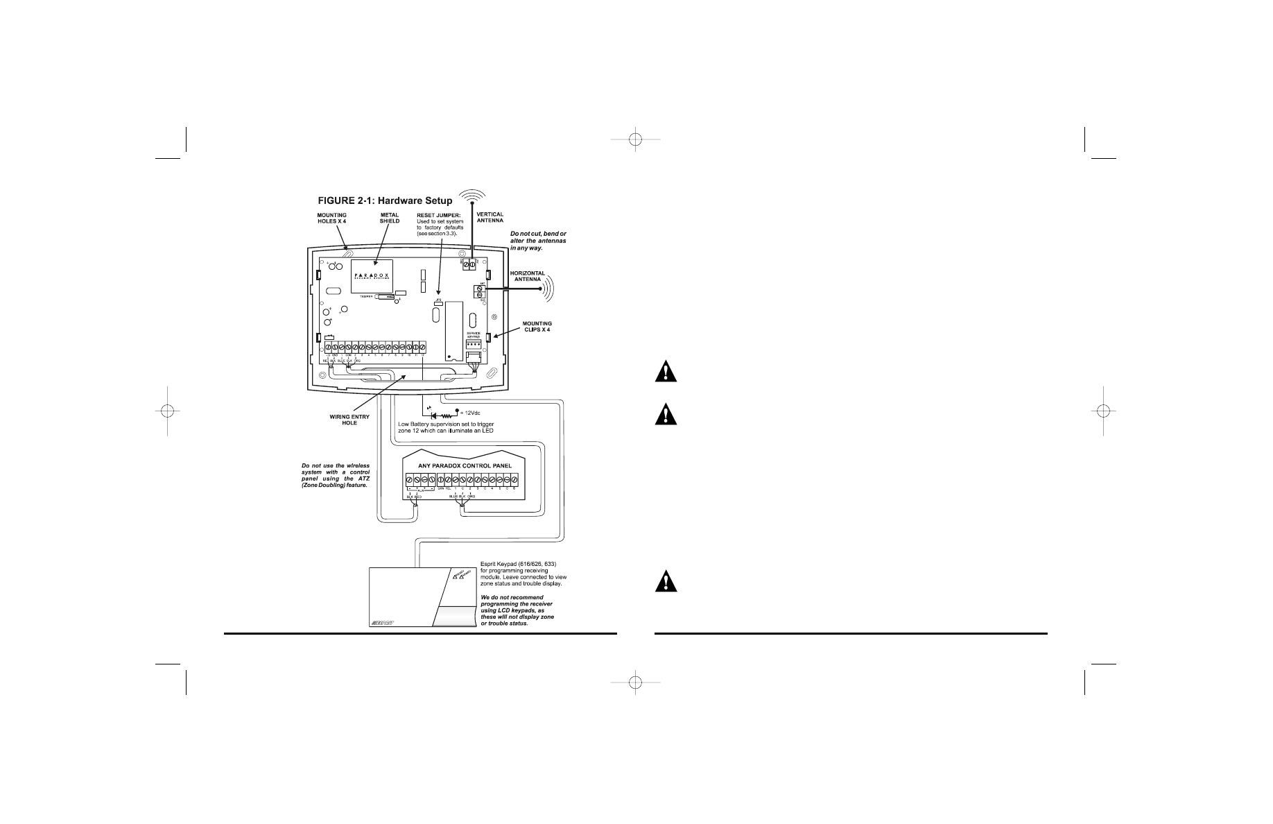
2.1 Location & Mounting
Mount the "receiver" on a wall, leaving at least 50mm (2") around the panel box to
permit adequate ventilation/heat dissipation. Select a site that is not susceptible to
drastic changes in temperature and avoid installing the receiving module near or in
the path of strong RF fields, such as neon lights or computers. Also avoid installing
the receiver on or near metal objects, circuit breaker boxes, air conditioners and
heater ducts. As these devices may cause interference, reducing the receiver's
sensitivity. We recommend installing the receiver in a centralized location on the main
floor, avoid installing the receiver in the basement. When selecting an installation site
please take into consideration that the maximum reception distance of the receiver is
1000m/3280ft. in line of sight. To avoid interference, install the transmitters a
minimum of 1.5 meters (5 feet) away from the receiver.
Do not cut, bend or alter the antennas or mount the receiver near or on metal
as this may affect the sensitivity of the receiver!
Firmly screw the two antennas into the connectors marked "
ANT
" on the receiver as
shown in figure 2-1. Using a drill or screwdriver, punch out the four mounting holes
on the back plastic case. Align the six holes of the printed circuit board with the six
pins on the back plastic mounting case and snap into place (see figure 2-1). If
placed correctly, the antennas will lean directly over the groves in the mounting
case. After completing wiring as detailed in sections 2.2 to 2.4, run the wires
through the entry hole on the back plastic case and screw the back of the plastic
case onto the selected installation site. After programming and wiring the receiving
module, affix the plastic cover and screw into place.
2.2 Power Connections
The receiver may be powered by the auxiliary terminals (12V
DC
) of the control panel.
Simply connect the "
AUX
+" terminal of the control panel to the "+12" terminal of the
receiver and the "
AUX
-" of the control panel to the "
GND
" of the receiver (see figure 2-
1). If using an external power source please ensure that the "
GND
" of the receiver
and the power source are connected to the "
AUX
-" terminal of the control panel.
Liberator Wireless Motion Detector (LIB-474B):
• Dual Element Sensor
• Auto Pulse Signal Processing (Patented)
• Auto Temperature Compensation
• "No Dead Zone" Standard Lens
• LED Indicators for Detection (red) & Low Battery (yellow)
• Built-in Antenna
• Tamper Switch
• One 9V Alkaline Battery
Liberator Wireless Contact Switch (LIB-400B):
• Dual High Sensitivity Reed Switch
• External Switch Transmission (Normally Closed)
• Low Battery LED Indicator (yellow)
• Built-in Antenna
• Tamper Switch
• Three 1.5V “AAA” Alkaline Batteries
Liberator 4-Button Remote Control (LIB-349):
• Water Resistant
• Range: 30m (100ft.)
• Two 3V Lithium batteries (CR2016)
• Battery Life: Apprx. 1 to 2 years
• Power Transmission: 5mW
• Current Consumption: 18mA (transmission)
Libeei04.qxd 4/11/2002 9:36 AM Page 4
6
7
2.3 Zone Output Wiring
The LIB-319 is not a stand-alone alarm system, it must be used in conjunction
with another control panel. If you wish to generate an alarm when the output on the
receiver is toggled, connect the receiver’s zone outputs directly to the control panel
inputs and the "
COM
" terminal of the receiver to the "
COM
" terminal of the control
panel as shown in figure 2-1. Alternatively, the receiver's zone outputs can be
connected to another device such as an LED or relay. When a transmitter
generates an alarm condition, it will send a signal to the receiver which will toggle
the appropriate zone output and if the receiver’s zone outputs are connected to the
control panel inputs, the control panel will generate an alarm. The receiver may also
toggle the receiver’s zone output if the transmitter sends a trouble signal (i.e. low
battery), which the receiver has been programmed to supervise (see Supervision
Features in section 6).
EOL resistors are not incorporated into the receiver’s zone outputs. If your
installation requires the use of EOL resistors, they must be added to the
receiver’s zone outputs
The Paradox ATZ (Zone Doubling) feature will not function with the wireless
system.
2.4 Connecting Keypads
To program the receiver, you must connect a service keypad (616, 626, 633, 636 or
646) to the receiver. The keypad connected to the control panel will not display any
trouble conditions nor can it be used to program the receiver. The control panel
keypad will only display zone status if the receiver’s zone output has been wired to
a control panel’s input as described in section 2.3. Using a keypad with a serial
connector, connect the keypad to the serial terminal on the receiver labeled "service
keypad" (see figure 2-1). The receiver’s keypad will allow you to view the receiver’s
trouble status (see Trouble Display Mode in section 6.5) and zone status.
We do not recommend programming the receiver using LCD keypads, as
these will not correctly display programming, zone or trouble status.
2.5 Hand-Held Remote Controls
Libeei04.qxd 4/11/2002 9:36 AM Page 6
PROGRAMMING
To program the “Liberator” a keypad must be connected to the serial terminal
marked "service keypad" on the receiver. The keypad connected to the control
panel can not be used to program the receiver or use any of its modes. To program
any data or information into the receiver's addresses, you must first enter the
programming mode.
After entering the programming mode, enter the 3-digit address of the feature or option
you would like to program. Then enter the required data for that particular address as
defined by the programming card and the corresponding section in this manual.
3.1 Installer Code
Addresses 000 to 002 - Default: 747474
The installer code is used to enter the receiver's programming mode, which allows
you to program all the features, options and commands of the wireless system. The
installer code is 6 digits in length and each digit can be any value from 0-9. If you
wish to change the installer code press:
[
ENTER
] + current Installer Code + [0] [0] [0] + first 2 digits of new code + [0] [0]
[1] + next 2 digits of new code + [0] [0] [2] + final 2 digits of new code + [
ENTER
]
3.2 Installer Lock
Address 020; [1] [4] [7]
Lock: Program 147 into address 020 to lock out any system resets. Hence,
performing a hardware reset (see section 3.3) will not affect the current settings.
Unlock: To remove the installer lock, program any 3-digit value other than 147 into
address 020.
To enter the programming mode, press:
[
ENTER
] + Installer Code
8
9
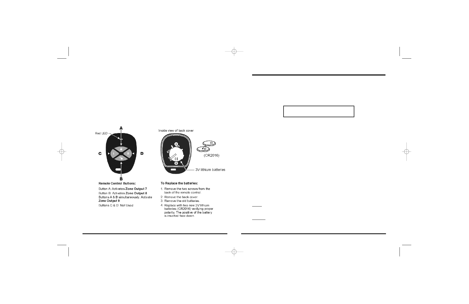
The LIB-319 also supports the use of up to twelve remote controls. Whenever one
or more remote controls are assigned to the Liberator (see section 5.1), the receiver
reserves outputs 7 to 9 for the remote controls. These outputs are activated by
pressing a specific button on assigned remote controls as shown in Figure 2.
Please note that the same button on all remote controls will activate the same
output. For example, if 5 remote controls have been assigned, pressing button B on
any of the 5 remote controls will activate Zone Output 8.
These remote controls can transmit a signal up to a maximum of 30 meters (100ft).
The remote controls are powered by two 3V lithium batteries. Occasionally this
battery must be changed as shown in figure 2.
Figure 2: Remote Control
Libeei04.qxd 4/11/2002 9:36 AM Page 8

10
11
ASSIGNING DETECTORS & DOOR CONTACTS
In order to trigger the receiver’s zone outputs, each transmitter must be assigned to
an available (empty) zone output. Every time the tamper switch on a transmitter is
pressed, it will send its serial number to be registered in the selected zone output.
4.1 Automatic (Plug & Play) Zone Assignment
For U.S. versions, please refer to shaded box on the following page
[
ENTER
] + Installer Code + [
MEM
] + [1]
The receiver can be set to automatically assign transmitters to the receiver’s zone
outputs in chronological order. After entering this mode, the [
ENTER
] and [
MEM
] keys
will flash to indicate that you can remain in this mode until you have completed all
required zone assignments. The keypad will display the zones that have already
been assigned by illuminating the corresponding key. Any unlit keys represent zone
outputs that have not been assigned a transmitter or have been reserved (see
Supervision Features in section 6 or Remote Control Assignment in section 5).
When the tamper switch on a transmitter is pressed, the receiver will search for the
first unused zone output (1 to 12) and assign the transmitter’s serial number to that
zone (illuminating the corresponding key). To exit the Automatic Zone Assignment
Mode, press the [
ENTER
] or [
CLEAR
] key.
Example: Two transmitters are being added to an installation consisting of four
transmitters, which have been assigned zones 1 through 4. Set the receiver in
Automatic Zone Assignment Mode by pressing [
ENTER
] + Installer Code + [
MEM
] +
[1]. The [
ENTER
] and [
MEM
] keys will flash and keys [1] through [4] will be lit to
indicate transmitters have been assigned to these zone outputs. When the tamper
switch on one of the additional transmitters is pressed, the receiver will
automatically program the transmitter into the next unused zone output, that being
zone output 5. Press the tamper switch on the following additional transmitter and
the receiver will program the transmitter's serial number into zone output 6. The [5]
and [6] keys will illuminate to indicate successful zone assignment.
To enter a zone assignment mode, press:
[
ENTER
] + Installer Code + [
MEM
] + available Modes will flash (see below)
3.3 System Reset
Performing a system reset will set all addresses including the installer code to
factory default. The installer code will reset to 747474, all keys in address 014 will
reset to off. Address 010, 012 and the current zone assignments will not be
affected. To execute a system reset perform the following:
1) Make sure the installer lock is disabled (see section 3.2).
2) Remove the power connections ("+12" & "
GND
") from the receiver.
3) Place a jumper on the reset pins (JP3) of the receiver.
4) Re-connect the power connections to the receiver.
5) Wait 10 seconds and remove the jumper.
Libeei04.qxd 4/11/2002 9:36 AM Page 10
4.2 Force Zone Assignment
For U.S. versions, please refer to shaded box on the following page
[
ENTER
] + Installer Code + [
MEM
] + [2]
The Force Assignment Mode allows you to assign a transmitter to a specific zone
output. After entering this mode, the [
ENTER
] and [
MEM
] keys will flash to indicate that
you can remain in this mode until you have completed all required zone assign-
ments. The keypad will display the zone outputs that have already been assigned
by illuminating the corresponding key. Any unlit keys represent zone outputs that
have not been assigned. Press the key corresponding to the zone output you wish
to program, the key will flash to indicate that it is ready to receive data. Press the
tamper switch on the transmitter to program the serial number into the selected
zone output. The key will remain lit to indicate that the serial number has been
saved and assigned to the selected zone.
Please note, the Force Assignment Mode will not overwrite an existing zone
assignment, if you wish to do so you must first erase it (see section 4.5) or
switch the zone assignment with an empty zone (see section 4.3).
Automatic Zone Assignment for U.S. Versions Only
[
ENTER
] + Installer Code + [
MEM
] + [1]
After entering this mode the [
ENTER
] key will turn on and the keypad will display
the zones that have already been assigned by illuminating the corresponding
key. Any unlit keys represent zone outputs that have not been assigned a
transmitter or have been reserved (see Supervision Features in section 6 or
Remote Control Assignment in section 5). Using the keypad, enter the 6-digit
serial number of the transmitter you wish to assign. After entering the final digit,
the receiver will search for the first unused zone output (1 to 12) and assign the
transmitter’s serial number to that zone illuminating the corresponding key. To
exit the Automatic Zone Assignment Mode, press the [
ENTER
] or [
CLEAR
] key.
Please note that the transmitter’s serial number can be located in its
compartment or by using the View Serial Number mode (see section 4.4 ). Also
note that you will receive a rejection beep if you enter a serial number that does
not exist or that has already been assigned to a zone output.
12
13
Example: A transmitter is being added to an installation consisting of four
transmitters, which have been assigned zone outputs 1-2 and zone outputs 5-6.
Keys [1], [2], [5] and [6] will be lit to indicate these zone outputs have been assigned
a transmitter. To assign the new transmitter to zone output 8, set the receiver in
Force Zone Assignment Mode by pressing [
ENTER
] + Installer Code + [
MEM
] + [2].
The [
ENTER
] and [
MEM
] keys will flash. Press the [8] key (key will flash) to select zone
output 8 and press the tamper switch on the transmitter to program its serial number
into zone output 8. The [8] key will remain illuminated to indicate that programming
was successful.
4.3 Switch Zone Assignment
[
ENTER
] + Installer Code + [
MEM
] + [3]
The Switch Zone Assignment Mode allows you to swap one zone assignment with
another. After entering this mode the [
ENTER
] and [
MEM
] keys will flash and the
keypad will display the zone outputs that have already been assigned, by
illuminating the corresponding key. Any unlit keys represent zone outputs that have
not been assigned. Press the key corresponding to the first zone output you wish
Force Zone Assignment for U.S. Versions Only
[
ENTER
] + Installer Code + [
MEM
] + [2]
After entering this mode the [
ENTER
] key will turn on and the keypad will display
the zones that have already been assigned by illuminating the corresponding
key. Any unlit keys represent zone outputs that have not been assigned a
transmitter or have been reserved (see Supervision Features in section 6 or
Remote Control Assignment in section 5). Using the keypad, enter the 6-digit
serial number of the transmitter you wish to assign. After entering the final digit,
the [
MEM
] and [
ENTER
] keys will flash. Press the key corresponding to the zone
output you wish to program, the key will remain lit to indicate that the serial
number has been saved and assigned to the selected zone. To exit the Force
Zone Assignment Mode, press the [
ENTER
] or [
CLEAR
] key.
Please note that the transmitter’s serial number can be located in its
compartment or by using the View Serial Number mode (see section 4.4 ). Also
note that you will receive a rejection beep if you enter a serial number that does
not exist or that has already been assigned to a zone output.
Libeei04.qxd 4/11/2002 9:36 AM Page 12
to switch (key will flash), followed by the key corresponding to the next zone output
you wish to switch. The receiver will automatically copy the serial number from one
zone output to the other and vice versa. Note that an assigned zone can be
switched with a zone that has not been assigned (empty).
In this mode the receiver will not receive any type of transmission.
Example: Transmitter A has been assigned zone 1 and transmitter B has been assigned
zone 4. You wish to switch transmitter A to zone 4 and transmitter B to zone 1. Set the
receiver in Switch Zone Assignment Mode by pressing [
ENTER
] + Installer Code + [
MEM
]
+ [3]. The [
ENTER
] and [
MEM
] keys will flash. Then press the [1] key (key will flash)
followed by the [4] key. Both keys will illuminate to indicate that transmitter A is now
assigned to zone 4 and transmitter B is now assigned to zone 1.
4.4 View Transmitter Serial Numbers
[
ENTER
] + Installer Code + [
MEM
] + [4]
This mode displays the serial number of the selected transmitter one digit at a time
by illuminating and extinguishing the key corresponding to the digit. If the
transmitter has already been assigned, the key corresponding to its zone output will
flash after displaying the serial number. After entering this mode, the [
ENTER
] and
[
MEM
] keys will flash. The keypad will display the zones that have already been
assigned by illuminating the corresponding key. Any unlit keys represent zone
outputs that have not been assigned a transmitter. To view the serial number of a
device that has been assigned, press one of the lit keys which correspond to an
assigned zone output. To view the serial number of a transmitter which hasn’t been
assigned press and release the transmitter’s tamper switch.
For example, serial number 135789 has been assigned to zone output 3. The
keypad will illuminate the [1] key, then the key will extinguish. This will continue for
each digit in the serial number [3], [5], [7], [8] and [9]. Then the [3] key will flash.
4.5 Erase Specific Zone
[
ENTER
] + Installer Code + [
MEM
] + [0]
An assigned zone can not be overwritten; you must first erase it in order to assign
a new transmitter to that zone. To clear a zone, enter the erase zone mode by
14
15
pressing [
ENTER
] + Installer Code + [
MEM
] + [10]. After entering this mode the
[
ENTER
] and [
MEM
] keys will flash and the keypad will display the zones that have
already been assigned, by illuminating the corresponding key. Any unlit keys
represent zones that have not been assigned. Press the key (must be lit)
corresponding to the zone you wish to erase. The key will extinguish to indicate the
zone assignment has been erased.
In this mode the receiver will not receive any type of transmission.
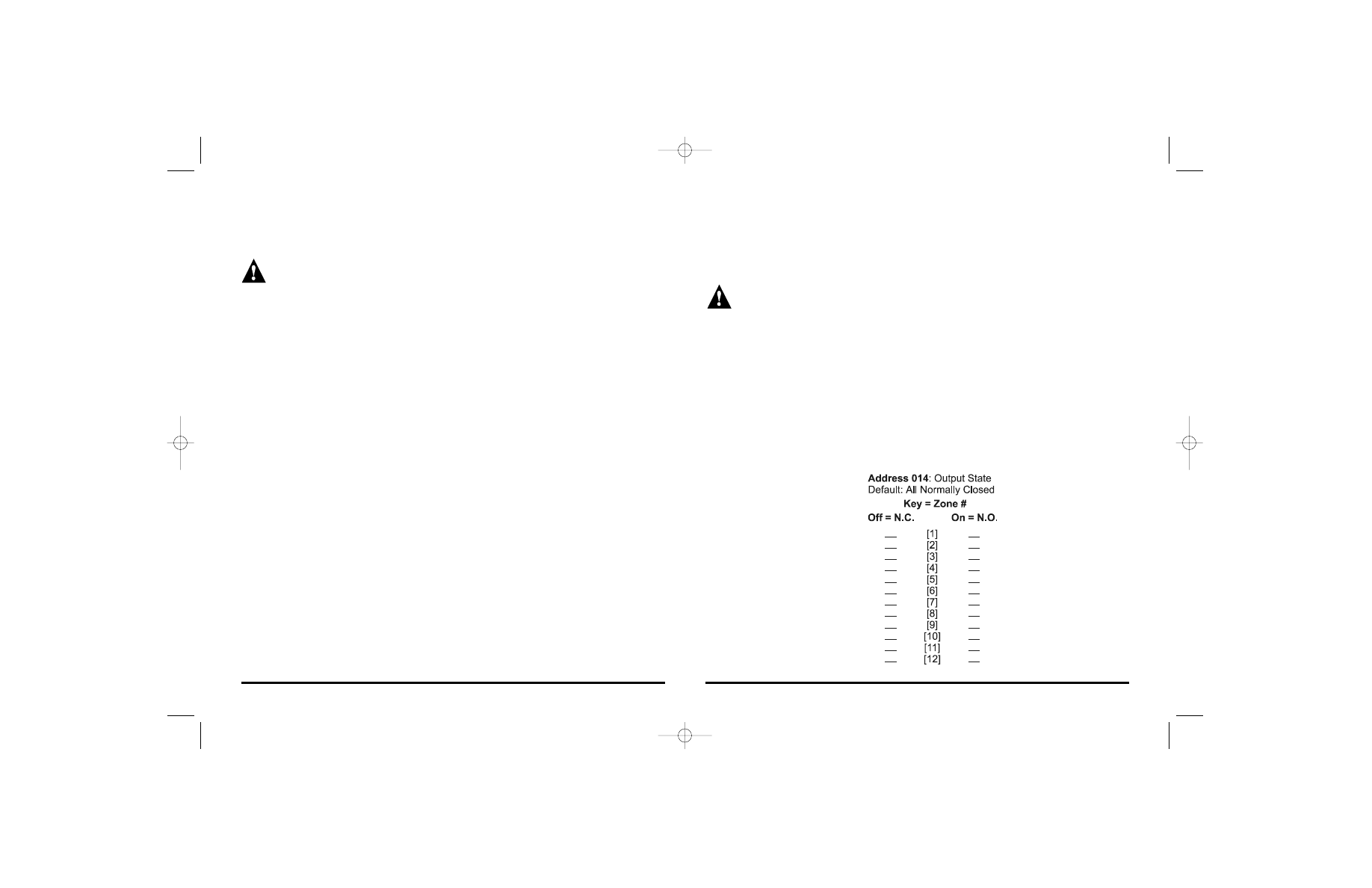
4.6 Zone Output State
Address 014; Keys [1] to [12] - Default: All Normally Closed
Once a transmitter has been assigned to a zone, you must define whether the
receiver’s zone output will be normally open or normally closed. In address 014
each key represents zone outputs 1 through 12. The associated zone output will be
normally closed if the key is off and if the key is on, the associated zone output will
be normally open. To do so press:
[
ENTER
] + Installer Code + [0] [1] [4] + On/Off status of keys [1] to [12] + [
ENTER
] to
accept or [
CLEAR
] to cancel.
Libeei04.qxd 4/11/2002 9:36 AM Page 14
5.2 View Remote Control Serial Numbers
[
ENTER
] + Installer Code + [
MEM
] + [6]
This mode displays the serial number of the selected remote control one digit at a
time by illuminating and extinguishing the key corresponding to the digit. If the
remote control has already been assigned, the key corresponding to the location of
the assigned remote control will flash after displaying the serial number. After
entering this mode, the [
ENTER
] and [
MEM
] keys will flash. The keypad will display
the remote controls that have already been assigned by illuminating the
corresponding key. Any unlit keys represent remote controls that have not been
assigned. To view the serial number of a device that has been assigned simply
press one of the lit keys which correspond to an assigned zone output. To view the
serial number of a remote control which hasn’t been assigned press and release
buttons A and B on the remote control (refer to section 2.5 on page 8).
For example, serial number 135789 has been assigned to location 3. The keypad
will illuminate the [1] key, then the key will extinguish. This will continue for each
digit in the serial number [3], [5], [7], [8] and [9]. Then the [3] key will flash.
Automatic Remote Control Assignment for U.S. Versions Only
[
ENTER
] + Installer Code + [
MEM
] + [5]
After entering this mode the [
ENTER
] key will turn on and the keypad will display
the remote controls that have already been assigned by illuminating keys [1] to
[12]. Please note that keys [1] to [12] represent the number of remote
controls that can be assigned, they do not represent the receiver’s zone
outputs. Any unlit keys represent remote controls that have not been assigned.
Using the keypad, enter the 6-digit serial number of the remote control you wish
to assign. After entering the final digit, the receiver will assign the remote control’s
serial number to the receiver (illuminating the corresponding key). To exit the
Automatic Zone Assignment Mode, press the [
ENTER
] or [
CLEAR
] key.
Please note that the remote control’s serial number can be located in its
compartment or by using the View Remote Control Serial Number mode (see
section 5.2). Also note that you will receive a rejection beep if you enter a serial
number that does not exist or that has already been assigned.
16
17
REMOTE CONTROL ASSIGNMENT
As soon as a remote control is assigned to the receiver, it will reserve zone outputs
7 to 9. These outputs are activated by pressing a specific button on any assigned
remote control as explained in section 2.5 on page 8.
When using the remote controls, users must press the button(s) until the red LED
on the remote control illuminates. This short delay (0.25 sec.) before sending a
signal is to avoid any accidental transmissions. After pressing and holding a button
continuously for five seconds, the remote control will no longer transmit any signals
until the button is released and pressed again.
After activating a LATCHED output (7, 8 or 9), the receiver will ignore signals
originating from the same button for two seconds. Pressing and holding the button
will continuously reset the timer. This delay is to avoid unwanted output deactivation.
When a receiver activates a TIMED output (7, 8 or 9), the receiver will start the
output’s assigned timer. If a button is pressed before the end of the timer, it will reset
the timer. Pressing and holding the button will continuously reset the timer.
5.1 Automatic Remote Control Assignment
For U.S. versions, please refer to shaded text box on the following page
[
ENTER
] + Installer Code + [
MEM
] + [5]
After entering this mode, the [
ENTER
] and [
MEM
] keys will flash to indicate that you
can remain in this mode until you have completed all required remote control
assignments. The keypad will display how many remote controls have been
assigned by illuminating keys [1] to [12]. Please note that keys [1] to [12]
represent the number of remote controls that can be assigned, they do not
represent the receiver’s zone outputs. Any unlit keys represent remote controls
that have not been assigned. When buttons A and B on a remote control are
pressed (refer to section 2.5 on page 8), the receiver will assign the remote control’s
serial number to the receiver (illuminating the corresponding key). To exit the
Automatic Remote Control Assignment Mode, press the [
ENTER
] or [
CLEAR
] key.
You will not be able to assign transmitters to zone outputs 7 to 9 if any remote
controls have been assigned. If a remote control is assigned after a transmitter
has already been assigned to a zone output, the receiver will erase the zone
assignment and enable the remote controls.
Libeei04.qxd 4/11/2002 9:36 AM Page 16
SUPERVISION FEATURES
6.1 Low Battery Supervision
Address 010; Keys [1] to [3]
The wireless transmitters function on two 3.6V Lithium batteries. When a transmitter
detects a battery voltage of 6.5V or less, it will transmit a signal to the receiver
indicating that the battery voltage is low. When the signal is received, the receiver
will display this trouble condition on the service keypad as described in section 6.5,
Trouble Display Mode. The yellow LED on the affected transmitter will begin to
flash. The receiver can also be programmed to respond to a low battery signal by
triggering zone 12 and/or by triggering the specific zone output from which the
signal originated. Please refer to the table below to set the desired features.
Trigger Zone Output 12:
The receiver reserves zone 12 to trigger every time a low battery is received from any
of the transmitters. If zone output 12 is connected to a zone input on the control panel,
the panel will then generate an alarm every time there is a low battery in the system.
Alternatively, the output can be connected to another device such as an LED or relay.
You will not be able to assign a transmitter to zone output 12 if it is reserved for
low battery supervision. If low battery supervision is enabled and set to trigger
zone output 12 after a transmitter has already been assigned to zone output 12,
the receiver will erase the zone assignment and enable low battery supervision.
Trigger Zone #:
When a transmitter sends a low battery signal, the receiver will trigger the zone
output from which the signal originated.
5.3 Erase Remote Control Assignment
[
ENTER
] + Installer Code + [
MEM
] + [11]
An assigned remote control can not be overwritten. You must erase it before
assigning a new remote control to that location. To clear a remote control
assignment, press [
ENTER
] + Installer Code + [
MEM
] + [11]. After entering this mode
the [
ENTER
] and [
MEM
] keys will flash and the keypad will display how many of the 12
locations have been assigned a remote control, by illuminating the corresponding
key. Any unlit keys represent locations that have not been assigned a remote
control. Press the key (must be lit) corresponding to the remote control location you
wish to erase. The key will extinguish to indicate the remote control has been
erased.
In this mode the receiver will not receive any type of transmission.
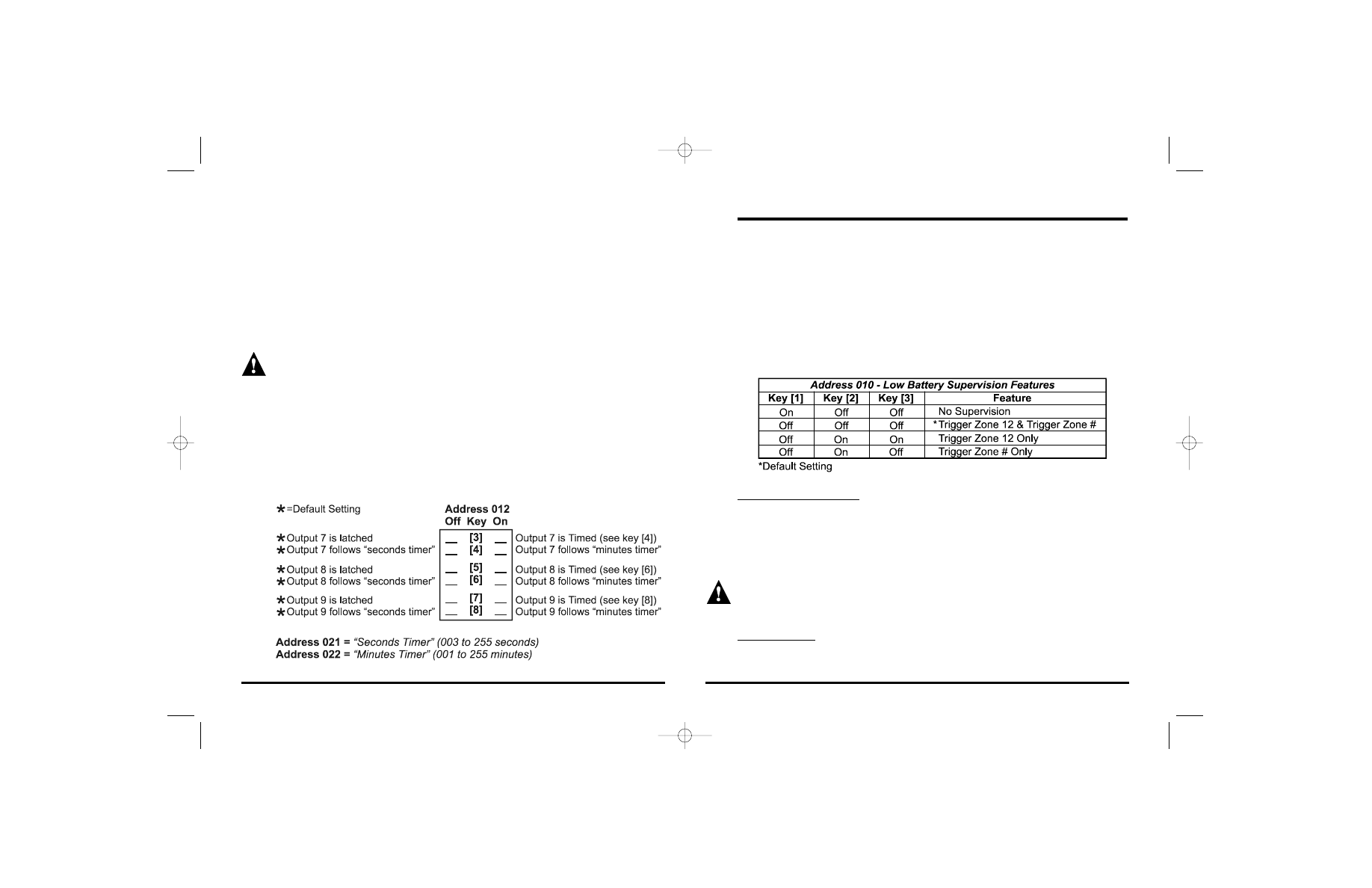
5.4 Program Outputs 7 to 9
Address 012; Keys [3] to [8] and Address 021 & 022
When one or more remote controls have been assigned to the receiver, it reserves
outputs 7 to 9. These outputs are activated by pressing a specific button on any assigned
remote control as explained in section 2.5 on page 8. Program the output to either latch
until the button is pressed again or to latch until the selected timer has run-out as indicated
by the table below.
18
19
Libeei04.qxd 4/11/2002 9:36 AM Page 18
Trigger Zone #:
If a transmitter has not sent any type of signal for the period defined by the check-
in timer (see below), the receiver will trigger the zone output from which the signal
was supposed to originate.
When using this option, you will not be able to differentiate between an open
zone and a check-in failure as they will both trigger the zone output.
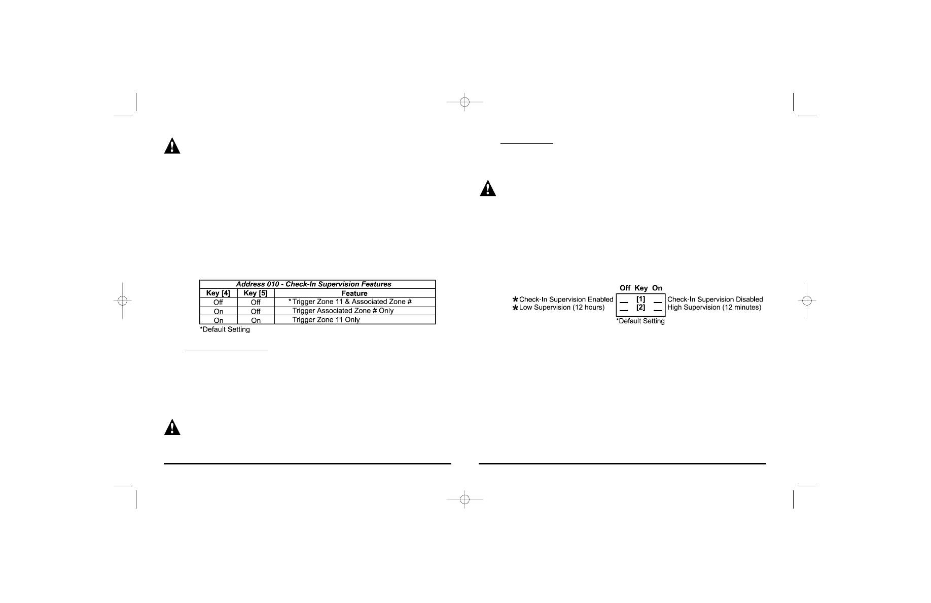
6.2.1 Check-In Timer
Address 012; Keys [1] & [2]
This timer represents the amount of time the receiver will wait for any kind of
signal from a transmitter before generating a check-in failure. Please note that
the receiver’s Check-In Timer must be set to the same setting as all transmitter
supervision settings. For example, if all the transmitters are set for high
supervision the control panel must also be set for high supervision. The timer will
reset for each transmitter whenever a signal is received from the transmitter.
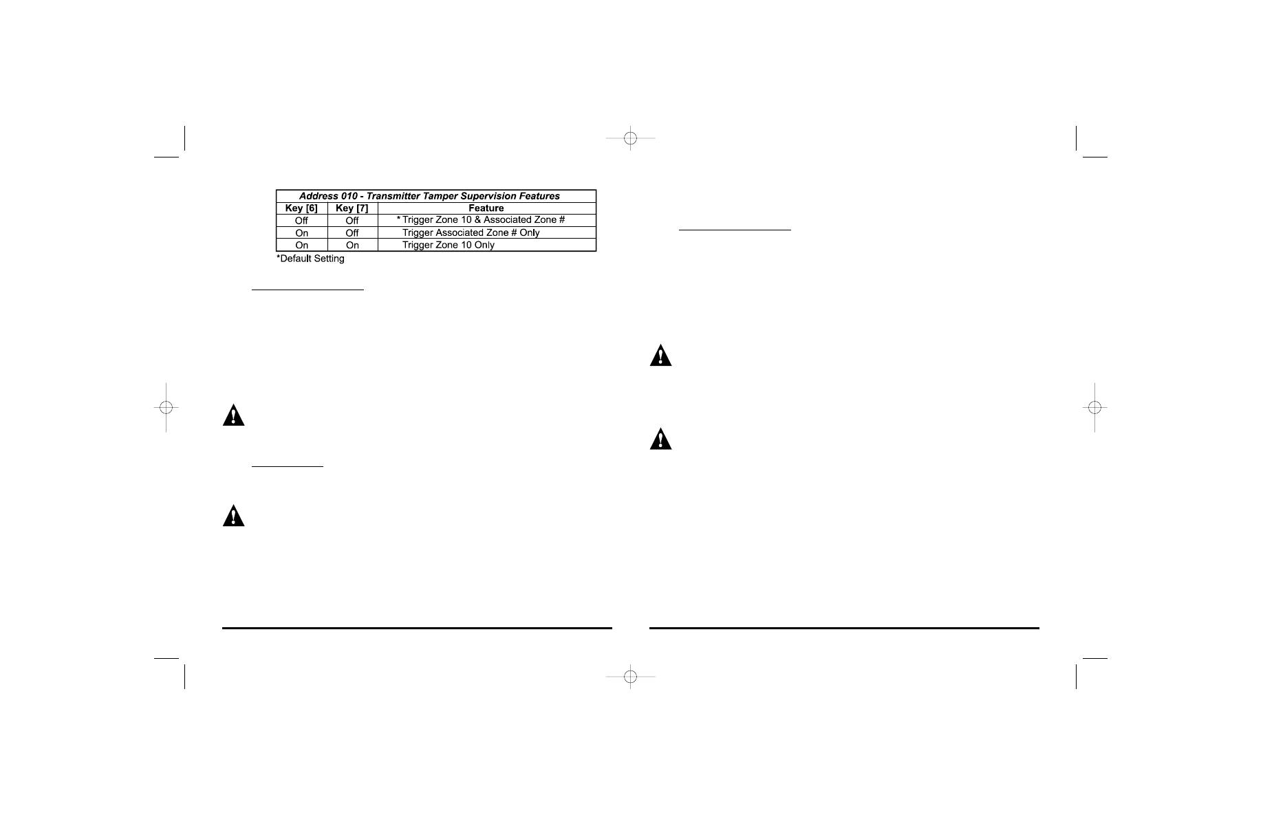
6.3 Transmitter Tamper Supervision
Address 010; Keys [6] & [7]
Whenever a tamper switch, on a transmitter is opened (cover removed), the
transmitter will send a tamper signal. When the signal is received, the receiver will
display that trouble condition on the receiver’s service keypad as described in the
Trouble Display Mode section 6.5. The receiver can also be programmed to
respond to a tamper failure by triggering zone 10 and/or by triggering the specific
zone output from which the signal originated. Please refer to the table below to set
the desired options.
21
When using this option, you will not be able to differentiate between an open
zone and a low battery as they will both trigger the zone output.
6.2 Check-In Supervision
Address 010; Keys [4] & [5]
The receiver waits for each transmitter in the wireless system to send a transmitter
status signal within a specified period in order to confirm their presence and
functionality. If a signal is not received from any transmitter within the period
specified by the Check-In Timer (see section 6.2.1), a trouble condition will be
displayed on the receiver's service keypad as described in section 6.5, Trouble
Display Mode. The receiver can also be programmed to respond to a check-in
failure by triggering zone 11 and/or by triggering the specific zone output from which
the signal was supposed to originate. Please refer to the table below to set the
desired options.
Trigger Zone Output 11:
If set to trigger zone output 11, the receiver reserves zone 11 to trigger every time
a check-in failure is detected from any of the transmitters. If zone output 11 is
connected to a zone input on the control panel, the control panel will then generate
an alarm every time there is a check-in failure in the system. Alternatively, the output
can be connected to another device such as an LED or relay.
You will not be able to assign a transmitter to zone output 11 if it is reserved
for check-in supervision. If check-in supervision is enabled and set to trigger
zone output 11 after a transmitter has already been assigned to zone output
11, the receiver will erase the zone assignment and enable check-in
supervision.
20
Libeei04.qxd 4/11/2002 9:36 AM Page 20
this feature turn the [8] key off in address 010, turn the [8] key on to disable
Receiver Tamper Supervision.
Trigger Zone Output 10:
If set to trigger zone 10, the receiver reserves zone 10 to trigger every time there is
a tamper on the receiver. Note if used in conjunction with the transmitter tamper
supervision (see section 6.3), zone 10 will trigger every time a tamper is received
from either a transmitter or the receiver. If zone output 10 is connected to a zone
input on the control panel, the control panel will then generate an alarm every time
there is a tamper failure in the system. Alternatively, the output can be connected to
another device such as an LED or relay.
You will not be able to assign a transmitter to zone output 10 if it is reserved
for receiver tamper supervision. If receiver tamper supervision is enabled and
set to trigger zone output 10 after a transmitter has already been assigned to
zone output 10, the receiver will erase the zone assignment and enable
receiver tamper supervision.
VERY IMPORTANT!
If the receiver tamper supervision is enabled when installing the security
system, please make sure the cover of the receiver is affixed or place a piece
of tape over the tamper switch to hold it down. Otherwise, when verifying the
functionality of the transmitters, the receiver will trigger zone output 10,
which will appear as though the transmitter is not functioning.
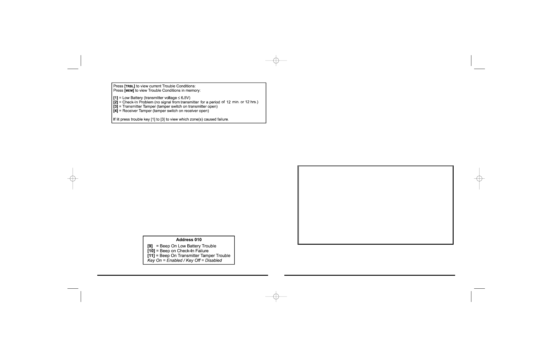
6.5 Trouble Display Mode
Four trouble conditions are continuously monitored by the receiver, the status of
which is displayed on the receiver's service keypad. When one of these trouble
conditions occurs, the receiver will illuminate the [
TRBL
] key on the keypad. Press
the [
TRBL
] key (key will flash) to view the current trouble condition(s) as described
in the table below. To view the zones causing the trouble failure, press the desired
trouble key [1] to [3] after which keys [1] through [12] represent zones 1 through 12.
Any lit keys represent zones causing the trouble failure. The trouble display mode
does not function with remote controls.
23
Trigger Zone Output 10:
If set to trigger zone 10, the receiver reserves zone 10 to trigger every time a tamper
signal is received from any of the transmitters. Note if used in conjunction with the
receiver tamper supervision (see section 6.4), zone 10 will trigger every time a
tamper is received from either a transmitter or the receiver. If zone output 10 is
connected to a zone input on the control panel, the control panel will then generate
an alarm every time there is a tamper failure in the system. Alternatively, the output
can be connected to another device such as an LED or relay.
You will not be able to assign a transmitter to zone output 10 if it is reserved
for transmitter tamper supervision. If transmitter tamper supervision is
enabled and set to trigger zone output 10 after a transmitter has already been
assigned to zone 10, the receiver will erase the zone assignment and enable
transmitter tamper supervision.
Trigger Zone #:
When a transmitter sends a tamper signal, the receiver will trigger the zone output
from which the signal originated.
When using Zone # only option, you will not be able to differentiate between
an open zone and a tamper as they will both trigger the zone output.
6.4 Receiver Tamper Supervision
Address 010; Key [8]
Whenever the tamper switch on the receiver is opened (cover removed), the
receiver will display that trouble condition on the receiver’s service keypad as
described in the Trouble Display Mode section 6.5. The receiver can also be
programmed to respond to a tamper failure by triggering zone output 10. To enable
22
Libeei04.qxd 4/11/2002 9:36 AM Page 22
6.8 Signal Strength Indicator Mode
In order to verify if the signal from the transmitter to the receiver is strong enough
to function properly, the receiver can display the relative signal strength on the
receiver's keypad. To enter the signal strength indicator mode press the [2
ND
] key
followed by the zone number (keys [1] to [12]) you wish to view. Illuminated keys
represent zones that have been assigned a transmitter. After entering the desired
zone, the illumination of keys [1] to [12] represent a relative display of the signal
strength. If all twelve keys are lit, the reception of the selected zone is more than
adequate. If only the [1] key is lit, the reception of the selected zone is weak. If no
keys are lit, the selected zone has a check-in problem or the zone has not been
assigned a transmitter. If the transmission is too weak, re-locating the transmitter by
a few inches can greatly improve the reception. The signal strength indicator mode
does not function with remote controls.
WARRANTY
The Seller warrants its products to be free from defects in materials and
workmanship under normal use for a period of one year. Except as specifically
stated herein, all express or implied warranties whatsoever, statutory or otherwise,
including without limitation, any implied warranty of merchantability and fitness for a
particular purpose, are expressly excluded. Because Seller does not install or
connect the products and because the products may be used in conjunction with
products not manufactured by Seller. Seller cannot guarantee the performance of
the security system. Seller obligation and liability under this warranty is expressly
limited to repairing or replacing, at Seller's option, any product not meeting the
specifications. In no event shall the Seller be liable to the buyer or any other person
for any loss or damages whether direct or indirect or consequential or incidental,
including without limitation, any damages for lost profits stolen goods, or claims by
any other party, caused by defective goods or otherwise arising from the improper,
incorrect or otherwise faulty installation or use of the merchandise sold.
25
6.6 Trouble Memory
The “Liberator” keeps the trouble conditions listed in section 6.5 in memory. The
[
MEM
] key will illuminate whenever there is a trouble condition in memory. To view
the trouble condition(s) in memory, press the [
MEM
] key ([
MEM
] and [
TRBL
] keys will
flash). Any lit keys represent trouble conditions that have occurred as described in
the table in section 6.5. Press any lit key ([1] to [3]) to view which zones caused the
trouble failure. After which keys [1] through [12] represent zones 1 through 12.
Press the [
CLEAR
] key to exit and erase the memory of the trouble condition being
viewed. Press the [
ENTER
] key to exit without erasing the trouble memory.
6.7 Beep On Trouble
If this feature is enabled, the keypad will emit an intermittent beep tone whenever a
trouble condition occurs in the system. The intermittent beeps will only stop by
pressing the [
TRBL
] or [
MEM
] key followed by pressing the [
CLEAR
] or [
ENTER
] key.
The intermittent beeps will be re-initialized whenever the trouble condition ends and
re-occurs. The beep on trouble can be independently programmed for each trouble
condition as shown in the table below.
24
Libeei04.qxd 4/11/2002 9:36 AM Page 24
Libeei04.qxd 4/11/2002 9:36 AM Page 26
Wyszukiwarka
Podobne podstrony:
Liberator LIB 319 arkusz programowania
Liberalizm-dzieje, Encyklopedia Białych Plam
Holderlin wiersze tłum Libera i wstęp
LIBERALIZM SOCJALNY
Burzyciele i rzeźnicy Od II wojny światowej przez siły masońskie i liberalne
PMCO Liberacki papierowa(1)
6 Liberalizacja rynku gazu i en Nieznany (2)
4s lIBERALIZM
Relacje pomiedzy panstwem a jednostka w mysli liberalnej
MPLP 318;319 17.07.;29.07.2011
Autokracja i liberalna demokracja, socjologia - free
Kom Luks C 319.06[1], PODYPLOMOWE z europejskiego
319
liberalizminterwencjonizmfolie, licencjat, rok 2 semestr 1, polityka gospodarcza, zagadnienia
Istota-liberalizmu, Encyklopedia Białych Plam
więcej podobnych podstron