W9 1549893 01 11
1
ZELIO – control
RM4Uiiii – RM4Jiiii
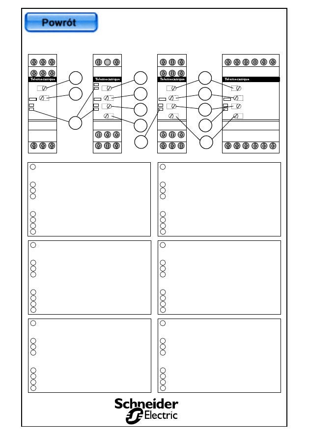
Potentiom¯tre réglage seuil de courant ou
tension gradué en % du maxi de plage
de mesure
Réglage de l'hystérésis
Réglage de la temporisation
Commutateur combinant la sélection de la plage
de temporisation et le type de contrôle
("sous" ou "sur")
Potentiom¯tre réglage de surtension
Potentiom¯tre réglage de sous tension
Sélection des fonctions
Visualisation par LED's
1
2
3
4
5
6
7
8
Current or voltage threshold adjustment
potentiometer graduated in % of maximum
measurement range
Hysterisis adjustment
Time delay adjustment
Switch combining selection of time delay range
and type of control
("under" or "over")
Potentiometer for overvoltage adjustment
Potentiometer for undervoltage adjustment
Function selection
Display by LEDs
1
2
3
4
5
6
7
8
Potentiometer zum Einstellen des Grenzwerts
für Strom oder Spannung in % vom jeweiligen
Höchstwert
Einstellen der Hysterese
Einstellen der Verzögerung
Kombischalter zum Einstellen des
Verzögerungsbereichs und der Prüfart
("unter" oder "auf")
Potentiometer zur Regelung der Überspannung
Potentiometer zur Regelung der Ünterspannung
Funktionswahl
LED-Anzeige
1
2
3
4
5
6
7
8
Potenziometro regolazione soglia di corrente o
tensione graduato in % del valore massimo della
gamma di misura
Regolazione dell'isteresi
Regolazione della temporizzazione
Commutatore che combina la selezione della
gamma di temporizzazione ed il tipo di controllo
("sotto" o "sovra")
Potenziometro regolaezione disovnatensione
Potenziometro regolaezione disottotensione
Selezione delle funzioni
Visualizzazione tramite LED
1
2
3
4
5
6
7
8
Potenciómetro de ajuste del umbral de corriente
o tensión graduado en % del máximo de margen
de medición
Ajuste de la histéresis
Ajuste de la temporización
Conmutador que combina la selección del
margen de temporización y el tipo de control
("sub" o "sobre")
Potenciómetro ajuste de sobre tensión
Potenciómetro ajuste de sub tensión
Selección de las funciones
Visualización por LED
1
2
3
4
5
6
7
8
Potencjometr nastawy poziomu pràdu
lub napi´cia wyskalowany
w % maksimum zakresu pomiarowego
Nastawa histerezy
Nastawa zw∏oki czasowej
Prze∏àcznik ∏àczàcy wybór zakresu zw∏oki
czasowej i typu pomiaru/kontroli
("under" = "pod" lub "over" = "nad")
Potencjometr nastawy górnego poziomu napi´cia
Potencjometr nastawy dolnego poziomu napi´cia
Wybór funkcji
Sygnalizacyjna dioda (diody) LED
1
2
3
4
5
6
7
8
A
T
TR 03/2000
RM4UA0ii
RM4JA0ii
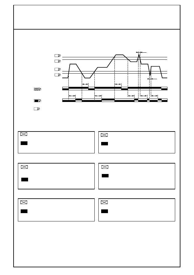
U
RM4UA
U-%
R
A1
A2
C
B1
B2
B3
B1
B2
B3
18
16
15
HYS
RM4UB
U
RM4UB
>U
>U
R
L1
L3
18
15
16
28
25
26
<U
<U
FUNCTION
DELAY-t
RM4UA3ii
RM4JA31i
U
RM4JA
I-%
R
A1
C
A2
18
16
15
28
26
25
HYS
Function/Delay
B1
B2
B3
RM4JA32i
U
RM4JA
I-%
R
A1
C
A2
18
16
15
28
26
25
HYS
Function/Delay
1
2
3
4
5
6
1
2
8
8
8
7
3
2
ZELIO – control
RM4Uiiii – RM4Jiiii
Diody LED na RM4
U
L1L3
16
18
15
26
28
25
16
18
15
26
28
25
R
> U
>
< U
UA
UB
JA
UB
>U
A1
L1
A2
L3
A1
L1
A2
L3
L1L3
<
<U
OK
OK
UA3
JA3
< 0
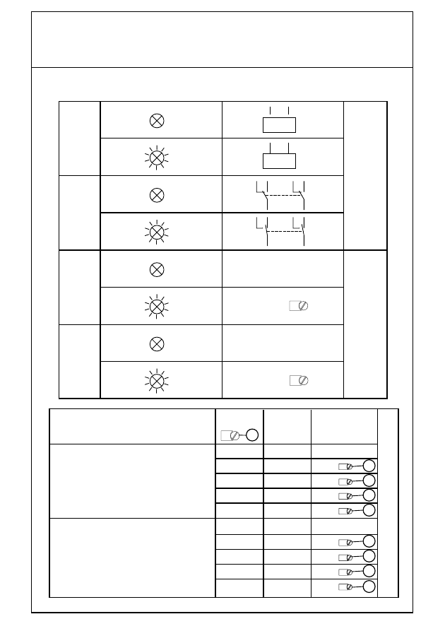
< 1
< 3
< 10
< 30
>0
> 1
> 3
> 10
> 30
Function /
delay
Fonction / Function / Funktion /
Funzione / Función /
Funkcja
t
t
0
0
0,05 … 1 s
0,15 … 3 s
0,5 … 10 s
1,5 … 30 s
0
0,05 … 1 s
0,15 … 3 s
0,5 … 10 s
1,5 … 30 s
Contrôle de sous- tension / courant
Undervoltage or undercurrent control
Prüfen von Unterspannung oder Unterstrom
Controllo di sotto-tensione o sotto-corrente
Control de la subtensión o de la subcorriente
Kontrola podnapi´ciowa lub podpràdowa
Contrôle de surtension / courant
Overvoltage or overcurrent control
Prüfen von Überspannung oder Überstrom
Controllo di sovratensione o sovra-corrente
Control de la subtensión o de la subcorriente
Kontrola nadnapi´ciowa lub nadpràdowa
1 s x
3 s x
10 s x
30 s x
0
1 s x
3 s x
10 s x
30 s x
4
3
%
3
%
3
%
3
%
3
%
3
%
3
%
3
%
3
ZELIO – control
RM4Uiiii – RM4Jiiii
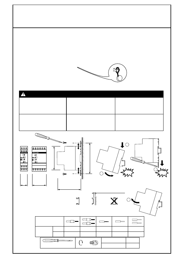
Ø 3,5
mm
2
AWG
RM4Uiii
RM4Jiii
0.14…1.5
26…16
0.14…1.5
26…16
0.14…2.5
26…14
0.14…4
26…12
0.14…2.5
26…14
0.6
5.4
Nm
funt-cal
C
22.5
45
DANGER / DANGER / WARNUNG / PELIGRO / PERICOLO /
UWAGA
HAZARDOUS VOLTAGE
Disconnect all power before
servicing equipement.
Electric shock will result in
death or serious injury
TENSION DANGEREUSE
Coupez l'alimentation avant de
travailler sur cet appareil.
Une électrocution entrainera la
mort ou des blessures graves.
GEFAHRLICHE SPANNUNG
Vor dem Arbeiten an dem Gerät
dessen Stromversorgung abschalten
Elektrischer Schlag mit Lebensgefahr
bzw. schweren Verletzungen
TENSION PERICOLOSA
Scollegare l'apparecchio dalla presa
di corrente prima di qualsiasi intervento
Una scarica elettrica potrebbe
causare la morte o gravi lesioni.
TENSIÓN PELIGROSA
Desconecte toda alimentación
antes de realizar el servicio.
Una descarga eléctrica podriá
provocar la muerte o lesiones serias.
NIEBEZPIECZNE NAPI¢CIE
Roz∏àczyç wszystkie obwody zasilajàce
przed serwisowaniem.
Pora˝enie pràdem mo˝e spowodowaç
Êmierç lub powa˝ne obra˝enia.
> 7,5 mm (0.30 in.)
1
2
Ø 4
Ø 4
Klik !
1
2
Klik !
80
78
90
B1
B2
B3
U
RM4JA
I-%
R
A1
C
A2
18
16
15
28
26
25
HYS
FUNCTION
Function/Delay
B1
B2
B3
U
RM4JA
I-%
R
A1
C
A2
18
16
15
28
26
25
HYS
Function/Delay
4
ZELIO – control
RM4Uiiii – RM4Jiiii
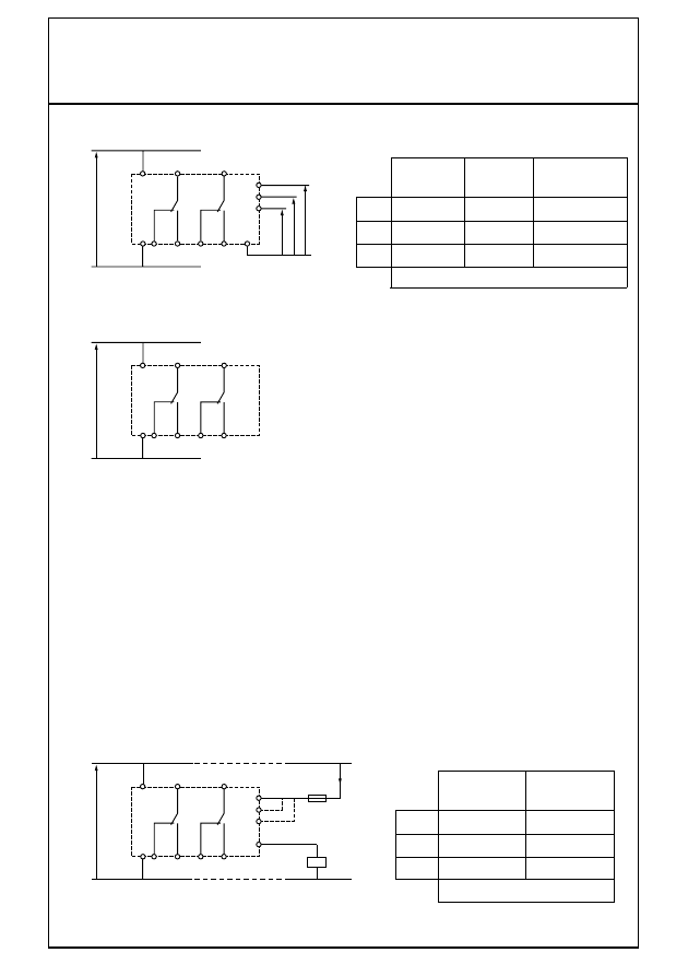
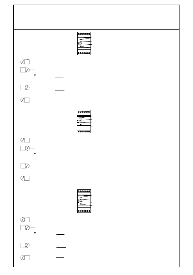
B3
B2
B1
C
A2
A1
B3-C
B2-C
B1-C
0,5…5 V
0,3…3 V
0,05…0,5 V
10…100 V
5…50 V
1…10 V
50…500 V
30…300 V
UA01
UA31
UA02
UA32
UA03
UA33
16
18
U
c
26
28
RM4UA
RM4UB
L3
L1
16
18
U
c
= U
m
U
m
U
m
U
m
26
28
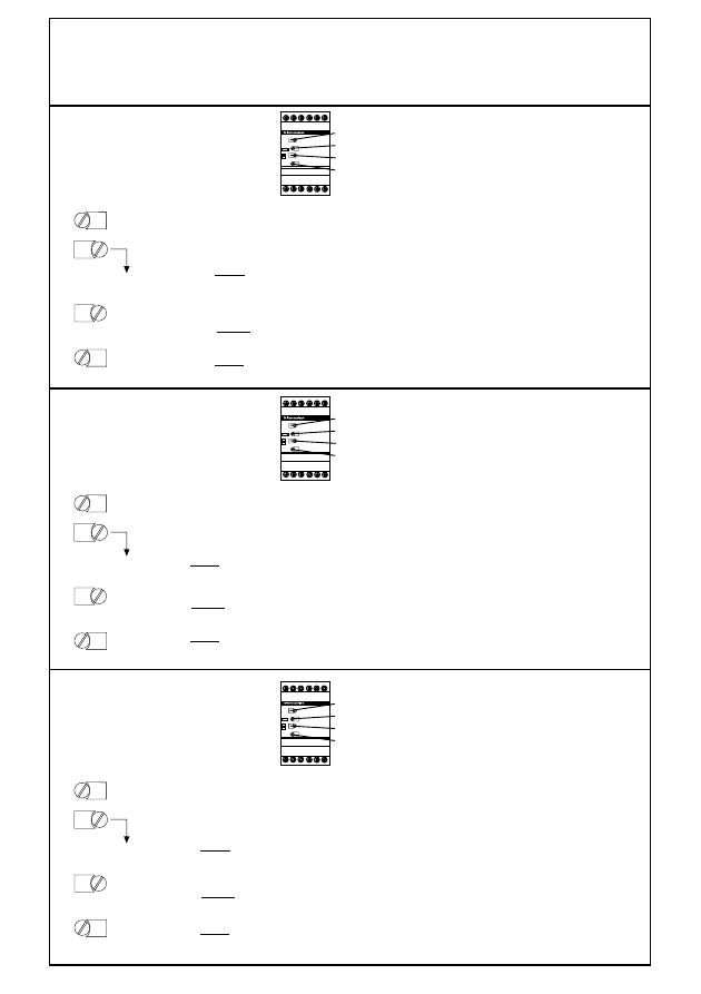
B3
B2
B1
C
A2
A1
16
18
U
c
26
28
I
m
B3-C
B2-C
B1-C
0,1…1 A
10…100 mA
3…30 mA
3…15 mA
1…5 A
0,3…1,5 A
JA01
JA31
JA32
15
25
15
25
15
25
U m
I m
RM4 JA
U
c
= Tension d'alimentation
U
m
= Tension ∫ mesurer
I
m
= Courant ∫ mesurer
U
c
= Supply voltage
U
m
= Voltage to be measured
I
m
= Current to be measured
U
c
= Versorgungsspannung
U
m
=
ausmessen spannung
I
m
=
ausmessen stromstärke
U
c
= Tensione di alimentazione
U
m
=
Tensione da misurare
I
m
= C
orrente da misurare
U
c
= Tensión de alimentación
U
m
= T
ensión a medir
I
m
= C
orriente a medir
U
c
=
Napi´cie zasilajàce
U
m
= Napi´cie mierzone
I
m
= Pràd mierzony
5
ZELIO – control
RM4Uiiii – RM4Jiiii
t
t
< t
0 V
t
t
t
t
t
< t
15/18 25/28
15/16 25/26
15/18 25/28
15/16 25/26
U
L1 L3
> U
> U
0,95 x
1,05 x
Function
Function
< U
< U
RM4UBii
Diagramme fonctionnel / Operating diagram / Funktionsdiagramm /
Diagramma funzionale / Diagrama funcional /
Schemat funkcjonalny
t =
s
DELAY
Diese Funktion verhindert, daß kurzfristige
Spannungsänderungen die Auslösung
des Relais verursachen.
Diese Funktion ermöglicht die Erfassung
aller Fehler und verzögert das Wiedereinschalten
des Relais.
Questa funzione permette di non prendere in
considerazione le sovra-o sottotensioni transitorie.
Questa funzione permette di prendere in
considerazione tutti i superamenti e ritarda
il reinserimento dei rel¯.
Esta función permite no tomar en cuenta
las "sobre" o "sub" tensiones transitorias.
Esta función permite tomar en cuenta
todos los sobrepasamientos y retrasa la
reconexión del relé.
Ta funkcja mo˝e byç u˝yta do opóênienia
reakcji na chwilowe wzrosty lub spadki napi´cia.
Ta funkcja mo˝e byç u˝yta do reakcji
na wszystkie przekroczenia nastawionych wartoÊci;
opóênia ona powtórne zamkni´cie styków.
Cette fonction permet de ne pas prendre
en compte les "sur" ou "sous" tensions transitoires.
Cette fonction permet de prendre en
compte tous les dépassements et retarde
le réenclenchement du relais.
This function can be used to suppress
the response to transient over- or undervoltage.
This function can be used to respond to
all overshoots; it delays the reclosing of the relay.
6
ZELIO – control
RM4Uiiii – RM4Jiiii
< t
t
15/18
15/16
S2
S1
S2 = S1-(S1 x %)
25/28
25/26
U
m
/ I
m
U
c=A1-A2
R
I-%/U-%
RM4UAii/RM4JAii
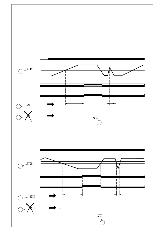
Contrôle de surtension (RM4UA) ou sur-courant (RM4JA) /
Overvoltage (RM4UA) or overcurrent control (RM4JA) /
Prüfen von Überspannung (RM4UA) oder Überstrom (RM4JA) /
Controllo di sovratensione (RM4UA) o sovra-corrente (RM4JA) /
Control de sobretensión (RM4UA) o sobrecorriente (RM4JA) /
Kontrola nadnapi´ciowa (RM4UA) lub nadpràdowa (RM4JA)
Contrôle de sous-tension (RM4UA) ou sous-courant (RM4JA) /
Undervoltage (RM4UA) or undercurrent control (RM4JA) /
Prüfen von Unterspannung (RM4UA) oder Unterstrom (RM4JA) /
Controllo di sotto-tensione (RM4UA) o sotto-corrente (RM4JA) /
Control de subetensión (RM4UA) o subcorriente (RM4JA) /
Kontrola podnapi´ciowa (RM4UA) lub podpràdowa (RM4JA)
2
2
1
1
4
< t
t
15/18
15/16
S1
S2
S2 = S1+(S1 x %)
25/28
25/26
U
m
/I
m
U
c = A1-A2
R
I-%/U-%
HYS
HYS
Function/DELAY
4
Function/DELAY
t ~ 80ms
4
Function/DELAY
4
Function/DELAY
t ~ 80ms
7
ZELIO – control
RM4Uiiii – RM4Jiiii
Exemple de réglage
Réglages :
• Réglage de fonction et de la gamme de temporisation commutateur 4 :
– déterminer le type de contrôle surintensité ou sous-intensité, ici surintensité,
– déterminer la gamme de temporisation, immédiatement supérieure au temps désiré, dans l'exemple ci-dessus 10 s.
• Réglage fin du temps de temporisation :
En fonction du maxi de plage affiché en 4 (dans l'exemple ci-dessus : 10 s) afficher ∫ l'aide du potentiom¯tre 3 la valeur
du temps voulue en % de la valeur 4. Dans l'exemple ci-dessus le temps recherché = 5 s donc :
Réglage 3 =
5 x 100
= 50 %
10
• Régler le potentiom¯tre de réglage du seuil de courant rep¯re 1 en pourcentage du maxi de la plage de mesure choisie
lors du câblage. Dans l'exemple ci-dessus : câblage B3-C, maxi de la plage de mesure 15 A, donc :
Réglage 1 =
13 x 100
= 87 %
15
• Régler l'hystérésis rep¯re 2 en % de la valeur de seuil, dans notre exemple :
Réglage 2 =
13 - 11
= 15,4 %
13
• M˘me principe pour réglage des RM4UAii
Seuil de surintensité ∫ : 13 A.
Temporisation du relais de sortie : 5 s.
Seuil de courant de réarmement : 11 A.
Tension d'alimentation : 127 V a
Produit choisi RM4-JA32MW
Raccordement du courant ∫ mesurer B3-C (3 ∫ 15 A)
B1
B2B3
U
RM4JA
I-%
R
A1
C
A2
18
16
15
2
8
2
6
2
5
HYS
Function/Delay
1
2
3
4
I-%
HYS
Function/Delay
>10
-50
-90
15
Example of adjustment
Adjustments :
• Adjustment of switch 4 function and time delay range :
– determine the type of control, overcurrent or undercurrent, in this case overcurrent,
– determine the time delay range immediately above the desired time, in the example above 10 sec.
• Fine adjustment of time delay :
As a function of the maximum of the range displayed by 4 (in the example above: 10 sec.) display by means of potentio-
meter 3 the value of the time desired as a % of the value 4. In the example above, the time desired = 5 sec., therefore :
Adjustment 3
=
5 x 100
= 50 %
10
• Adjust the current threshold potentiometer, mark 1, as a percentage of the maximum of the measurement range selected
at the time of wiring. In the example above: wiring B3-C, maximum of the measurement range, therefore 15 A :
Adjustment 1 =
13 x 100
= 87 %
15
• Adjust the hysteresis, mark 2, as a percentage of the threshold value, in our example:
Adjustment 2 =
13 - 11
= 15,4 %
13
• The same principle as for adjustment of the RM4UAii
Overcurrent threshold : 13 A.
Output relay time delay : 5 s.
Reset current threshold : 11 A.
Power supply voltage : 127 V a
Product selected : RM4-JA32MW
Connection of current to be measured B3-C (3 to 15 A)
B1
B2B3
U
RM4JA
I-%
R
A1
C
A2
18
16
15
2
8
2
6
2
5
HYS
Function/Delay
1
2
3
4
I-%
HYS
Function/Delay
>10
-50
-90
15
Einstellen Beispiel
Einstellen:
• Einstellen der Funktion und des Verzögerungsbereichs von Schalter 4
– Prüfart bestimmen – Überstrom oder Unterstrom, hier: Überstrom
– Verzôgerungsbereich bestimmen, unmittelbar über der gewûnschten Zeit, 10 sec in dem nachfolgenden Beispiel
• Einstellen des Endes der Verzögerungszeit:
Je nach dem bei 4 angezeigten Höchstwert für den Bereich (10 sec in dem nachfolgenden Beispiel), den gewünschten
Wert mit dem Potentiometer 3 in % von Wert 4 einstellen. In dem nachfolgenden Beispiel beträgt die gesuchte Zeit = 5 sec, somit
Einstellen 3
=
5 x 100
= 50 %
10
• Potentiometer zum Einstellen des Grenzwerts für Strom - Markierung 1 – in % vom bei der Verdrahtung gewählten
Höchstwert des Meßbereichs einstellen. In dem nachfolgenden Beispiel! Verdrahtung B3-C, Höchstwert des Meßbereichs, somit
Einstellen 1 =
13 x 100
= 87 %
15
• Hysterese – Markierung 2 – in % vom Grenzwert einstellen, in unserem Beispiel:
Einstellen 2 =
13 - 11
= 15,4 %
13
• Dasselbe Prinzip wie beim Einstellen der RM4UAii
Beispiel für zu messenden Überstrom : 13 A.
Verzögerung des Ausgangsrelais : 5 s.
Grenzwert für den Wiedereinschaltstrom : 11 A.
Versorgungsspannung : 127 V a
GewähltesProdukt: RM4-JA32MW
Anschluß für den zu messenden Strom B3-C (3 - 15 A)
B1
B2B3
U
RM4JA
I-%
R
A1
C
A2
18
16
15
2
8
2
6
2
5
HYS
Function/Delay
1
2
3
4
I-%
HYS
Function/Delay
>10
-50
-90
15
8
ZELIO – control
RM4Uiiii – RM4Jiiii
Esempio di regolazione
Soglia di sovraintensit∫ : 13 A.
Temporizzazione del rel¯ di uscita : 5 s.
Soglia di corrente di riarmo : 11 A.
Tensione di alimentazione : 127 V a
Regolazioni :
• Regolazione di funzione e della gamma di temporizzazione commutatore 4
– determinare il tipo di controllo di sovraintensit∫ o sotto-intensit∫, qui sovraintensit∫,
– determinare la gamma di temporizzazione, immediatamente superiore al tempo desiderato, nell›esempio sopraindicato 10s.
• Regolazione fine del tempo di temporizzazione :
In funzione del valore massimo di gamma visualizzato in 4 (nell›esempio sopraindicato : 10 s), visualizzare mediante
il potenziometro 3 il valore del tempo voluto in % del valore 4. Nell'esempio sopraindicato, il tempo ricercato = 5 s, in conseguenza :
Regolazione 3
=
5 x 100
= 50 %
10
• Regolare il potenziometro di regolazione della soglia di corrente, riferimento 1, in percentuale del valore massimo della
gamma di misura scelta all›atto del cablaggio. Nell'esempio sopraindicato : cablaggio B3-C, valore massimo
della gamma di misura, in conseguenza :
Regolazione 1 =
13 x 100
= 87 %
15
• Regolare l'isteresi, riferimento 2, in percentuale del valore di soglia, nel nostro esempio :
Regolazione 2 =
13 - 11
= 15,4 %
13
• Stesso principio della regolazione dei RM4ii
Prodotto scelto : RM4-JA32MW
Collegamento della corrente da misurare B3-C (3 a 15)
B1
B2B3
U
RM4JA
I-%
R
A1
C
A2
18
16
15
2
8
2
6
2
5
HYS
Function/Delay
1
2
3
4
B1
B2B3
U
RM4JA
I-%
R
A1
C
A2
18
16
15
2
8
2
6
2
5
HYS
Function/Delay
1
2
3
4
B1
B2B3
U
RM4JA
I-%
R
A1
C
A2
18
16
15
2
8
2
6
2
5
HYS
Function/Delay
1
2
3
4
I-%
HYS
Function/Delay
>10
-50
-90
15
Ejemplo del ajuste
Umbral de sobreintensidad : 13 A.
Temporización del relé de salida : 5 s.
Umbral de corriente de rearme: 11 A.
Tensión de alimentación : 127 V a
Ajustes :
• Ajuste de función y de la gama de temporización del conmutador 4
– determinar el tipo de control de sobreintensidad o subintensidad, aquí sobreintensidad
– determinar la gama de temporización, inmediatamente superior al tiempo deseado, en el ejemplo de arriba 10s.
• Ajuste del tiempo de temporización :
En función del máximo de margen visualizado en 4 (en el ejemplo de arriba : 10s) visualizar con la ayuda del
potenciómetro 3 el valor del tiempo deseado en % del valor 4. En el ejemplo de arriba, el tiempo buscado = 5 s, por lo tanto
Ajuste 3
=
5 x 100
= 50 %
10
• Ajustar el potenciómetro de ajuste del umbral de corriente, ítem 1, en porcentaje del máximo del margen de medición
elegido durante el cableado. En el ejemplo de arriba : cableado B3-C, máximo del margen de medición, por lo tanto
Ajuste 1 =
13 x 100
= 87 %
15
• Ajustar la histéresis, ítem 2, en porcentaje del valor de umbral, en nuestro ejemplo :
Ajuste 2 =
13 - 11
= 15,4 %
13
• Mismo principio que para el ajuste de los RM4ii
Producto elegido : RM4-JA32MW
Conexión de la corriente a medir B3-C (3 a 15)
I-%
HYS
Function/Delay
>10
-50
-90
15
Przyk∏ad nastawiania
Poziom nadpràdowy: 13 A.
Zw∏oka zadzia∏ania przekaênika wyjÊciowego: 5 s.
Pràd powrotny: 11 A.
Napi´cie zasilania: 127 V a
Nastawianie:
• Nastawa prze∏àcznika 4 - funkcji i zakresu zw∏oki:
– ustal typ kontroli, nadpràdowej lub podpràdowej, w tym przypadku nadpràdowej,
– ustal zakres zw∏oki, najbli˝szy wi´kszy od czasu ˝àdanego, w tym przyk∏adzie ponad 10 s.
• Precyzyjna nastawa zw∏oki:
Jako funkcj´ maksymalnej wartoÊci zakresu wskazywanej przez 4 (w powy˝szym przyk∏adzie: 10 s), nastaw za pomocà
potencjometru 3 wartoÊç czasu ˝àdanego jako % wartoÊci 4. W powy˝szym przyk∏adzie, czas ˝àdany = 5 s, zatem:
Nastawa 3
=
5 x 100
= 50%
10
• Nastaw potencjometr poziomu pràdu, oznaczony 1, jako procent maksimum wybranego przy okablowywaniu zakresu.
W powy˝szym przyk∏adzie: okablowanie B3-C, zatem maksimum zakresu pomiarowego to 15A:
Nastawa 1 =
13 x 100
= 87%
15
• Nastaw histerez´, oznaczonà 2, jako procent wartoÊci poziomu pràdu, w naszym przyk∏adzie:
Nastawa 2 =
13 - 11
= 15,4%
13
• Te same zasady dotyczà nastawiania RM4ii
Wybrany produkt: RM4-JA32MW
Pod∏àczenie pràdu mierzonego do zacisków B3-C (3 do 15)
I-%
HYS
Function/Delay
>10
-50
-90
15
Document Outline
Wyszukiwarka
Podobne podstrony:
04 1b Zelio Control RM4T instr Nieznany
04 1b Zelio Control RM4L instr uzytk
04 1a ZELIO RELAY PRZEKAZN PANO Nieznany
04 1b Zelio Time RE7 instr uzytkid 4953
04 1b Zelio Time RE7 instr uzytk
04 1b Zelio Time RE8 RE9 instr uzytk
04 1a ZELIO TIME CONTROL PANORA Nieznany (2)
04 1b Phaseo ABL7 RE ABL7 RP in Nieznany (2)
04 18 belki i ramy zadanie 18id Nieznany (2)
02 ZELIO CONTROL CATALOGUE
2014 04 28 23 31 22id 28401 Nieznany
18 04 2013 WBC(LEUKOCYTY)id 176 Nieznany (2)
ac motor control id 50500 Nieznany (2)
więcej podobnych podstron