
Time is running out
Creative Science & Research PO BOX 557 New Albany, IN. 47151 www.fuelless.com
WARNING!
FOR RESEARCH PURPOSES ONLY- BUILD AT YOUR OWN RISK!
1
to
5
0,
00
0V
D
an
ge
r H
ig
h
Vo
lta
ge
Copyright 1996 - 2003 Creative Science & Research
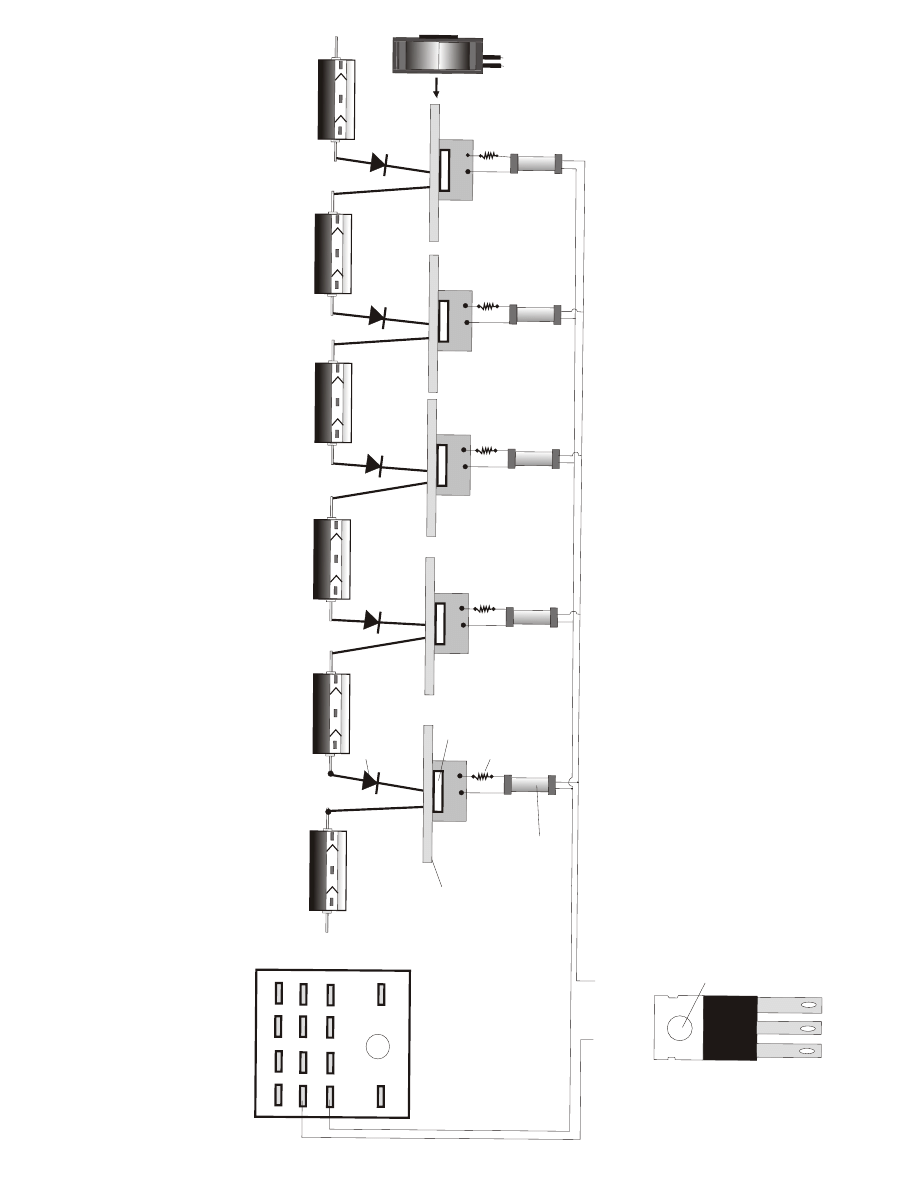
CAPACITOR STEP UP
CAPACITOR STEP UP
CAPACITOR STEP UP
The
Input from 12 vdc batteries or 120 vac
WARNING! We are not responsible for
anything in these plans, you build at
your own risk. Be careful, The high vol-
tages used in these plans can kill you.
# 363-A
This is not a free energy device, but can be used for powering many differant types of free
energy devices. Great for many HV anti-gravity experiments as well, HV with high amps!
Cover Page
CAPACITOR STEP UP
CAPACITOR STEP UP
Transformer
DANGER HIGH VOLT
AGE
carefullyltage can kill you! So please be careful! We are not responsible for anything in
these plans! You build at your own risk. Keep away from children. Use rubber gloves and a
rubber lab coat and shoes. It only takes one mistake with high voltage. Alway's carefully
discharge all capacitors into a HV Coil after usage.

The information we are giving you is confidential and copyrighted information as well as Patent
pending by Creative Science & Research 1996-2004
The plans provided here are to give you a basic idea of what we have developed in high
voltage step up technology. There are many ways to step up voltage, these are just a few
ideas that we have came up with, With these plans it will be easy to step up high Voltage
and keep most of the amperage input. HV with High amps is very much needed in HV research.
To buy such power supplies would cost well over $2000.
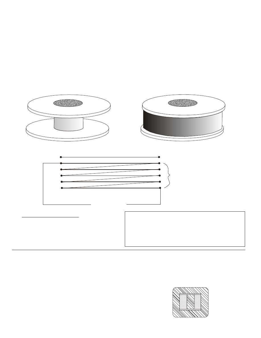
The Air Core and Epoxy Iron core transformer
Make an air core bobbin from PVC plastic sheeting, you can buy 1/8” to 1/4”
plastic sheeting at any sign or screen printing shop or supply company. The
material is great for bobbins and is easy to work with. You can use a matt knife
to cut the material and PVC glue to glue and connect it. You will be making a
round type bobbin, you will need a 2” diameter x 2 inch length of PVC pipe,
Cut a qty of 2, 6” diameter x 1/8” thick pieces of PVC sheeting. Glue one piece
to the bottom of PVC pipe, On the top piece cut a 2” or less hole in the center so
you can get our special soft iron core into the center of the bobbin. After that is
dry you will need to wind 30 strands of #32 copper coated wire side by side
parallel with each other and in equal lengths, you will need 15 small bobbins
with 2 strands per bobbin so you will not need to buy 30 x (6 lbs) spools which
would be very expensive. simply buy 2 large spools of #32 wire and wind them
both at the same time on each 3” spool to get a total of 15 small spools, use a
table top or floor drill press to wind your bobbin coil. This configuration is a
special high capacitance type transformer coil. ( Patent Pending! )
You will now need to make a molded epoxy /soft iron core, ( Patent Pending /(
Creative Science & Research).
You will need High strength 2 ton all purpose epoxy made by Devcon company.
You can buy this at most hardware stores. Now find as many old worn out wall
transformers or HV Microwave transformers as you can find. remove the coil
wire and cut the iron core into small pieces about 1” to 3”. It is best to take apart
each laminate piece of iron first, (if you can get them apart ). You will need an
electric grinder with a fine wheel.
You will be grinding down each small piece, but first you will need to make a
catcher, Find a cardboard box about 10” x 12” line the inside with aluminum foil
2 times, get a small piece of 5” x 6” sheet metal and tape this right under where
the grinding wheel will be throwing the hot sparks from the metal. If you do not
use sheet metal the sparks will burn through the aluminum, Now use duct Tape
to tape the box to the underside of the grinder.( Best to use a grinder that is on a
metal stand.) Now begin grinding down the soft iron and catching it into the box.
Using a pair of pliers to hold each piece. Get as much as you can for now and for
future use.
The Capacitor Step up Transformer #363-A
363_Apg1.cdr
Page 1
Our Iron Core Mold
PVC Bobbin Transformer
The Capacitor Step up Transformer #363-A
363_Apg1.cdr
Page 2
Now take the small soft iron particles and place the iron fillings inside of the
PVC 2” pipe, leave about 1/4” space from the top. Now mix about a 2”
diameter space by 1/4 tall of epoxy, mix it very well. Once you are done,
pour out the iron fillings from the 2” pipe bobbin, onto a plastic or hard card
board piece about 12” x 12” ( to keep epoxy from getting on your table top. )
Steel or plastic surface is best! Now begin adding and mixing the epoxy with
the iron fillings a small amount at a time, you do not want to add to much
epoxy, so it’s going to be a little hard to mix at first, you want the end mix to
be pasty not runny.
Primary # 26 copper wire
Secondary
# 30 copper wire
Example: represents 300 feet of wire(s)
AC Output
AC Input
AC Input
2 strands = 120 vac x 120 vac
3 strands = 120 vac x 240 vac
4 strands = 120vac x 360 vac
or
30 strands = 120 vac x 3,480 vac
199 strands = 120 vac x 23,880 vac output! Wow!
# of strands Input output
You can make Iron core in different strengths by simply adding more iron and making it
pastier or by adding less iron and more epoxy to make it lighter and weaker. Using
less can sometimes be better, because if you mix it right the core becomes very high
efficient meaning the core will be lighter than a solid commercial type core would but
be the same output strength! Why is this? Well, each piece of iron ( If mixed and
prepared correctly ,) becomes a small magnet and there fore they all line up together
like many thousands of small magnets stacked one on top of the other making the
core stronger!
For even higher efficiencies, construct another molded iron core to the outside of the coil, just like
you see in regular transformers. Or you can use an existing transformer iron core from a HV
transformer or a small wall transformer. Simply remove the bottom of core with a hack saw, then
replace your with new multi-strand bobbin, replace the bottom of the core and glue with 50%
epoxy and 50% iron fillings or powder. Clear epoxy the whole thing and let it sit for 24 hrs.
Question: How many turns should I use?
Answer: The less number of winds the more amperage
output, and the loss of heat energy! It is best to wind
about 120 to 200 times. The high capacitance created
in the coil will help generate more amperage at the output.
Cut Away View
The Capacitor Step up Transformer #363-A
Page 3
Now lets take a look at another method we have discovered to be a very
good way to step up voltage and if it is done right you will not lose any
amperage at all but will gain voltage as well as amperage by pulsing very
large HV coils.
For an example: lets use an old Microwave oven transformer, Disconnect the
small secondary wire from the iron core, Do not leave this connected.
For some reason the manufactures connect one lead of the secondary wire to
the iron core??
Now you want to pulse the primary with DC voltages, lets first try a voltage of
90 volts using 10 - 9 volt batteries connected in series. Now connect a 2000
volt diode to the negative wire that you are going to pulse with front E.M.F
and a 2000 volt Capacitor, mylar, aluminum type non-polarized. This set up
will collect the back E.M.F as you pulse the front E.M.F very quickly. Example
simply switch on and off the negative front E.M.F power going into the
secondary coil. ( Not sure which one is the secondary? The secondary will
have the smallest guage wire with the most number of turns than the primary
would be.
Of course you can pulse just 9 volts if you like to test the unit, but higher
voltages work better. Adjust the dc input voltage to the desired amount to get
the output voltage that you want. Use the proper rated capacitor and diode
with the desired output voltage, output volts should be 10 times what the
input voltage will be. The capacitor stack’s the voltage inside of itself, therefor
stepping up the voltage within itself.
( Patent Pending / Copyright 2002 - 2004
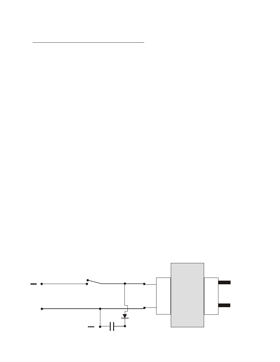
Pulsed HV Back EMF Transf.
Primary
115 vac end
Secondary
DC Pulse
DC Pulse low
Input Voltage
DC Pulse high
Output Voltage
High Voltage
Microwave Transformer
( Amperage Hog! )
+
+
Creative Science & Research PO BOX 557 New Albany, IN. 47151
WARNING!
We are not responsible for anything in these plans! YOU BUILD AT
YOUR OWN RISK! FOR RESEARCH PURPOSES ONLY
HIGH VOLTAGE CAN KILL! USE RUBBER GLOVES WHEN
WORKING WITH ANY HIGH VOLTAGE AND ACID BATTERIES.
Just because it is your project don't assume anything, be safe!
it only takes one mistake and your DEAD!
I’ll say it again!
ONE MISTAKE AND YOUR DEAD! USE RUBBER GLOVES!
USE HIGH VOLTAGE WARNING SIGNS!
Place
these
signs
at
every
entrance
of
your
project
area!
KEEP OUT OF THE REACH OF CHILDREN AND ADULTS.
COVER ALL BATTERY TERMINALS WITH RUBBER OR ANY
OTHER NON CONDUCTIVE MATERIAL. MISTAKES CAN HAPPEN.
PLEASE BE CAREFUL!
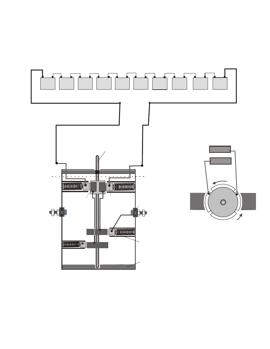
+
12 VDC
DEEP
CYCLE
+
12 VDC
DEEP
CYCLE
+
12 VDC
DEEP
CYCLE
+
12 VDC
DEEP
CYCLE
+
12 VDC
DEEP
CYCLE
+
12 VDC
DEEP
CYCLE
+
12 VDC
DEEP
CYCLE
+
12 VDC
DEEP
CYCLE
+
12 VDC
DEEP
CYCLE
+
12 VDC
DEEP
CYCLE
_
120 V DC
+
_
Please note that 120 volts dc can not be used for house current until it is changed to AC.
but you can run any ac light bulb(s) with it, and some 1500 watt space heaters.
Page 4
The Capacitor Step up Transformer #363-A
What is an inverter?
An inverter steps up a DC incoming voltage from a
12 volt DC battery and converts it to 115 VAC
which can be modified using special techniques to
convert it to house hold sine wave current.
The Hertz output is adjustable, you can easily
adjust it to a common household 60 Hz. Or for
science experiments you can raise the hertz to any
desired amount by simply speeding up the small dc
motor which you will be using along with our
commutator switches that we invented. Most
inverters sold today have an output of 115 volts ac
and the cheap invertors are not sine wave at all. Our
invention uses much less amperage from the battery
than other commercial models. That means your 12
volt battery or battery bank will last longer. Never
let your battery bank go under a 25 discharge,
they will last much longer and save you money!
Copyright 1996 - 2003 Creative Science & Research
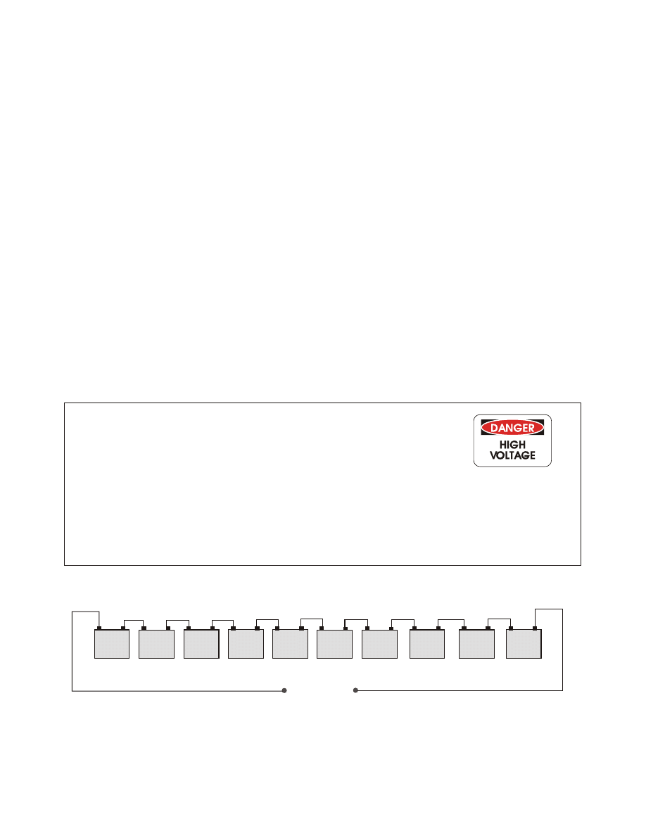
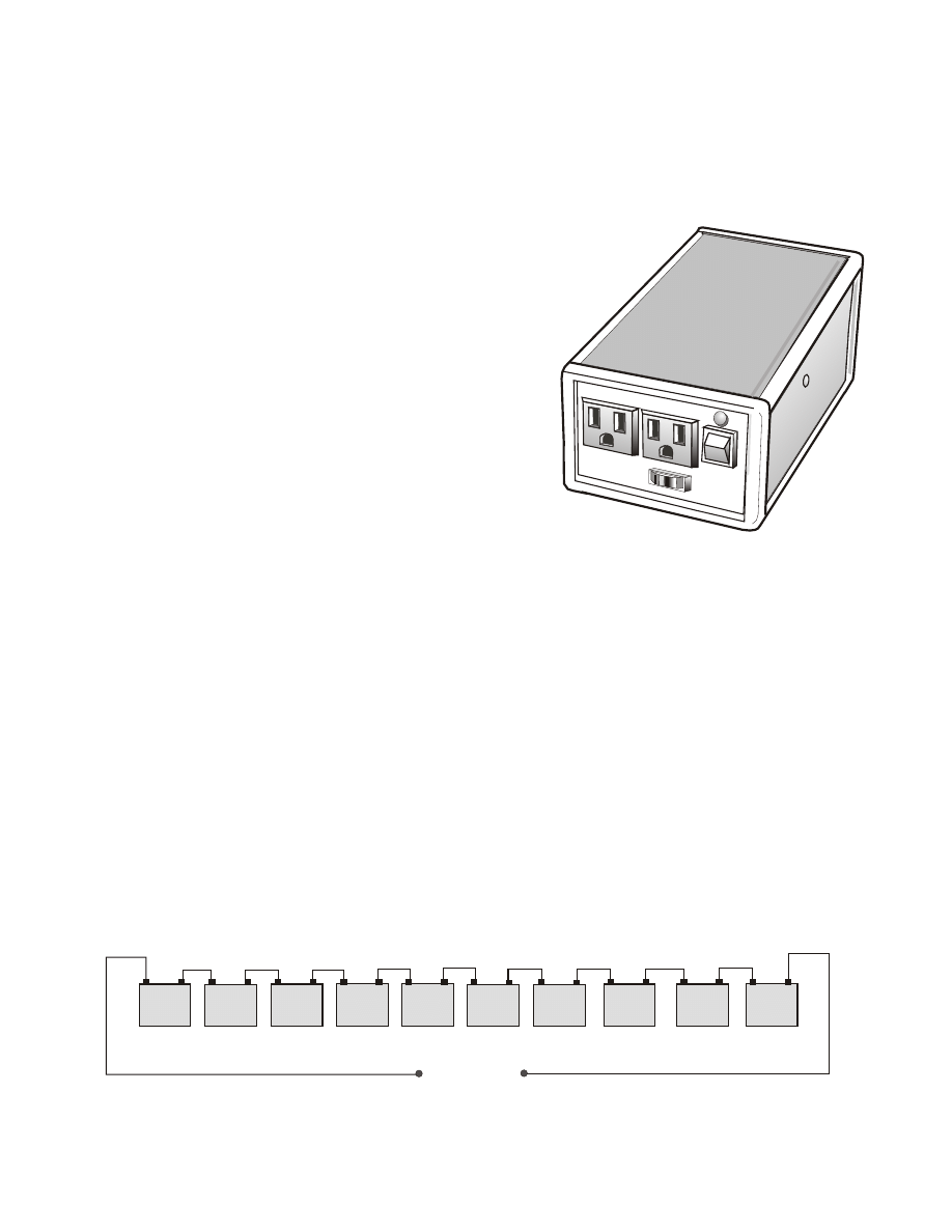
Building a large watt inverter is not extremely simple but if you take your time and do it right you can
save thousands of dollars and you will be learning also. Of course for us it is easy, but once you get the
hang of it you can build more for your own use only! If you wish to manufacture them you must first get
our approval! There is another option to building a 5,000 watt inverter, you can simply connect ten 12
volt deep cycle marine batteries in series as shown below. This can be very dangerous so extreme
caution must be taken! This method eliminates the need to step up the 12 vdc to 120 vdc and you get
much more wattage, 10,000 to 15,000 watts. The 120 vdc is then converted to AC by using our simple
commutator invention, which should be included with these plans. Remember to use the proper wire
rating for DC and AC. The wire for the batteries must be very large gauge to handle the wattage, it is
multi strand wire and together make up about a Vi diameter or more. Make sure your wire is as short as
possible when connecting batteries together. I have never tried it but it seems it would be a very good
idea to use a 10 to 20 amp circuit breaker between your #5 and #6 batteries, this is for safety just in case
you get a short some where. You should be able to find large gauge DC battery wire at a automotive
parts store or Solar Supply house or a local multi store that sells batteries. If you try to use to small of
wire it will limit your wattage output. WARNING! Make sure all connections are very tight and then
paint them with rubber brush-on electrical tape by North American Oil Co. Atlanta GA.
(Hardware stores.) Keep out of reach from anyone!
+
12 VDC
DEEP
CYCLE
+
12 VDC
DEEP
CYCLE
+
12 VDC
DEEP
CYCLE
+
12 VDC
DEEP
CYCLE
+
12 VDC
DEEP
CYCLE
+
12 VDC
DEEP
CYCLE
+
12 VDC
DEEP
CYCLE
+
12 VDC
DEEP
CYCLE
+
12 VDC
DEEP
CYCLE
+
12 VDC
DEEP
CYCLE
_
120 V DC
+
_
Page 5
Please Note that 120 volts dc can not be used for house current until it is changed to AC current!
But you can run as many AC lights bulbs as you want and dc appliances.
The Capacitor Step up Transformer #363-A
Page 6
Copyright 1996 - 2003 Creative Science & Research
OIL
Oil Line
Non-Explosive
type, Such as baby oil?
Leg #1
Leg #2
Negative to Battery
Aluminum bottom plate
Square Steel container
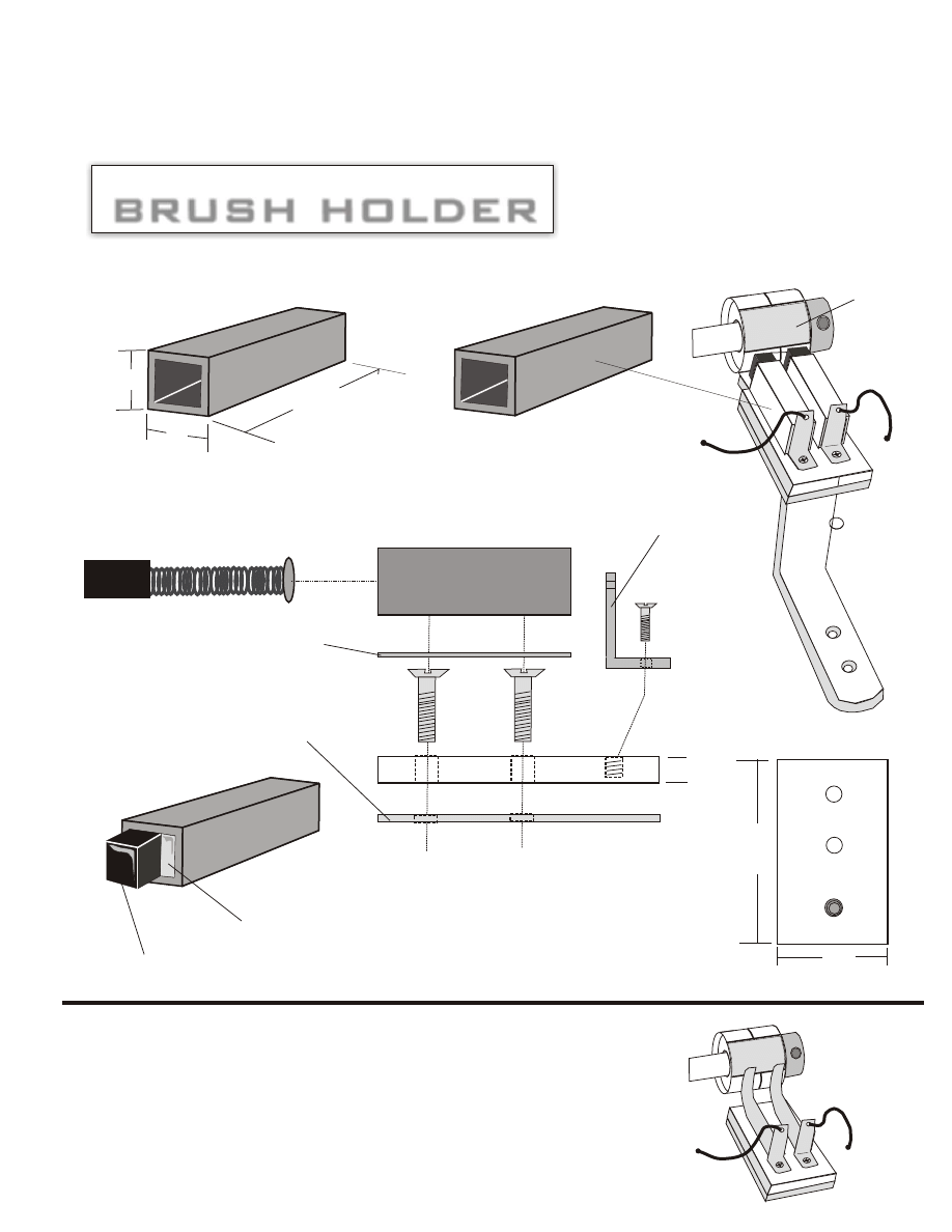
Brushes
Push Springs
Rubber Washers
Turn using Small DC
Free Energy Motor or such..
Top View of
Commutator
Commutator
Conatcts
_
AC Output
120 vdc x 30 amps
AC Output
120 vdc x 30 amps
AC Collector Rings
AC Collector Rings
and brushes
+
_
+
+ - + - +
_
+
12 VDC
DEEP
CYCLE
+
12 VDC
DEEP
CYCLE
+
12 VDC
DEEP
CYCLE
+
12 VDC
DEEP
CYCLE
+
12 VDC
DEEP
CYCLE
+
12 VDC
DEEP
CYCLE
+
12 VDC
DEEP
CYCLE
+
12 VDC
DEEP
CYCLE
+
12 VDC
DEEP
CYCLE
+
12 VDC
DEEP
CYCLE
_
120 V DC
+
_
Converting DC to AC
Optional set up, But, It is much safer to step up a 12 volt or 24 volt battery than to use 10 batteries.
+
Make a safe box to hold batteries, build it out of
½”to 3/4” plywood. Connect all fuses or circuit
breakers outside of box so hydrogen gases will
not explode when charging. Charging produces
explosive gases.
Brushes should be heavy duty, if not, add more wire yourself to the brushes so they will
carry more amperage. More amperage means more wattage output, all wires should be
heavy gauge to match what desired wattage output you want. Container can be any size you
want. Brushes and contacts should be first tested for as long period of time then oil added.
Use a non flammable oil such as baby oil or vegetable oil. If you want 220 volts to run
motors and 220 appliances add another 10 batteries separate banks and converters, that
means you will need two converters and an experience electrical man to help you if you do
not know how to hook up.
The Capacitor Step up Transformer #363-A
Page 7
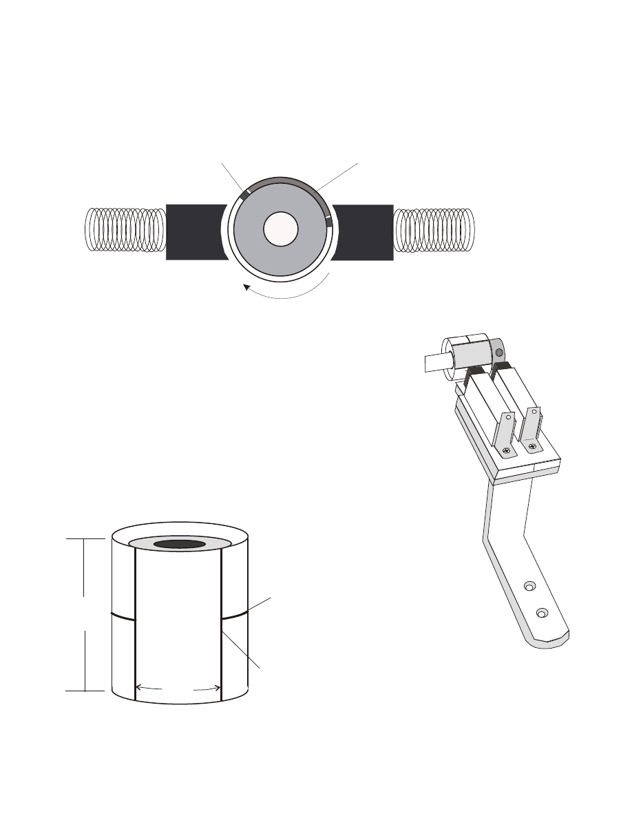
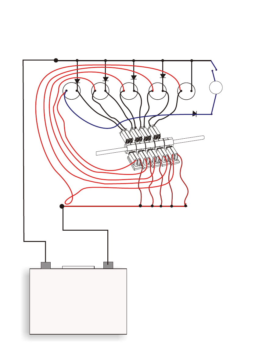
Oil Commutator Switch for Alternating bC to AC
Turn an old 12 vdc 5 amp or 40 amp industrial motor into an Oil Filled Commutator
DC to AC switching apparatus.
The brushes and contacts will be emerged in baby oil or vegetable oil to reduce or
eliminate sparks and heat loss. The motor must be taken apart and the rotor wires that
make up the electromagnetic motor can be taken out, you must then add additional ring
contacts. Or simply use the container and build our copper pipe commutators as seen in
these plans.
As the Commutator turns the incoming 120 volt DC is switched back and forth to the
AC Pickup rings, a second set up AC brushes collects the AC.
Incoming amperage from the batteries must be controlled by using fuses and chokes
and the proper wire size. if you want 30 amp output use a wire that will handle 30 amps.
Now seal all holes and assemble and fill the motor stator container with oil. (It maybe a
good idea to use a non-flammable oil such as baby oil or vegetable oil.) or you can
simply drill small holes in the bottom of the motor and place the entire motor in a solid
can filled with oil. the oil will then fill the motor container and surround the brushes and
contacts
Or you can simply construct your own container housing as so: Container can be clear plexi
glass plastic so you can see what's going on inside, and the top and bottom plates are steel
or aluminum laser cut to your own special size. you can still use a shaft and commutator
contacts from an old DC motor. Be careful 120 vdc has more amperage power than your
house that is why it must be stepped down to safe levels. (The Amperage ) Use house
Circuit Breaker Boxes. And Again Always Use Rubber Gloves. Be safe!
OIL
Oil Line
Non-Explosive
type, Such as baby oil?
Leg #1
Leg #2
Negative to Battery
Aluminum bottom plate
Square Steel container
Brushes
Push Springs
Rubber Washers
Turn using Small DC
Free Energy Motor or such..
Top View of
Commutator
Commutator
Conatcts
_
AC Output
120 vdc x 30 amps
AC Output
120 vdc x 30 amps
AC Collector Rings
AC Collector Rings
and brushes
+
_
+
+ - + - +
+ - + - +
_
+
Copyright 1996 - 2003 Creative Science & Research
The Capacitor Step up Transformer #363-A
+
_
C
a
p
a
c
ito
r
+
_
C
a
p
a
c
ito
r
+
_
C
a
p
a
c
ito
r
+
_
C
a
p
a
c
ito
r
+
_
C
a
p
a
c
ito
r
To Battery Negative
To Battery POSITIVE
Apply a small motor to shaft and turn
Caps connect and then this is timed to
deposit 120 v charge a split second
after connect to the load or a 120vdc
capacitor reservoir.
LOAD
This is our 5,000 watt inverter design, this is a
foundation to work from, of course you can build
it to any wattage you desire. For high wattage
such as 5,000 watts, you must use fat wire and
brushes, ( Large gauge wire ) this design can also
be made non-mechanical by using electronic
switching, but we wanted to make it easy for just
about anyone to build. The commutators are very
easy to build, it may look hard but it is not. We
use our own design using copper piping and J-B
weld epoxy, both are available at any hardware
store near you I am sure.
The commutators are
simply an on and off switch.
when the
commutators hit the front brushes,
the capacitors
are charged with 12 volts dc each,
Then as the
commutators spin toward the back
they shut off
the front 12 vdc charge for the caps
and they then
spin around and hit the back brushes,
which
connect the capacitors in series and step the
Voltage Up tO 120 vdc. The drawings do not show the lull
ten brushes needed, we did not want to make it iook to
complicated. _^/ —
Wires are not shown connected to help show brush assembly.
Sorry the drawing does not show the full ten
brushes to obtain 120 vdc step up
You will need 10 capacitor and diode banks
stacked one on the other. Each capacitor is
rated at 25 volts x 23,500 uf
a 25 v x 4700 uf = about 100 watts output.
INVERTER OPTION #2
Page 8
Copyright 1996 - 2003 Creative Science & Research
The Capacitor Step up Transformer #363-A
J-B Weld Epoxy or
PC 7 Epoxy
Also acts as an insulator!
1/8” plastic square washer
custom made / same size
as aluminum / used as a
insulating washer.
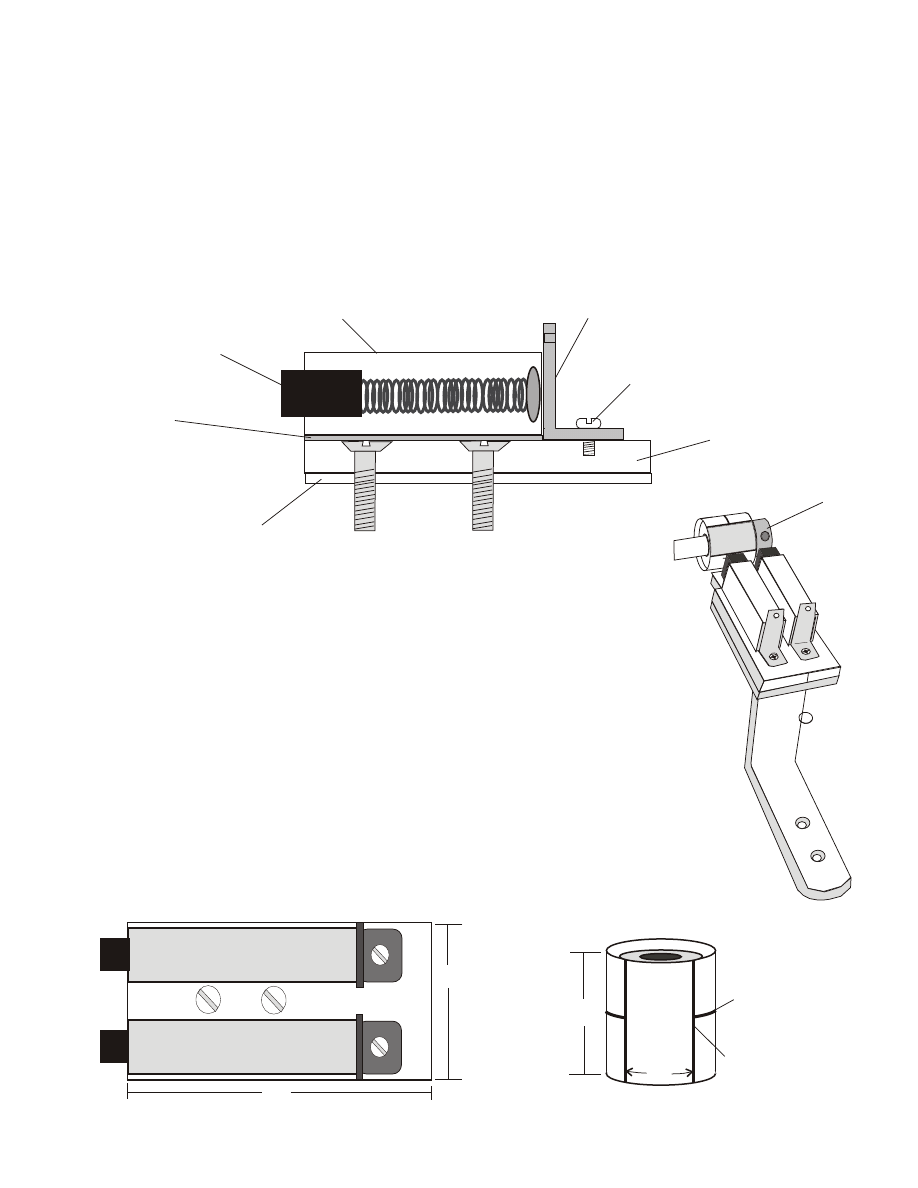
Motor Brush w/spring
5/16” x 1/4”
½”x ½” steel square
3/4” x 1” copper plate
1/4” x 1 1/4” x 2” long
Aluminum
5/16” steel collar,
epoxy to commutator
6-32 x 3/8” steel machine screw
tapped out w/6-3 NC, drill hole 7/64”
SIDE VIEW
#1
#2
The #1 and #2 brushes must not be electrically connected, The
epoxy under each steel brush holder will insulate between the steel
square pieces and the aluminum. Make sure to spread the surface
with an even coat of epoxy. Epoxy glue each steel brush holder
assembly to the aluminum brush holder base, part “G”. Then spray
paint.
The Brush assembly acts as an on and off switch and must be timed
so that the motor runs smoothly and not against it’s self. The
commutator is special made, and as the commutator rotates the
brushes hit the commutator contact bar making a complete Circuit.
Top View
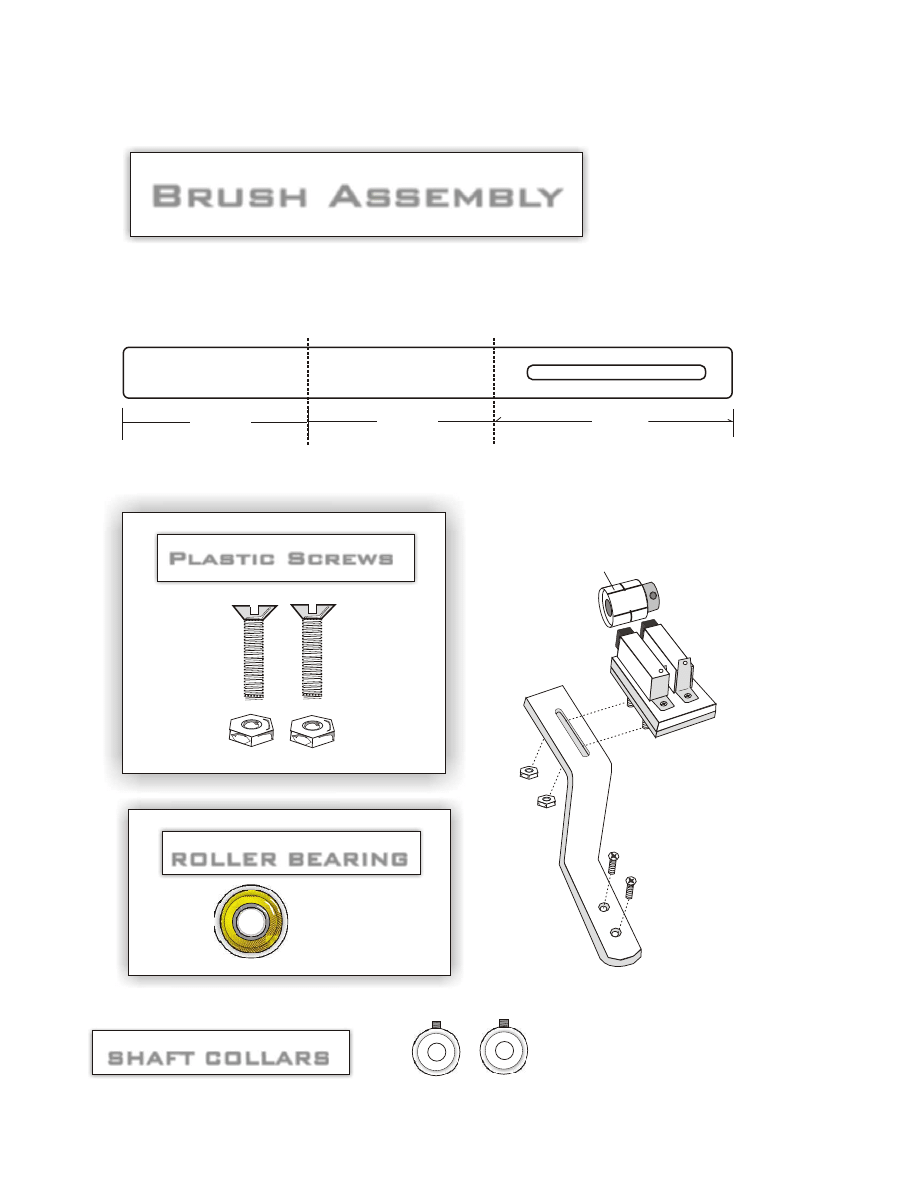
Plastic Bolts
3/4”
Copper Pipe Commutator
separates the brushes
from contacting each other.
Cut all the way around pipe.
Use a very fine hacksaw
blade to cut spacers, fill
spacers with epoxy and
sand smooth.
1 1/8”
1 1/4”
2”
PART “ G”
Type 2 inverter / Brush and commutator assembly
Page 9
Copyright 1996 - 2003 Creative Science & Research
The Capacitor Step up Transformer #363-A
3/4”
separates the brushes
from contacting each other.
Cut all the way around pipe.
Use a very fine hacksaw
blade to cut spacers, fill
spacers with epoxy and
sand smooth.
1 1/8”
Copper Pipe Commutator
J-B Weld or PC 7 Epoxy fill
#1
#2
Back brushes will connect
each capacitor in series to
step up 12 vdc to 120 vdc
Cut Space
Front brushes to charge each capacitor with 12 vdc
Side View
Junction bar that electricity connects
both brushes just as a switch does.
Page 10
Copyright 1996 - 2003 Creative Science & Research
The Capacitor Step up Transformer #363-A
Using a Q-Tip, Grease a piece of card board a little larger than the copper pipe
diameter, this is so the epoxy will not stick to the Card board surface and can be
removed when dry. You now need to fill the copper pipe with Epoxy, so slowly
squeeze out enough J-B Epoxy to fill the inside of the copper pipe, follow all
directions on the J-B Instructions, Mix the 2 parts very well and start placing the
epoxy inside of the copper pipe. Let dry 24 hrs, I prefer to wait 40 hrs, but the
instruction do not tell you that. We use J-B Epoxy because it is the best on the
market and can stand up to 600 degrees.
Now you must find the exact center of the pipe and
score it with a sharp punch. You will be scoring or
punching a small hole into the top of the epoxy. Now
you are going to need a drill press. Place the copper
pipe up as you see in figure #3, Make sure bottom
surface is very flat, if it is not the hole will be crooked
and the commutator will ride with the shaft crooked
and cause a off balance at high speeds. start off with
the smallest drill bit you have and work your way up
until you have a hole the same size as your shaft rods
outer diameter.
STEP FIVE
Now using a fine point marker, mark your cut marks
on the outside of the copper pipe piece. As shown in
figure #4. Use a fine tooth hacksaw to cut.
Cut a long center cut all the way around the copper
pipe leaving a 3/4” space. Cut all the way through the
copper and just up to the hardened epoxy fill. Do not
to deep into the epoxy fill.
3/4”
separates the brushes
from contacting each other.
Cut all the way around pipe.
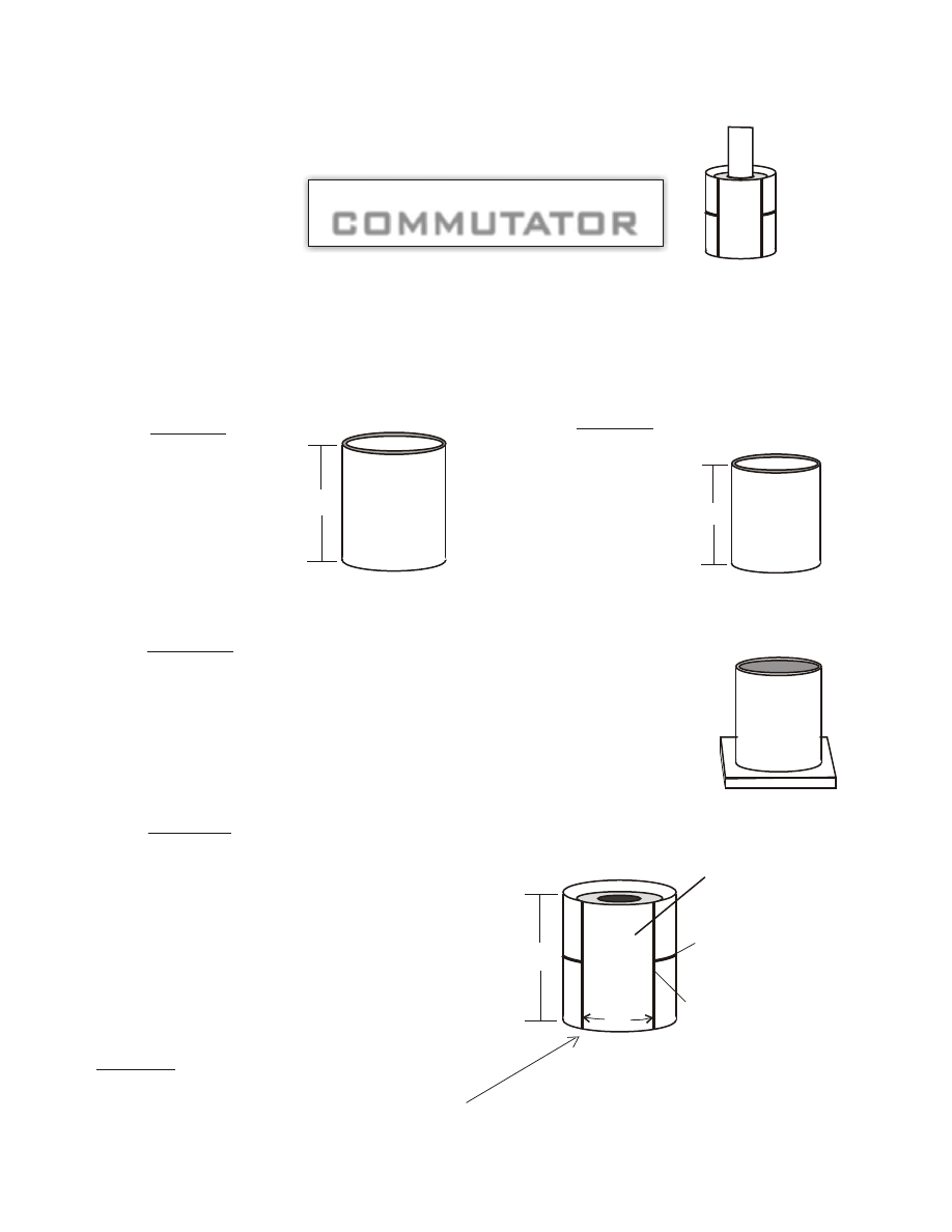
STEP ONE
STEP TWO
STEP THREE
STEP FOUR
Use a very fine hacksaw
blade to cut spacers, fill
spacers with epoxy and
sand smooth.
1 1/8”
1 3/8”
1 3/8”
BUILDING THE
COMMUTATOR
COMMUTATOR
Cut a piece of 3/4”
Diameter” x 1 3/8” length
copper pipe that you can
buy at any hardware store.
Use a pipe cutter to cut a
piece 1 3/8” long.
Next using rough sand
paper, sand the inside of
the copper pipe really
good. And then clean
with laquer thinner.
Surface must be free
from dirt.
This is a homemade Commutator designed by Rick Harrison, This DC Commutator is used to turn off
the incoming DC voltage to the HV Voltage or Low Voltage Magnetic Coil. We are going to create a
junction bar that rotates and as it rotates it will slide onto the 2 carbon DC motor brushes and cause a
complete connection causing DC current to flow into the Electromagnetic coil.
We are going to give you 2 options in making a DC motor commutator. Pick which one is easiest for
you.
Fill in the cuts with epoxy, let dry 24 hrs then sand
down until smooth. Now take a 5/16” steel shaft
and place it back into the epoxy hole, now place a
steel 5/16” shaft collar onto the steel rod and epoxy
it to the end of your new commutator,
( remove the plastic end first. )
OPTION ONE
Figure #3
Acts as a Junction Bar
Figure #4
Page 11
Copyright 1996 - 2003 Creative Science & Research
The Capacitor Step up Transformer #363-A
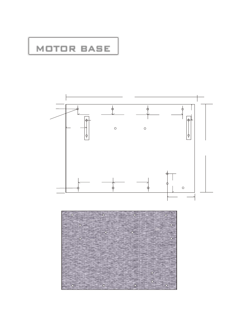
PART “A”
MOTOR BASE
MOTOR BASE
12”
8 ½”
5/16”
5/16”
DRILL SIZE 9/64”
BOLT SIZE IS 6/32 X 3/8”
3/4”
3/4”
3 ½”
3 ½”
3 ½”
3 ½”
3 ½”
2 7/8”
2”
½”
½”
1 7/8”
2 ½”
The base is made of 1/8” aluminum, for a nice looking research prototype we also recommend
½” plexi glass if you do not wish to use the aluminum. If you are having trouble finding
aluminum try your local Machine Shop, for plexi glass ask any Sign shop in your area or check
your local yellow pages under plastics. If you did not purchase a kit from us.
Page 12
Copyright 1996 - 2003 Creative Science & Research
The Capacitor Step up Transformer #363-A
PART “B”
PART “C”
PART “D & E”
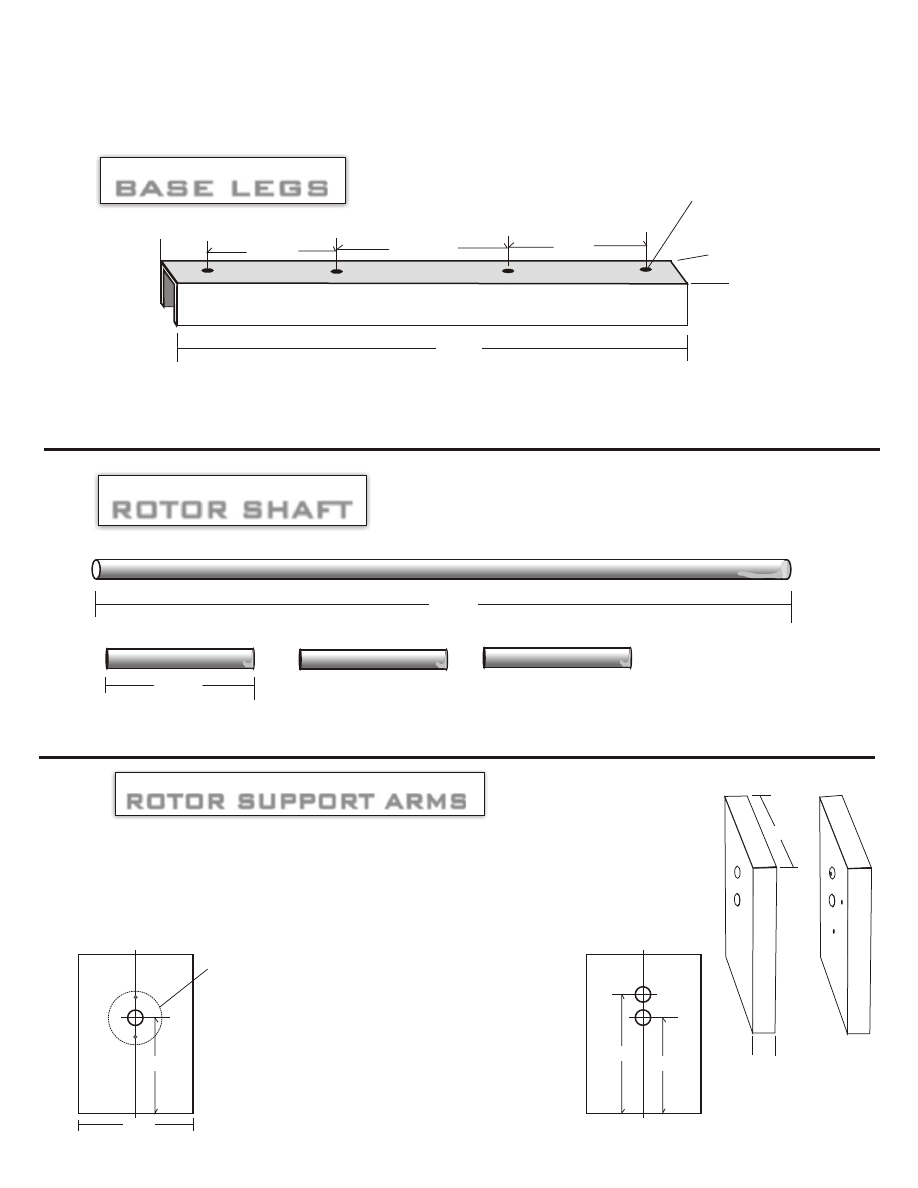
BASE LEGS
BASE LEGS
ROTOR SHAFT
ROTOR SHAFT
ROTOR SUPPORT ARMS
ROTOR SUPPORT ARMS
Page 13
12”
5/8”
3 ½”
3 ½”
3 ½”
3/4”
Aluminum 1/8”channel, check hardware stores, steel suppliers, lumber yards. Drill these holes
at: Drill holes to 7/64”. You will need a qty of - 2. You will need to tap out each hole,
( Thread it ) using a 6-3 NC tap plug style.
Dril holes to: 7/64”
12”
5/16” steel round rod
1 7/8”
You will need three short pieces, two for the magnets to be used as spacers and one for a Shaft mold for making Commutator.
Pa
rt
“
D
“
Pa
rt
“
E
“
½”
2 ½”
Use ½” aluminum bar. Check at: Machine shops, Steel suppliers in your Yellow Pages,
Steel salvage yards etc... Drill two holes on each arm, use a 5/16” drill bit. After you
install roller bearing assembly on part “ D “, remove roller bearing and drill a bigger hole
using a 11/32” drill bit. On Part “ E “ Drill only halfway through, so the 5/16 rotor shaft can
turn on it.
3
3
11/16”
11/16”
4
1/4”
Center
Center
Part “ D “
Part “ E “
Roller bearing assembly, Use a large steel washer, assemble this after you put
the Rotor shaft and arms together Once your shaft is running through Part “ D “
hole, you can then place the Roller bearing onto it. Grease the outer part of the
bearing, Predrill 2 or 3 holes in the large steel washer, place the large washer
over top of the roller bearing, center and mark your holes, use a 7/64” drill bit
and tape out your holes with a 6-3 NC tap, then attach the washer to Part “ D “
with 6-32 x1 ½” bolts. Now mix up some J-B weld or Pc7 Epoxy and fill the
inside beneath the washer and all around the roller bearing. ( Make sure
bearing is greased well so you can remove it to later drill your larger hole.
The reason you need to dril l a larger hole later is so your rotor shaft can turn
more easily. Let epoxy dry for 24 hrs, then remove your Steel washer roller
bearing plate, then remove your roller bearing, drill a bigger hole in Part “D” then
place you bearing back onto the molded roller bearing assembly.
2 ½”
Copyright 1996 - 2003 Creative Science & Research
The Capacitor Step up Transformer #363-A
PART “F”
BRUSH HOLDER
BRUSH HOLDER
Page14
ASSEMBLY
#1
#2
PART “ G”
PART “ G”
1 5/16”
½”
½”
Cut two 1 5/16” x ½” x ½” x 1/16” Square steel.
1 1/4”
1/4”
2”
Fill with PC 7 Epoxy or J - B weld about 1/4” deep.
Brush: grease brush and place inside of square steel part # “F”, Let sit and
dry for 24 hrs, then remove brush and clean it off.
PART “F”
PAR
T “
F”
PAR
T “
F”
PAR
T “
F”
+
+
J - B weld or PC 7 EPOXY
Plastic Separator
5/16” x 1/4” Motor Brush
Copper holding Plate
As an alternative to using brushes, you could replace with heat
treated copper, which has some spring to it. Place the copper on
part “ M “ and bend the copper upward.
+
+
Copyright 1996 - 2003 Creative Science & Research
The Capacitor Step up Transformer #363-A
PART “M”
HOLDING BAR
HOLDING BAR
Brush Assembly
Brush Assembly
Page 15
3” BEND
3” BEND
2 ½”
Use a 8 ½” x 3/4” x 1/16” or best to use 1/8” steel bar. This is used to hold the Brush Assembly.
NOTICE: For a 220 volt dc output simply use two 12 vdc batteries in series and step up.
Commutator
using copper pipe /J-B Weld
Pa
rt
“
M
“
NOTICE: Place brushes in this position,
disregard the brush set up in the color
photo’s.
PARTS “J”
PART “K”
PART “N”
& NUTS
Plastic Screws
Plastic Screws
ROLLER BEARING
ROLLER BEARING
SHAFT COLLARS
SHAFT COLLARS
To attache Brush Assembly to holding bar.
Inner Diameter 5/16
You can buy these
at Graingers.com
or from a skate shop.
You will need a qty of two. The first shaft collar is to hold the shaft into place, allow a 1/8” space or more between collar and Part “D”
The 2nd steel shaft collar is to be epoxied ( Glued ) to one end of the finished commutator.
To fit 5/16” D or buy one and drill it to size 5/16”
Copyright 1996 - 2003 Creative Science & Research
The Capacitor Step up Transformer #363-A
+
_
C
a
p
a
c
ito
r
+
_
C
a
p
a
c
ito
r
+
_
C
a
p
a
c
ito
r
+
_
C
a
p
a
c
ito
r
+
_
C
a
p
a
c
ito
r
Apply a small free energy motor to shaft and turn
LOAD
LOAD or dump cap
Mechanically stepping up a 12 vdc source to 120 vdc
150 or 200 volt capacitor
x 235,000 uf, or you can
connect 20 50 v x 25,000 uf
caps to make a bank. Or you
can simply eliminate the dump
cap(s) and draw straight from
your 10 working caps.( We have
never tried that though.) /
If you wish to make a small watt inverter, simply use smaller
gauge wire and lower rated diodes. The cap dump is optional, we
have tried it on a 100 watt system but have not tried it yet on a
5,000 watt system, we use a dump cap. It is expensive but you
maybe able to simply connect your alternating setup directly to
your work caps. If you do so, you will not need a dump
commutator and brush. This system is very easy to build once you
get the hang of it. Please use extreme caution and keep away
from children and do not forget to always wear rubber gloves.
The motor to turn the shaft and commutators can be a 1 hp 12 dc
free energy or high efficient motor or you can use solar power.
You may want to consider using copper spring brushes as seen on
page 13 they lost longer than carbon brushes. You can then make
5 - 1000 watt inverters and connect them to different breakers in
your house.
12 vdc deep cycle marine
Battery or 2 - 12 vdc batteries
connected in series to get 220 vdc
WARNING HIGH VOLTAGE
Page 16
Copyright 1996 - 2003 Creative Science & Research
The Capacitor Step up Transformer #363-A

100 to 5,000 watt inverter / Type 3
There are many ways in which to build a 500 to 5,000 watt inverter by 60 Hz.
#1. You can buy an ISOLATION TRANSFORMER 115 V input with a 115 V
output. The amperage of the transformer will give you the desired wattage that
you will need. an amperage output voltage of 50 amps should do just fine for a
5,000 watt inverter. you can make your own isolation transformer by simply
taking apart an old wall transformer and rewinding it. ( same amount of winds
for both input and output. ) the size of the wire and how many winds will
determine your wattage. the bigger the diameter of the wire the more wattage,
But if you wind each side with not enough turns you can burn up the wire or it
will get very hot and be less efficient It is best to just buy an ISOLATION
TRANSFORMER. ( Remember an isolation transformer does not step voltage
up or down, if you put 120 volts in you will get 120 volts out.
Now you must take the isolation transformer and apply a 120 volts DC on/off
pulse to the input coil. you should open and shut the + positive side of the 120
vdc at a pulse of 60 times per second. Of course the only way you will know it
is 60 Hz is by using a meter that measures Hz. or you can try running a house
hold appliance that must run on 60 Hz and adjust the pulse speed that way.
So why pulse the input? ( pulsing = on and off )
If you know anything about electronics you will know that when ever you shut
off power to a magnetic coil you will get a reverse polarity! FREE ENERGY
FROM A COLLAPSING MAGNETIC FIELD. and by doing this it will cause
an AC current to flow to the output of the coil. Size of wire and how many
turns you use will determine your output voltage also. If you buy the wrong
transformer and you put 120 VDC into it and your only getting an output
voltage of 108 VAC, then you can add another 12 VDC battery to increase the
input voltage or you can buy and try another ISOLATION TRANSFORMER.
they are not that expensive.
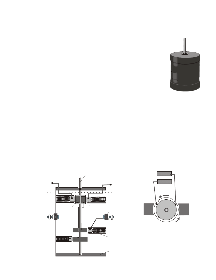
To pulse the input voltage you can use a small DC motor to turn a micro
switch on and off. for our experiments we used a very small low cost, low amp
hobby motor. ( One you would find in toys. ) we then soldered one bead of
solder on one side of it's shaft, But it is best to have two beads. or you can use a
hard metal glue, epoxy etc... to glue two copper or metal BB's to the shaft or
you can use small ball bearings.
Glue
SIDE VIEW
1.5 volt to 6 volt DC electric motor.
bearings or BB'S
Page 17
Copyright 1996 - 2003 Creative Science & Research
The Capacitor Step up Transformer #363-A
SIDE VIEW
TOP VIEW
ISOLATION TRANSFORMER Coil Turns Ratio 1:1
115 V / 115 V x 50 to 100 amps your choice!
Pulsed
120 VDC
1.5 volt to 6 volt DC electric motor.
bearings or BB'S
This small toy motor can be replaced with any size motor you would like to use.
this motor pulsing method will also be used in the #3 method of our invention.
The wattage and amperage you want your inverter to be the more every
component you see below must be heaver duty to match the rated power you are
wanting to draw from the batteries. Otherwise components will get hot and can
burn up.
MICRO
SWITCH
Rated
at
120
VAC
90
amps
+
+
115 VAC to 120 VAC out put
MICRO SWITCH
120 vac 80 AMPS
MICRO SWITCH
120 vac 80 AMPS
SIDE VIEW of a Micro Switch
#1
As the shaft motor rotates counter clock wise, the beads come around and hit the micro switch turning it off or
on, It's best to buy a micro switch that turns on when pushed. you can also build your own contacts instead of
buying a switch. You simply build one using the contact method that you will see in #3. you can use nuts and
bolt heads as the contacts, this will increase your amperage rating to a high level, of course if you are an
electrical engineer you can clearly see that you can use our methods of stepping up voltage and apply them to
solid state circuitry. These plans are intended for those who are not educated in electronic engineering.
Page 18
Copyright 1996 - 2003 Creative Science & Research
The Capacitor Step up Transformer #363-A

An Isolation Transformer can be used but it is not very efficient yet at this point, As you read on
we will show even better ways of making very powerful inverters or even DC step up capacitor
transformers, which can also be used as a high or low wattage inverter.
Please build your inverter in a safe container, such as plastic or plywood.
Better yet do what we did, we used an old computer box. Try your best to be neat
about what you are doing. take your time, do not rush it.
HIGH VOLTAGE CAN KILL YOU! Use rubber gloves! Keep away from children.
The following is an example of how to make a simple capacitor inverter, which can also
be used as a DC stepup capacitor type transformer!
Invented by: David Waggoner of Creative Science & Research
WARNING!
WARNING!
Our Step Up Capacitor Inverter
This type of inverter is unlike any you have ever seen before, Although capacitors are used
widely in commercial inverters all over the world, We designed this system especially for the
back yard researcher in mind, it is simple, low cost compared to buying a $3,000 commercial
inverter. You may already have all the parts you need at home in your shop. this type of
inverter will use 24 volts DC or you can add more capacitors to allow it to run on 12 volts
DC. but for example we will show you the 24 volt DC method only. 24 volts DC is much
more safer than using 120 volts DC. there is much less chance of a spark igniting the
hydrogen gases and less chance of someone getting shocked to death!
If you do not now what a capacitor is then do not build this inverter yet. Go down to your
local Radio Shack and buy a $4 beginners book on electronics called: GETTING STARTED
IN ELECTRONICS, ( Page 32 ) This book will also teach you what an SCR is. Most of
the parts can be purchased at Radio Shack or purchased by mail catalogs: call these 2
company's and ask them to send you a free catalog. HOSFELT Electronics inc. 1-800- 524-
6464 or ALL ELECTRONICS CORP. 1-800-826-5432 Peerless Electronics 1815 s. 7th St.
Louisville, KY. 40208 502-637-7674
SO HOW DOES IT WORK?
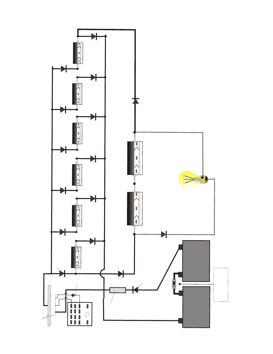
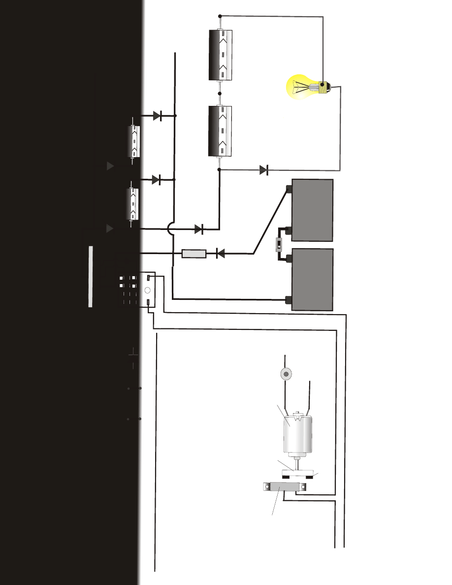
First of all we start with 2 deep cycle marine batteries connected in series to get 24 volts dc.
Now we must take that 24 vdc and step it up to 144 vdc, and we will do that by using our new
method of using capacitors as batteries, put together in series, EXAMPLE: Charging and
using 2 capacitors; ( see page 19 ) Charge #1 capacitor with 24 vdc and charge #2 capacitor
with 24 vdc, Now remove the charge and each capacitor now has a full charge of 24 vdc. (
Each capacitor should be taped to your table for this experiment.) now using one alligator
clip or wire, connect the + to the - as you would 2 batteries and you will now double the
voltage from 24 vdc to 48 vdc. BE CAREFUL DO NOT TOUCH THE ENDS OF THE
CAPACITORS. YOU MUST DISCHARGE ALL CAPACITORS WITH A WIRE BY
SHORTING THEM OUT OR BY CONNECTING A LOAD SUCH AS A 100 WATT
LIGHT BULB.
USING A 24 VDC INPUT
Page 19
Copyright 1996 - 2003 Creative Science & Research
The Capacitor Step up Transformer #363-A
Please read this it is very important! YOU CAN NOT CHARGE EACH CAPACITOR WITH 24
VDC AND ALSO HAVE THEM CONNECTED IN SERIES ! You must do one or the other never
at the same time! 1st you charge each capacitor, then 2nd you disconnect that
charge, 3rd you then connect each capacitor ( that now has that powerful 24 volt
charge ) and connect them in series. now it would be stupid to connect and disconnect
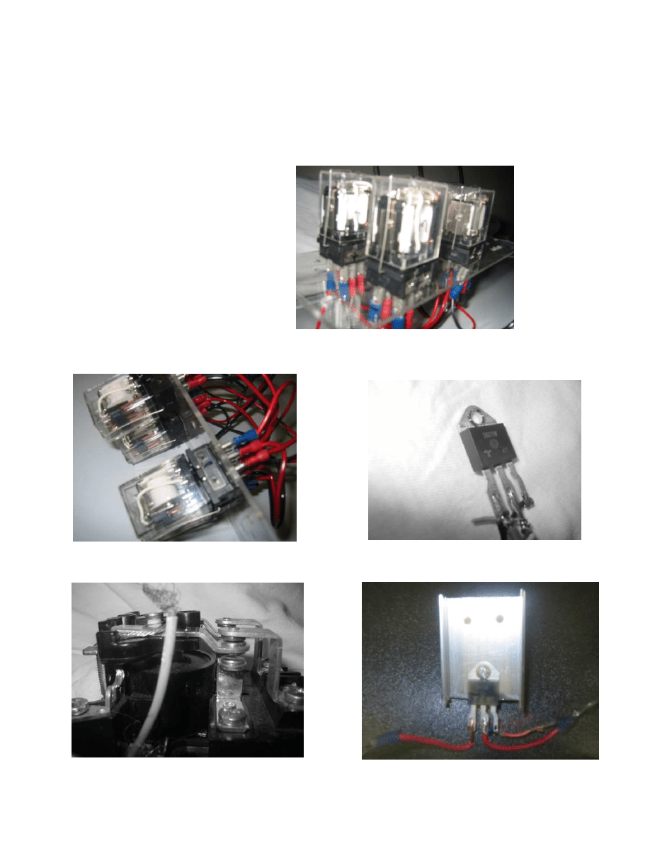
all of this by hand. So what you must do is use switches! You can use all relay switches
1- 4 pole double throw and 5 - 30 amp auto relay switches, or you can use 1- 4 pole
double throw relay and 5 - SCR's (Silicon-Controlled Rectifiers.) as switches. ( It is very
easy to do!) Using SCR's is much quieter than using loud relays. you can buy low power
SCR's at Radio Shack or you can buy High amperage SCR's by catalog. use 70 amp x
200v SCR's for a 1,000 watt unit, or 275 amp x 600 volt SCR's for a 5,000 watt unit.
FIGURE #1 is the Charging diagram, this is where you will need to use the 4 pole double
throw relay w/1-70 amp SCR on the positive lead, ( Radio Shack type cat. no. 275-214
12 vdc plug in relay. ) This relay is always in the up position, so the capacitors will be
charging as soon as you connect the battery to the relay, then when you apply 12 vdc to
the coil of the 4 PDT relay it will move the contacts down and this will turn off the charge.
All of this will happen very quickly! Because instead of connecting the relay coil to the 12
vdc battery by hand you will be using our MOTOR MICRO SCR SWITCH METHOD The
switching must be fast in order to charge the main capacitor bank, which you can apply
your load to this, such as a 100 watt light bulb etc... DC only at this point. So you see
what we are doing here is eliminating the need to place 10 - 12 vdc deep cycle
batteries in series to get 120 vdc. we are simply using capacitors instead. But remember
no matter what you do you will always need 10 deep cycle batteries for any average size
home. NOTE: You could also build your own relay and use large bolt heads for contacts,
and make your own 60 amp 4 PDT contact relay. But its not advisable, Using SCR's as
switches work much better!
12 VDC coil 75 ma
electromagnet
SPRING
CONTACTS
SIDE VIEW OF 4 PDT RELAY
FRONT VIEW OF RELAY
COIL 12 v INPUT +
1 2 3 4
5 6 7 8
9 10 11 12
13
14
+
_
25000 uf 50v
25000 uf 50v
Electrolytic Capacitor
CONNECT WIRE
AFTER CHARGE
OUTPUT
Electrolytic Capacitor
Charged to 24 vdc
Charged to 24 vdc
+
+
_
sw
_
48 vdc
We Strongly Recommend that you Build a 100 watt inverter first using relays. Use 120 VDC to light a bulb!
THIS IS WHAT A RELAY LOOKS LIKE
Page 20
Copyright 1996 - 2003 Creative Science & Research
The Capacitor Step up Transformer #363-A
fig
#
1
#
5
7
9
C
H
A
R
G
IN
G
C
IR
C
U
IT
D
IA
G
R
A
M
#
2
C
H
A
R
G
IN
G
C
A
P
B
A
N
K
#
3
TH
E
M
A
IN
C
A
PA
C
IT
O
R
B
A
N
K
2
5
0
0
0
U
F
5
0
V
E
le
c
tr
o
ly
tic
C
a
p
a
c
ito
r
+
_
2
5
0
0
0
u
F
5
0
V
+
_
2
5
0
0
0
u
F
5
0
V
+
_
2
5
0
0
0
u
F
5
0
V
+
_
2
5
0
0
0
u
F
5
0
V
+
_
2
5
0
0
0
u
F
5
0
V
+
_
2
5
0
0
0
u
F
5
0
V
5
0
v
E
le
c
tr
o
ly
tic
c
a
p
+
_
2
5
0
0
0
u
F
5
0
V
5
0
v
E
le
c
tr
o
ly
tic
c
a
p
+
_
+
#
1
1
2
3
4
9
1
0
1
1
1
2
+
_
+
+
1
2
V
D
C
D
EE
P
C
YC
LE
B
A
TT
ER
Y
1
2
V
D
C
D
EE
P
C
YC
LE
B
A
TT
ER
Y
_
6
0
A
M
P
A
U
TO
FU
SE
1
0
0
A
M
P
1
5
0
V
-
2
0
0
V
D
IO
D
E
Pl
e
a
se
n
o
te
t
h
a
t
SM
A
LL
ER
D
io
d
e
s
c
a
n
b
e
c
o
n
n
e
c
te
d
a
n
d
s
ta
c
ke
d
in
p
a
ra
lle
l t
o
in
c
re
a
se
in
p
u
t a
m
p
s.
R
a
d
io
S
h
a
c
k
p
a
rt
#
2
7
5
-
2
1
4
1
2
V
D
C
p
lu
g
-
in
r
e
la
y.
c
o
n
ta
c
ts
r
a
te
d
a
t:
5
A
a
t
1
2
5
v
++
++
__
__
YO
U
M
U
ST
U
SE
A
D
IO
D
E
F
O
R
L
O
A
D
o
r
fo
r
n
e
xt
a
lte
rn
a
tin
g
c
u
rre
n
t
p
h
a
se
.
1
2
0
V
D
C
O
U
TP
U
T
a
t
th
is
p
o
in
t.
1
0
0
w
a
tt
li
g
h
t
b
u
lb
Th
is
is
t
h
e
c
h
a
rg
in
g
c
irc
u
it,
r
e
la
y
is
in
t
h
e
u
p
p
o
si
tio
n
a
n
d
c
h
a
rg
in
g
e
a
c
h
c
a
p
a
c
ito
r.
B
e
s
u
re
t
o
u
se
1
1
5
v
a
c
e
xt
e
n
si
o
n
c
o
rd
w
ire
,
8
a
m
p
o
r
m
o
re
.
Th
e
m
o
re
y
o
u
st
a
c
k
th
e
se
in
p
a
ra
lle
l t
h
e
m
o
re
w
a
tt
a
g
e
y
o
u
w
ill
g
e
t,
a
n
d
y
o
u
w
ill
a
ls
o
n
e
e
d
t
o
u
se
t
h
e
p
ro
p
e
r
w
ire
si
ze
t
o
h
a
n
d
le
t
h
e
a
m
p
e
ra
g
e
c
o
m
in
g
t
h
ro
u
g
h
.
if
w
ire
is
g
e
tt
in
g
a
lm
o
st
h
o
t
o
r
e
ve
n
w
a
rm
re
p
la
c
e
2
4
v
o
lt
d
c
i
n
p
u
t
D
o
n
o
t
a
p
p
ly
l
o
a
d
t
o
#
2
c
h
a
rg
e
b
a
n
k
.
O
n
ly
T
o
#
3
b
a
n
k
!
T
R
O
U
B
LE
SH
O
O
TI
N
G
:
If
yo
u
h
a
ve
a
p
ro
b
le
m
w
ith
t
h
e
#
2
c
a
p
a
c
ito
r
b
a
n
k
sh
u
tt
in
g
d
o
w
n
.
Th
e
n
a
b
a
c
k
c
a
la
p
se
h
a
s
h
a
p
p
e
n
e
d
a
n
d
y
o
u
w
ill
n
e
e
d
t
o
r
e
c
h
a
rg
e
e
a
c
h
c
a
p
a
c
ito
r
a
g
a
in
a
n
d
t
h
e
n
g
o
t
o
e
a
c
h
o
n
e
a
n
d
d
is
c
h
a
rg
e
it
w
ith
a
d
is
c
h
a
rg
in
g
w
ire
.
(
SH
O
R
T
TH
E
M
O
U
T
)
if
t
h
is
d
o
e
s
n
o
t
h
e
lp
t
ry
it
a
g
a
in
.
if
th
a
t
st
ill
d
o
e
s
n
o
t
h
e
lp
y
o
u
w
ill
h
a
ve
t
o
t
a
ke
a
p
a
rt
e
a
c
h
c
a
p
a
c
ito
r
fr
o
m
o
n
e
a
n
o
th
e
r
a
n
d
c
h
a
rg
e
a
n
d
d
is
c
h
a
rg
e
a
g
a
in
.
T
h
e
c
a
p
a
c
ito
rs
a
re
s
til
l g
o
o
d
.
T
h
is
s
h
o
u
ld
n
e
ve
r
h
a
p
p
e
n
o
n
c
e
y
o
u
h
a
ve
e
ve
ry
th
in
g
in
p
la
c
e
a
n
d
C
A
G
R
1
4
0
0
O
H
M
T
O
P
V
IE
W
A
lu
m
in
u
m
H
e
a
t
Si
n
k
w
/
SC
R
2
0
0
a
m
p
U
se
1
0
0
a
m
p
d
io
d
e
s
x
1
5
0
t
o
2
0
0
v
o
lts
3
0
t
o
6
0
a
m
p
c
irc
u
it
b
re
a
ke
r
h
o
u
se
t
yp
e
.
Page 21
fig
#
2
C
H
A
R
G
IN
G
C
IR
C
U
IT
D
IA
G
R
A
M
A
LL
C
O
N
N
E
C
TI
O
N
S
M
U
ST
B
E
S
O
LD
E
R
E
D
W
E
LL
C
o
n
tin
u
e
d
f
ro
m
p
a
g
e
1
0
f
ig
#
1
N
o
w
i
t
is
t
im
e
to
c
o
n
n
ec
t
th
e
p
u
ls
er
m
o
to
r
sw
it
ch
.
T
h
is
i
s
o
n
/
o
ff
s
et
u
p
u
si
n
g
a
s
m
al
l
re
ed
s
w
it
ch
,
(
D
o
o
r
al
ar
m
s
w
it
ch
)
it
w
il
l
b
e
u
se
d
t
o
t
u
rn
p
o
w
er
o
n
a
n
d
o
ff
t
o
t
h
e
re
la
y
c
o
il
,
th
is
w
il
l
ca
u
se
t
h
e
el
ec
tr
o
m
ag
n
et
t
o
c
o
m
e
o
n
a
n
d
o
ff
,
th
is
w
il
l
al
so
ca
u
se
t
h
e
co
n
ta
ct
a
rm
t
o
m
o
v
e
u
p
a
n
d
d
o
w
n
.
S
ee
a
ls
o
p
ag
e
6
an
d
7
.
S
o
w
h
en
t
h
e
re
la
y
c
o
il
i
s
o
ff
t
h
e
ca
p
ac
it
o
rs
a
re
ch
ar
g
in
g
,
a
n
d
w
h
en
i
t
is
o
n
,
it
m
o
v
es
t
h
e
co
n
ta
ct
a
rm
d
o
w
n
an
d
d
is
co
n
n
ec
ts
t
h
e
2
4
v
d
c
b
at
te
ry
s
o
i
t
w
il
l
n
o
l
o
n
g
er
c
h
ar
g
e.
N
o
w
w
h
en
i
t
is
i
n
t
h
e
d
o
w
n
p
o
si
ti
o
n
,
it
w
il
l
tu
rn
o
n
t
h
e
p
o
w
er
to
t
h
e
5
s
m
al
l
re
ed
r
el
ay
s
in
F
ig
#
3
.
C
au
si
n
g
al
l
5
S
C
R
's
t
o
S
O
W
H
A
T
D
O
E
S
S
T
A
C
K
IN
G
M
E
A
N
?
I
t
m
ea
n
s
ju
st
w
h
at
i
t
so
u
n
d
s
li
k
e,
y
o
u
s
ta
ck
I
n
p
ar
al
le
l.
I
f
y
o
u
h
av
e
a
h
ar
d
t
im
e
in
y
o
u
r
ar
ea
f
in
d
in
g
ca
p
ac
it
o
rs
o
r
d
io
d
es
t
h
at
a
re
r
at
ed
t
h
at
h
ig
h
t
h
en
y
o
u
c
an
b
u
y
c
h
ea
p
o
n
es
an
d
s
ta
ck
t
h
em
.
it
s
m
u
ch
e
as
ie
r
th
o
u
g
h
i
f
y
o
u
b
u
y
t
h
e
ra
ti
n
g
y
o
u
n
ee
d
.
ex
am
p
le
;
st
ac
k
e
ac
h
d
io
d
e
o
r
ca
p
ac
it
o
r
o
n
t
o
p
o
f
th
e
o
th
er
a
n
d
c
o
n
n
ec
t
th
em
i
n
p
ar
al
le
l.
E
x
am
p
le
:
I
f
y
o
u
s
ta
ck
2
-
3
5
a
m
p
x
1
5
0
v
d
io
d
es
i
n
p
ar
al
le
l
y
o
u
w
il
l
g
et
a
7
0
a
m
p
o
u
tp
u
t.
t
h
e
sa
m
e
w
it
h
c
ap
ac
it
o
rs
.
y
o
u
d
o
u
b
le
y
o
u
r
am
p
er
ag
e
an
d
w
at
ta
g
e.
D
IO
D
ES
Sy
m
b
o
l f
o
r
D
io
d
e
s
SI
D
E
V
IE
W
SM
A
LL
R
A
R
E
E
A
R
TH
M
A
G
N
E
TS
G
lu
e
t
o
a
lu
m
in
u
m
-e
p
o
xy
1
2
V
D
C
in
p
u
t
fr
o
m
o
n
e
o
f
th
e
b
a
tt
e
rie
s
1
.5
v
o
lt
to
6
v
o
lt
D
C
e
le
c
tr
ic
m
o
to
r.
SM
A
LL
A
LU
M
IN
U
M
B
LO
C
K
G
LU
E
TO
S
H
A
FT
-
E
P
O
X
Y
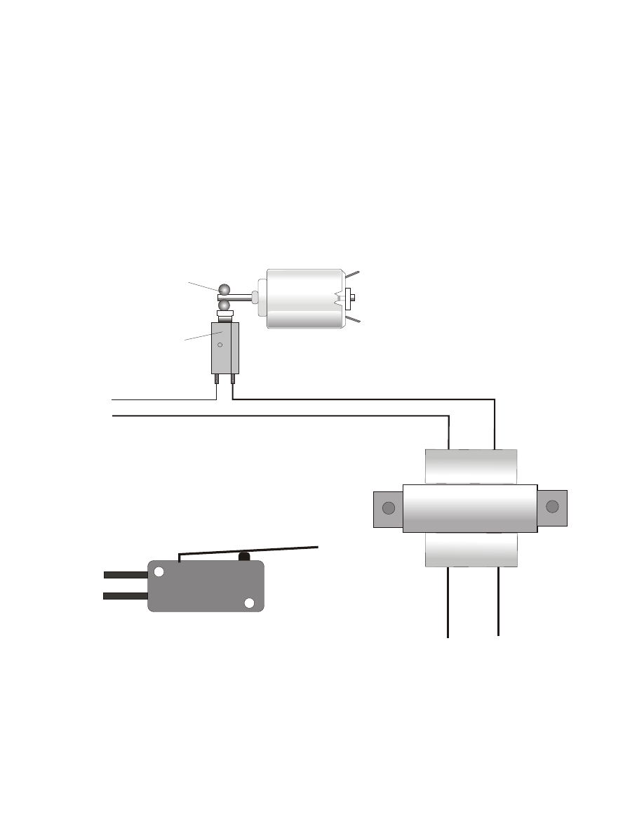
Th
is
w
ire
c
a
n
b
e
s
m
a
ll,
It
o
n
ly
t
a
ke
s
a
b
o
u
t
7
0
m
a
to
r
u
n
t
h
e
c
o
il
o
f
th
e
r
e
la
y.
R
e
e
d
s
w
itc
h
/
R
a
d
io
Sh
a
c
k
a
la
rm
s
w
itc
h
ty
p
e
-f
o
r
d
o
o
r
a
la
rm
s.
+
_
+
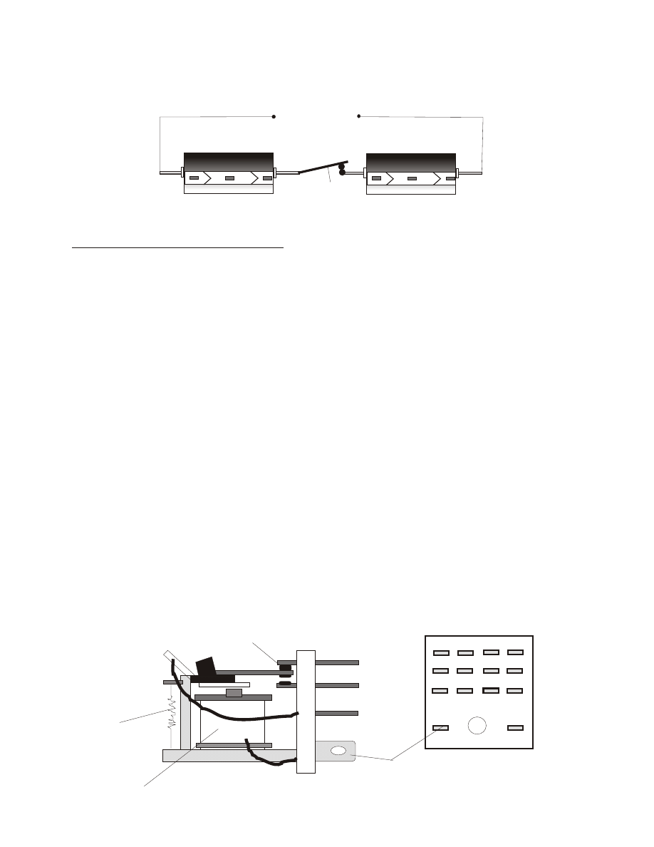
A
s
th
e
sh
af
t
m
o
to
r
ro
ta
te
s
co
u
n
te
r
cl
o
ck
w
is
e,
t
h
e
m
ag
n
et
c
o
m
es
a
ro
u
n
d
a
n
d
t
u
rn
s
o
n
t
h
e
re
ed
sw
it
ch
t
u
rn
in
g
i
t
o
ff
a
n
d
o
n
,
y
o
u
c
an
re
p
la
ce
th
is
p
u
ls
e
re
ed
a
n
d
m
o
to
r
sw
it
ch
w
it
h
a
n
e
le
ct
ro
n
ic
o
n
/
o
ff
s
y
st
em
.
(
a
p
u
ls
er
g
en
er
at
o
r
)
(
i
t
is
i
n
t
h
e
el
ec
tr
o
n
ic
s
b
eg
in
n
er
s
b
o
o
k
I
t
o
ld
y
o
u
a
b
o
u
t
ea
rl
ie
r.
b
y
b
u
il
d
in
g
a
n
e
le
ct
ro
n
ic
o
n
/
o
ff
p
u
ls
er
t
o
r
ep
la
ce
t
h
e
R
ee
d
S
w
it
ch
,
th
e
u
n
it
w
il
l
b
e
m
u
ch
q
u
ie
te
r.
A
ls
o
p
la
ce
m
an
u
al
o
n
/
o
ff
s
w
it
ch
es
w
h
er
e
n
ee
d
ed
s
o
y
o
u
c
an
p
o
w
er
u
p
y
o
u
r
in
v
er
te
r
an
d
t
u
rn
i
t
o
ff
.
Y
o
u
w
il
l
ac
tu
al
ly
n
ee
d
2
r
ee
d
an
d
m
o
to
r
sw
it
ch
es
,
th
is
o
n
e
is
t
h
e
fi
rs
t.
a
n
d
t
h
e
2
n
d
o
n
e
is
u
se
d
f
o
r
al
te
rn
at
in
g
t
h
e
d
c
to
a
c
u
si
n
g
an
o
th
er
r
el
ay
a
n
d
2
0
0
a
m
p
S
C
R
's
.
it
i
s
al
l
re
al
ly
v
er
y
s
im
p
le
a
n
d
n
o
t
th
at
h
ar
d
o
r
ex
p
en
si
v
e
to
b
u
il
d
.
1
a
m
p
d
io
d
e
V
a
ria
b
le
r
e
si
st
o
r
sp
e
e
d
w
itc
h
#
3
TH
E
M
A
IN
C
A
PA
C
IT
O
R
B
A
N
K
2
5
0
0
0
U
F
5
0
V
E
le
c
tr
o
ly
tic
C
a
p
a
c
ito
r
+
_
2
5
0
0
0
u
F
5
0
V
+
_
2
5
0
0
0
u
F
5
0
V
5
0
v
E
le
c
tr
o
ly
tic
c
a
p
+
_
2
5
0
0
0
u
F
5
0
V
5
0
v
E
le
c
tr
o
ly
tic
c
a
p
+
_
+
#
1
1
2
3
4
9
1
0
1
1
1
2
+
_
+
+
1
2
V
D
C
D
EE
P
C
YC
LE
B
A
TT
ER
Y
1
2
V
D
C
D
EE
P
C
YC
LE
B
A
TT
ER
Y
_
++
++
__
__
YO
U
M
U
ST
U
SE
A
D
IO
D
E
F
O
R
L
O
A
D
o
r
fo
r
n
e
xt
a
lte
rn
a
tin
g
c
u
rre
n
t
p
h
a
se
.
1
2
0
V
D
C
O
U
TP
U
T
a
t
th
is
p
o
in
t.
1
0
0
w
a
tt
li
g
h
t
b
u
lb
2
4
v
o
lt
d
c
i
n
p
u
t
C
A
G
U
se
1
0
0
a
m
p
d
io
d
e
s
x
1
5
0
to
2
0
0
v
o
lts
W
e
a
re
t
ry
in
g
t
o
m
a
ke
t
h
is
s
im
p
le
s
o
a
n
yo
n
e
c
a
n
b
u
ild
t
h
is
.
If
it
is
s
til
l
to
m
u
c
h
f
o
r
yo
u
.
w
e
a
re
s
o
rr
y
w
e
h
a
ve
d
o
n
e
t
h
e
b
e
st
w
e
c
a
n
f
o
r
n
o
w
.
T
H
E
O
N
/O
F
F
P
U
L
S
E
R
S
W
IT
C
H
F
O
R
R
E
L
A
Y
+
Page 22
The following page shows the use of SCR’s to connect the charged capacitors in series to step up the
incoming 12 vdc or 24 vdc current.
Please notice that you can use 4 PDT relays to do the same thing which we have fully tested and found
the relays do great! We have not fully tested the SCR’s yet, but we have done some bench test’s and the
SCR’s look like they will work just fine. If they do not you may know of a better way, please let us
know because we do not have the time right now to test and develop the use of SCR’s, We are working
on more important projects.
Thank you
David Waggoner
Tesla@fuellesspower.com
Low amp 4PDT Relay Switches
Low amp 4PDT Relay Switches
SCR’s High amp for switching
SCR’s High amp w/heat sink aluminum
High Amp 4PDT Relay SW
Page 23
fig
#
3
C
O
N
N
E
C
TI
N
G
C
A
P
S
I
N
S
E
R
IE
S
FR
O
N
T
V
IE
W
O
F
R
E
LA
Y
#
1
2
5
0
0
0
u
f
5
0
v
E
le
c
tr
o
ly
tic
C
a
p
a
c
ito
r
C
a
se
t
yp
e
w
ill
b
e
m
u
c
h
la
rg
e
r
w
ith
b
o
lt
ty
p
e
c
o
n
n
e
c
to
rs
.
+
_
2
5
0
0
0
u
f
5
0
v
+
_
2
5
0
0
0
u
f
5
0
v
+
_
2
5
0
0
0
u
f
5
0
v
+
_
2
5
0
0
0
u
f
5
0
v
+
_
2
5
0
0
0
u
f
5
0
v
+
_
1
2
3
4
5
6
9
1
0
1
1
1
2
+
_
+
+
_
_
R
a
d
io
S
h
a
c
k
p
a
rt
#
2
7
5
-
2
1
4
1
2
V
D
C
p
lu
g
-
in
r
e
la
y.
c
o
n
ta
c
ts
r
a
te
d
a
t:
5
A
a
t
1
2
5
v
++
__
C
A
N
o
w
a
s
se
en
i
n
p
ag
e
1
1
,
W
h
en
t
h
e
re
la
y
i
s
tu
rn
ed
o
n
,
th
e
re
la
y
a
rm
w
il
l
m
o
v
e
d
o
w
n
a
n
d
o
u
t
o
f
ch
ar
g
in
g
p
o
si
ti
o
n
a
n
d
w
il
l
m
o
v
e
to
#
5
a
n
d
#
9
r
el
ay
p
o
si
ti
o
n
a
s
sh
o
w
n
,
th
is
w
il
l
sw
it
ch
o
n
t
h
e
S
C
R
'S
,
an
d
w
il
l
co
n
n
ec
t
ea
ch
2
4
v
o
lt
c
h
ar
g
ed
c
ap
ac
it
o
r
in
se
ri
es
a
n
d
g
iv
e
y
o
u
a
n
o
u
tp
u
t
o
f
1
4
4
v
o
lt
s.
A
g
ai
n
t
h
is
w
il
l
ch
ar
g
e
#
3
T
h
e
M
ai
n
C
ap
ac
it
o
r
B
an
k
(
a
s
se
en
o
n
p
ag
e
1
3
.
)
Y
o
u
ca
n
r
ep
la
ce
w
it
h
1
2
v
d
c
3
0
a
m
p
au
to
r
el
ay
s.
b
u
t
is
n
o
t
ad
v
is
ab
le
W
A
R
N
IN
G
:
n
ev
er
c
h
ar
g
e
an
d
t
u
rn
o
n
t
h
e
S
C
R
's
a
t
th
e
sa
m
e
ti
m
e!
It
w
il
l
b
u
rn
u
p
y
o
u
r
S
C
R
's
.
T
h
is
i
s
w
h
y
w
e
u
se
a
r
el
ay
s
w
it
ch
#
1
.
E
v
en
t
h
o
u
g
h
t
h
e
re
la
y
w
il
l
b
e
sw
it
ch
in
g
v
er
y
f
as
t,
t
h
e
ch
ar
g
in
g
a
n
d
t
h
e
S
C
R
's
w
il
l
b
e
o
n
a
t
d
if
fe
re
n
t
ti
m
es
.
I
f
y
o
u
a
re
g
o
in
g
t
o
b
u
il
d
a
n
i
n
v
er
te
r
th
at
u
se
s
m
u
ch
l
es
s
w
at
ta
g
e,
T
h
en
ag
ai
n
a
ll
o
f
th
es
e
p
ar
ts
c
an
b
e
p
u
rc
h
as
ed
a
t
an
y
R
ad
io
S
h
ac
k
s
to
re
.
N
o
te
:
F
o
r
th
o
se
o
f
y
o
u
w
h
o
d
o
n
o
t
k
n
o
w
w
h
at
a
n
S
C
R
i
s,
I
t
is
a
S
il
ic
o
n
-C
o
n
tr
o
ll
ed
R
ec
ti
fi
er
.
Y
o
u
c
an
m
o
v
e
a
la
rg
e
am
o
u
n
t
o
f
cu
rr
en
t
w
it
h
j
u
st
a
v
er
y
s
m
al
l
am
o
u
n
t
o
f
cu
rr
en
t
ju
st
i
n
t
h
e
m
il
li
am
p
s,
t
o
t
u
rn
o
n
t
h
e
sw
it
ch
t
o
a
ll
o
w
t
h
e
v
er
y
l
ar
g
e
cu
rr
en
t
to
f
lo
w
.
Y
o
u
c
an
b
u
y
6
a
m
p
S
C
R
's
a
t
R
ad
io
S
h
ac
k
,
P
la
y
w
it
h
th
es
e
fi
rs
t,
a
n
d
l
ea
rn
a
n
d
t
h
en
b
u
y
t
h
e
ex
p
en
si
v
e
S
C
R
's
t
h
at
y
o
u
w
il
l
n
ee
d
f
o
r
5
,0
0
0
w
at
ts
.
B
u
y
2
7
5
a
m
p
X
6
0
0
v
o
lt
S
C
R
's
fo
r
a
5
,0
0
0
w
at
t
u
n
it
.
L
o
o
k
i
n
y
o
u
r
y
el
lo
w
p
ag
e
p
h
o
n
e
b
o
o
k
f
o
r
el
ec
tr
o
n
ic
s
u
p
p
li
er
s.
I
fo
u
n
d
2
7
5
a
m
p
S
C
R
's
a
s
lo
w
a
s
$
6
0
ea
.
T
h
es
e
ca
p
ac
it
o
rs
a
re
t
h
e
sa
m
e
ca
p
ac
it
o
rs
a
s
se
en
o
n
p
ag
e
1
0
,
w
e
d
id
n
o
t
d
ra
w
i
n
t
h
e
o
th
er
c
h
ar
g
in
g
c
o
n
n
ec
ti
o
n
s
so
y
o
u
w
o
u
ld
n
o
t
g
et
co
n
fu
se
d
,
I
t
w
o
u
ld
l
o
o
k
l
ik
e
a
b
u
n
ch
o
f
sp
ag
h
et
ti
,
o
f
co
u
rs
e
th
is
c
ir
cu
it
an
d
t
h
e
ci
rc
u
it
o
n
p
ag
e
1
0
w
il
l
al
l
b
e
h
o
o
k
ed
t
o
g
et
h
er
,
It
w
il
l
b
e
th
e
jo
b
o
f
th
e
4
P
D
T
re
la
y
t
o
k
ee
p
t
h
em
s
ep
ar
at
e.
W
e
ar
e
tr
y
in
g
t
o
m
ak
e
th
is
a
s
si
m
p
le
f
o
r
ev
er
y
o
n
e
as
p
o
ss
ib
le
T
h
is
t
y
p
e
o
f
st
ep
u
p
t
ra
n
sf
o
rm
er
/
i
n
v
er
te
r
w
o
rk
s
v
er
y
w
el
l.
th
e
ca
p
ac
it
o
rs
a
n
d
d
io
d
es
w
il
l
la
st
a
l
if
e
ti
m
e!
C
C
=
C
a
th
o
d
e
,
A
=
A
n
o
d
e
,
G
=
G
a
te
.
S
e
e
R
a
d
io
S
h
a
c
ks
g
e
tt
in
g
s
ta
rt
e
d
in
e
le
c
tr
o
n
ic
s
b
o
o
k.
it
w
ill
t
e
ll
yo
u
a
b
o
u
t
SC
R
's
2
7
5
a
m
p
s
x
3
0
0
-
6
0
0
v
TO
-2
2
0
c
a
se
o
r
w
h
a
t
e
ve
r
yo
u
r
su
p
p
ly
h
o
u
se
h
a
s.
H
o
le
fo
r b
o
lt
a
nd
n
ut
to
a
tta
c
h
to
a
lu
m
in
um
h
e
a
t s
in
k.
he
a
t s
in
k
c
a
n
b
e
s
q
ua
re
o
r a
ny
s
iz
e
y
o
u
w
a
nt
, i
t i
s
th
e
re
to
h
e
lp
ke
e
p
th
e
S
C
R'
s
c
o
o
l.
SC
R
A
G
1
2
v
d
c
FA
N
+
-
D
io
d
e
R
a
te
d
2
0
0
a
m
p
b
y
2
0
0
-
6
0
0
v
o
lt
(
Yo
u
r
C
h
o
ic
e
)
Sm
a
ll
M
ill
ia
m
p
R
e
e
d
R
e
la
y
Sw
itc
h
1
2
v
d
c
SP
ST
+
-
To
1
2
v
d
c
B
a
tt
e
ry
A
lu
m
in
u
m
H
e
a
t
Si
n
k
SC
R
2
7
5
a
m
p
s
x
3
0
0
t
o
6
0
0
v
4
0
0
t
o
5
0
0
o
h
m
r
e
si
st
o
r
C
A
G
+
C
A
G
+
C
A
G
+
C
A
G
+
C
A
G
+
Yo
u
r
SC
R
M
a
y
lo
o
k
So
m
e
th
in
g
lik
e
t
h
is
.
D
e
p
e
n
d
in
g
o
n
w
h
a
t
si
ze
y
o
u
b
u
y.
E
xa
m
p
le
o
n
ly
To
p
V
ie
w
S
id
e
V
ie
w
C
o
p
yr
ig
h
t
1
9
9
8
Pa
te
n
t
Pe
n
d
in
g
LO
W
C
O
ST
.6
9
Page 24
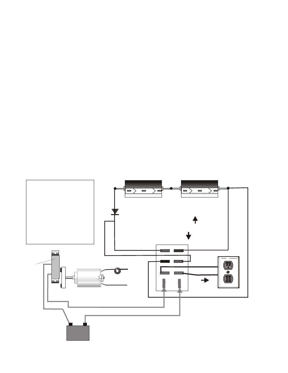
For low wattage applications try this below.. For High wattage use the oil drum brush
and commutator method.
So you have built everything up to this point and you have even lit 100 watt light
bulbs with your new 120 VDC STEP UP CAPACITOR TRANSFORMER. Well it's great for
lighting bulbs and running electric heaters, but now you want to run much more, such
as TV's, VCRs etc... that use AC. ( NOTE: you can take the AC coil transformers out of
each appliance and step down the DC voltage to the required voltage and amps
and run on 120 VDC. )
So what we must now do is take that 120 VDC and turn it into 120 volts AC. Which is
very simple to do. You can do this electronically or you can do it mechanically by
using a store bought 2PDT relay or by building your own relay. We suggest you build
your own relay, see bottom drawings. NOTE: If you are not getting 120 VAC output
but the voltage is much less, then you must increase the 120 VDC output to a higher
voltage until your alternator method is outputting 120 VAC.
#3 THE MAIN CAPACITOR BANK
4700 uF 50 v
50 v Electrolytic cap
+
_
4700 uF 50 v
50 v Electrolytic cap
+
_
+
+
YOU MUST USE A DIODE FOR LOAD
120 VDC OUTPUT
120 VDC INPUT
( THIS IS FOR METHOD #2 THE CAPACITOR INVERTER )
From page 10 fig #1
1
2
3
5
6
A
B
4
+
+
-
-
+
_
_
_
+
+
120 VAC
OUTPUT 60 HZ
SIDE VIEW
SPEED CONTROL TO GET
DESIRED 60 HZ
1.5 volt to 6 volt DC electric motor.
+
+
12 VDC
DEEP CYCLE
+
_
From same 24 vdc battery bank.
fig #4
DC to AC Alternator Inverter
Reed
Switch,
High
amps.
Notice: This relay and this
motor switch system is
not the same as the first.
so when you buy your
parts you are going to
need;
Qty- 2 reed door switches
Qty-2 Hobby Motors w/
ma-
gnets.
Page 25
The Capacitor Step up Transformer #363-A
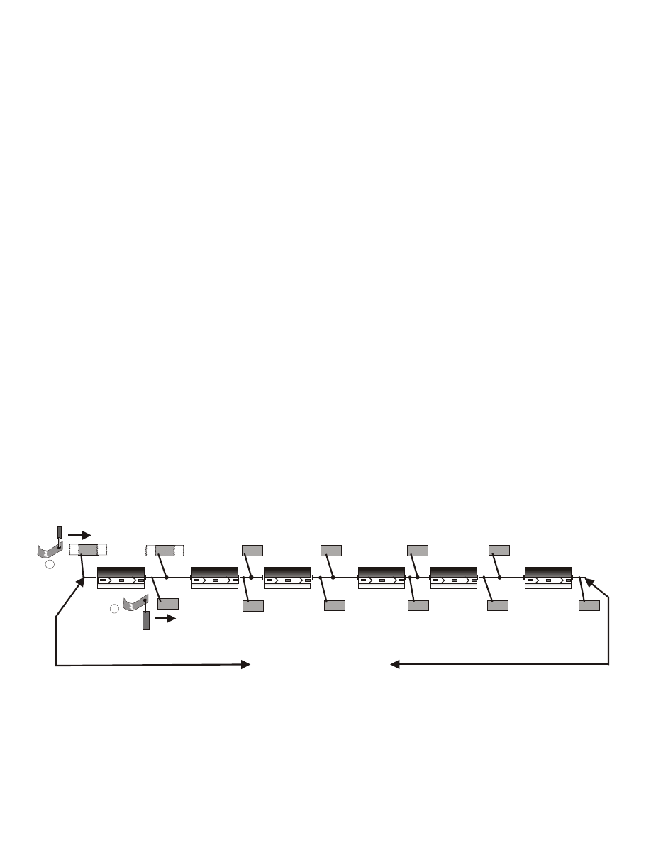
#363-a
Type III CAPACITOR INVERTER
25000 uf 50v
25000 uf 50v
+
+
_
25000 uf 50v
25000 uf 50v
+
+
_
25000 uf 50v
25000 uf 50v
+
+
_
+
+
+
+
+
+
-
-
-
-
-
-
+
_
Positive
Brush
Positive
Contacts
Negative
Contacts
Negative
Brush
A
B
144 VDC Output
To start; Instead of connecting and disconnecting capacitors in series as you may
have seen in our type II Capacitor Inverter, In this new method you simply keep all
caps connected in series as shown in figure #1. Fig. #1 is to help you get an
understanding of how it works. The positive and the negative brushes slide over the
contacts, moving together, creating a 24 VDC charge in each capacitor. For this
simple experiment you will need to connect 6 - 50 Volt x 2200 or 25,000 uf
capacitors together in series. ( solder all connections.)
Now tape down the caps flat onto a table top, Now cut 12 pieces of thick or thin (
thick is best! ) copper or aluminum to 1 1/2" x 3/4" squares and tape them down
as shown in figure #1. Now solder your wire to the contacts and the caps as shown.
Now using rubber gloves place the positive ( 16 gauge wire automotive type ) A
Brush onto the first + contact and the negative B brush on the negative contact
Now slide wires down the rows at the same time and at the same speed to charge
each capacitor at 24 VDC. Slide and charge all the way to #6 cap. So you have now
charged all caps and your DC volt meter should now read 144 VDC. ( Be careful
not to touch, it can KILL! Use rubber gloves. )
Now at this point no load is connected. Always connect load or a 120 VDC cap
bank x 25,000 uf AFTER YOU HAVE CHARGED CAPS, To avoid large sparks
that can burn up your contacts. So again after you charge 144 VDC cap bank you
then use a magnetic reed switch to turn on load.
A and B brushes move at the same time, moving all the way to the right to #6 cap and a
little past #6, and if you will picture a magnet connected to your wrist that will then switch
on the magnetic reed switch to power the load or charge your 120 VDC cap bank. Reed
switch rated at 5 to 10 amps. Now if you will picture the contacts on a round stationary
piece of plywood board and a rotor arm that turns with the brushes on it. to make contact
with the cap contacts.
TAPE
TAPE Etc....
as so.
OPTIONAL: Here is another way that you can make a high voltage inverter. Can be done
mechanically or by using SCR’s or Transistor.
Page 26
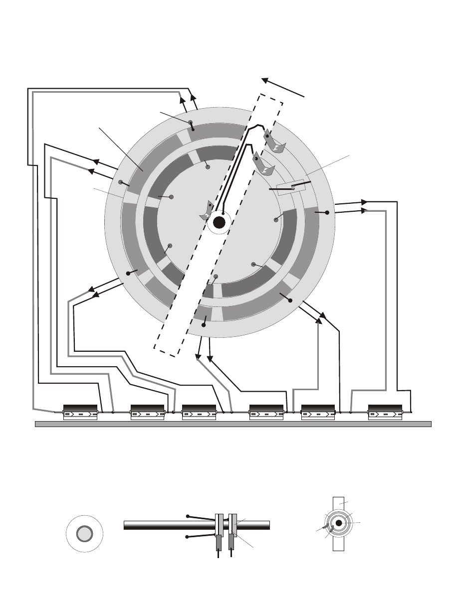
#363-a
Type III CAPACITOR INVERTER
25000 uf 50v
25000 uf 50v
+
+
_
25000 uf 50v
25000 uf 50v
+
+
_
25000 uf 50v
25000 uf 50v
+
+
_
7" disk
Space for magnetic
reed switch or switches
magnet connects to rotor that turns.
This plywood board does not turn.
+
+
+
+
+
+
_
_
_
_
_
_
#4
#7
Connect wires to caps
Epoxy Glue all + and - contacts
to plywood.
Drill holes
1
2
3
4
5
6
7
8
9
10
11
12
+
_
+
+
_
_
1.
2. 3.
4. 5.
6. 7.
8. 9.
10. 11.
12.
PENCIL MARKS
Now as #7 rotor arm moves counter clockwise, it moves the contact brushes over 1 & 2 and so on. this all happens at a
high rpm. ( You can try with lower Rpms to meet your needs.) The #4 brush is actually a set of brushes with 2 round
commutators, the same commutators you would see in a AC motor, ( Not a DC motor!) the 24 VDC from the batteries
travels through the #4 set of + and - brushes and travels through the 2 separate round commutator contacts, up through
the 2 wires, through the brushes and onto the stationary contacts. Then to the capacitors charging them at 24 VDC each
= 144 VDC. The commutator can be simple, using a 2 washer's a plastic spacer to protect from shaft, and some epoxy
glue. or place a flat type onto the moving rotor arm.
+
+
_
_
Shaft
Rotor #7 arm
+
Front View Of washer
_
_
+
+
+
_
Shaft
wood
Metal Washer Commutators
144 VDC
Below is a crude mechanical way to replace the relays if you are on a very tight budget.
Page 27
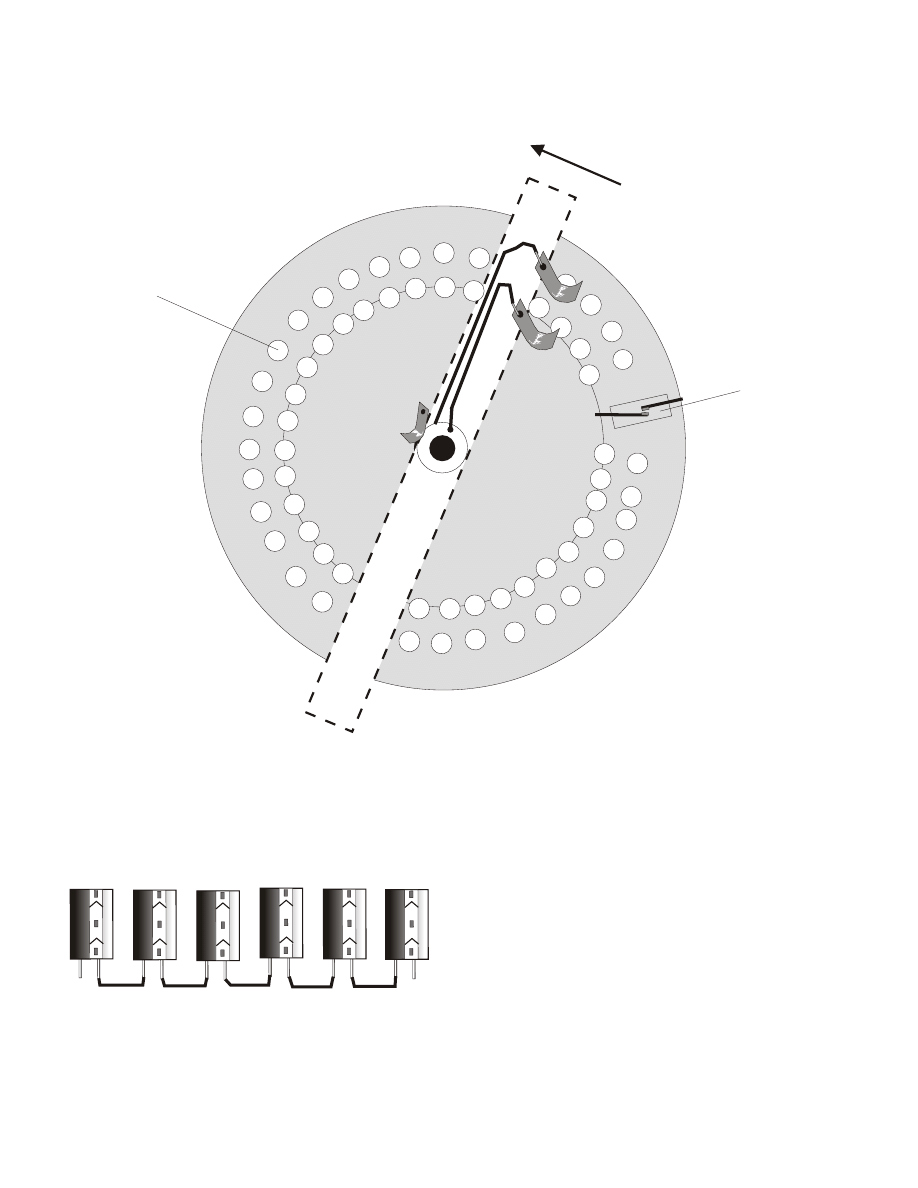
#363-A
Type III CAPACITOR INVERTER
#3
25
00
0
uf
+
25
00
0
uf
+
25
00
0
uf
+
25
00
0
uf
+
25
00
0
uf
+
25
00
0
uf
+
+
+
+
+
#4
#7
Connect wires to caps
Roofing Nails with large heads
_
4,025 VDC
DUMP CHARGE
Danger
High Voltage!
35 + nail heads = 35 200 v caps
= 4,025 VDC
65 + nail heads = 65 200 v caps
= 7,475 VDC
Use 35 to 65 of the upright caps, they are cheaper to
buy and easier to mount that many caps. Use roofing
nails with large heads and nail them into plywood
board. now sand heads and the points until shiny. now
solder all nails at points to the capacitors. see page
16. The amount of high voltage and amperage is
unlimited. this is very easy to build!
Is great for a step up High voltage source for our plans
#500, #362, #459, etc...
Output Amperage will depend on
the size of your capacitors you decide
to use. The higher the uf, the higher
the amps! High Voltage x High amps!
INPUT is 115 vdc: Use a 12 volt DC battery connected to a 500 watt INVERTER
( Which we sell if you need one.) that will step up the 12 VDC to 115 VAC 60
Hz.
Now use a 150 v volt to 200 volt Diode to change 115 VAC to DC. Or for a
greater input of 200 VDC build a Voltage doubler with caps. see our high
Caps rated at: 200-250 volts
Here is another crude mechanical way to replace the relays if you are on a very tight budget.
Page 28
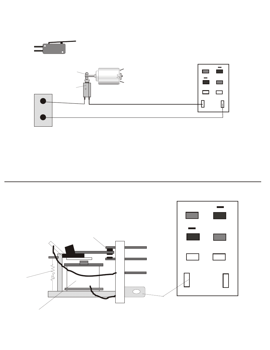
INVERTER
#363-a
+
12 VDC pulse inputs
Front View of 2pdt relay
Figure 1
+
+
12 VDC pulse inputs
Front View of 2pdt relay
+
12 VDC coil 75 ma
electromagnet
SPRING
CONTACTS
SIDE VIEW OF 4 PDT RELAY
THIS IS WHAT A RELAY LOOKS LIKE
SIDE VIEW
to 12 VDC battery
1.5 volt to 6 volt DC electric motor.
bearings or BB'S
MICRO
SWITCH
12 VDC BATTERY
MICRO SWITCH
120 vac 80 AMPS
MICRO SWITCH
120 vac 80 AMPS
SIDE VIEW of a Micro Switch
+
This is an easy way to pulse the relay to 60 Hz, ( If you do not know how to make a 60 Hz pulse electronic
generator. ) Please note that the 2pdt relay can be replaced by using 200 amp x 30 to 70 amp Transistors or
SCR's. You use them in the same way as switches. and then use a small low amp 2pdt relay to switch them
on and off. This way the SCRs or the power Transistors take all the amperage punch!
and you wont have to worry about your contacts burning out.
Page 29
Document Outline
- Page 1
- Page 2
- Page 3
- Page 4
- Page 5
- Page 6
- Page 7
- Page 8
- Page 9
- Page 10
- Page 11
- Page 12
- Page 13
- Page 14
- Page 15
- Page 16
- Page 17
- Page 18
- Page 19
- Page 20
- Page 21
- Page 22
- Page 23
- Page 24
- Page 25
- Page 26
- Page 27
- Page 28
- Page 29
- Page 30
Wyszukiwarka
Podobne podstrony:
Step Up 4
WF-II- 2-Step-up-test
step up
Step Up All In
04 Step Up
knowledge transfer in intraorganizational networks effects of network position and absortive capacit
T7 Transformacja układu odniesienia
11 BIOCHEMIA horyzontalny transfer genów
Transformacje91
5 Algorytmy wyznaczania dyskretnej transformaty Fouriera (CPS)
S up prezentacja 1 dobˇr przekroju
11Tor z transformatoramiid 13123 ppt
Transformacje2
20 H16 POST TRANSFUSION COMPLICATIONS KD 1st part PL
Immunologia Transfuzjologiczna1[1]
3 Rodzaje jednorodnych transformacji stosowanych w kinematy
Transfer sk adki US
więcej podobnych podstron