
technical manual VIP300
2
contents
1. presentation of the VIP300............................................................... 3
2. use and settings ............................................................................... 4
3. choice of sensors and operating ranges .......................................... 9
4. connection scheme .......................................................................... 10
5. assembly .......................................................................................... 11
6. IDMT tripping curves ........................................................................ 13
7. technical characteristics ................................................................... 17
8. testing of the VIP300 and use of the VAP6 ...................................... 20
technical manual VIP300
3
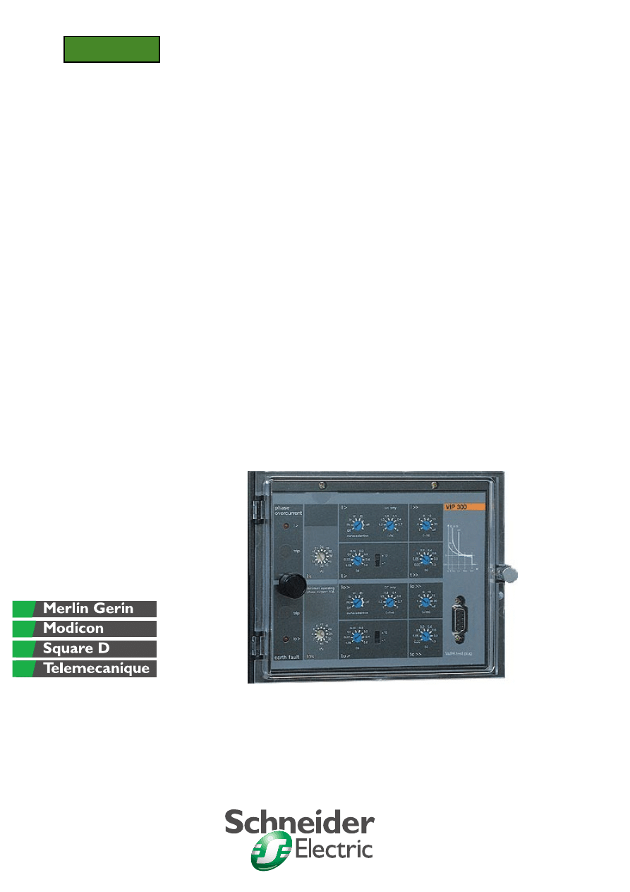
1. presentation of the VIP300
VIP300
Mitop
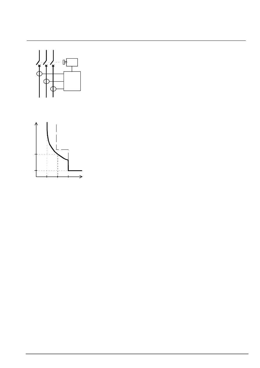
- simplified wiring scheme -
10Is
t>
I>>
t>>
- phase or earth fault curves -
1,2Is
I
t
self-powered protective relay
n
The VIP300 relay is designed for
use in distribution networks. It may be
used as MV/LV transformer
protection, protection at the incoming
point of industrial installations, and
also as branch feeder protection.
n
The VIP300 provides protection
against phase-to-phase faults and
earth faults. The choice of tripping
curves and the multiple settings allow
it to be used in a wide variety of
discrimination plans.
The VIP300 is a self-powered relay,
energized by the current sensors; it
does not require any auxiliary source.
It actuates a Mitop release.
phase protection
The phase protection has two
separately adjustable settings:
n
the low setting may be chosen with
definite time or IDMT. The IDMT
curves are in compliance with the IEC
255-3 standard. They are of the
standard inverse, very inverse and
extremely inverse types.
The low setting may also be used
with the RI curve.
n
the high setting is of the definite
time type.
earth protection
The earth fault protection operates by
residual current measurement: it uses
the sum of the sensor secondary
currents.
Like phase protection, earth
protection has two separately
adjustable settings.
LL and LH models
There are two models of the VIP300:
VIP300LL and VIP300LH, They differ
with respect to :
n
operating range.
Refer to the chapter entitled "choice
of sensors and operating ranges".
n
the VIP300LH has a table for
setting "equivalent time multiplier"
conversion on the front.
sensors
In order for the specified
performances to be obtained, the
VIP300 relay must be used with the
following current transformers:
n
CRa and CRb sensors:
(for RM6s 1998 and later).
n
CSa and CSb sensors of the SFset
circuit breaker. The CSa and CSb
sensors have the same number of
secondary turns as the CRa and CRb
sensors respectively.
n
200/1 and 800/1 sensors of the
Ringmaster:
description
n
The VIP300 relay is mounted in a
polycarbonate injected casing which
protects it against dripping water and
dusty environments.
The front is protected by a
transparent cover fitted with a sealing
joint. The cover may be lead-sealed
to prohibit access to the settings.
n
Rotating selector switches are
used for setting. The phase setting
current and earth fault setting current
are set in amperes. This means that
the scale on the front must be
adapted to suit the sensor used. This
is done by positioning a "setting scale
label" on the relay at the time of
assembly.
n
Connections are made on the back
using fast-on clips.
indication
Two indicators indicate the origin of
tripping (phase or earth). They stay in
position after a break in the relay
power supply.
Two LEDs (phase and earth) indicate
that the low setting has been overrun
and that the time delay is running.
technical manual VIP300
4
2. use and settings
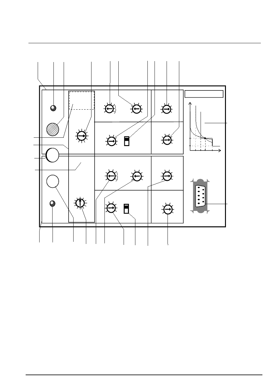
front view
I>>
(sec)
0.03
0.05
0.1
0.2
0,4
0,6
0,9
1.5
(x Ios)
t>>
t>
(sec)
0.1
0.05
0.6
0.15 0.2
0.3
0.4
0.07
x 1
x 10
I>
overcurrent
phase
curve selection
curve selection
Is
I>
Ios
Io>
to
>
(sec)
to
>>
VIP300LL range: x 1
sensors:
earth fault
Io>
reset
trip
trip
minimum operating
phase current
:
10A
(A)
10
12
15
18
21 24 28
32
36
40
45
50
30
35
40
16
1
2
4
8 12
20
25
6
(A)
DT only
(x Is)
3
1
1.2
1.8
2.4
2.7
2.1
1.5
DT only
(x Ios)
DT
SI
VI EI
RI
off
(x Is)
3
4
6
9
12
15
20
off
x 1
x 10
VIP 300
1.2Is
10Is
t>
I>>
t>>
EI, VI, SI
I>
RI
DT
Is
Io>>
DT
SI
VI EI
RI
off
3
1
1.2
1.8
2.4
2.7
2.1
1.5
3
4
6
9
12
15
20
off
0.03
0.05
0.1
0.2
0,4
0,6
0,9
1.5
(sec)
0.07
0.05
0.1
0.15 0.2
0.3
0.4
0.6
VAP6 test plug
1
2
3
4
5
6
7 8
9
10
b
a
c
11
12
13
14 15 16
17
18
19
20
e
d
CRa 51007003F0
- front panel -
f
phase protection
earth protection
other functions
1. phase setting zone
2. setting overrun indicator
3. phase trip indicator
4. phase setting current Is
5. choice of low setting curve type
6. low setting I>
7. low setting time delay t>
8. multiplying factor (low setting)
9. high setting I>>
10. high setting time delay t>>
11. earth setting zone
12. setting overrun indicator
13. earth trip indicator
14. earth setting current Ios
15. choice of low setting curve type
16. low setting Io>
17. low setting time delay to>
18. multiplying factor (low setting)
19. high setting Io>>
20. high setting time delay to>>
a. setting scale label
b. sensor and range information
c. indicator reset
d. minimum operating current
e. VAP6 test plug
f. VIP300LL: tripping curves
VIP300LH: table for « equivalent
time multiplier » conversion.
technical manual VIP300
5
2. use and settings (cont’d)
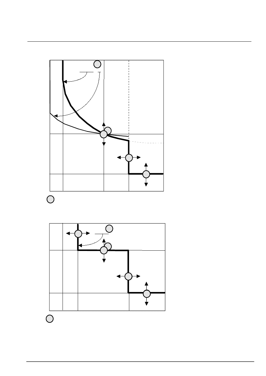
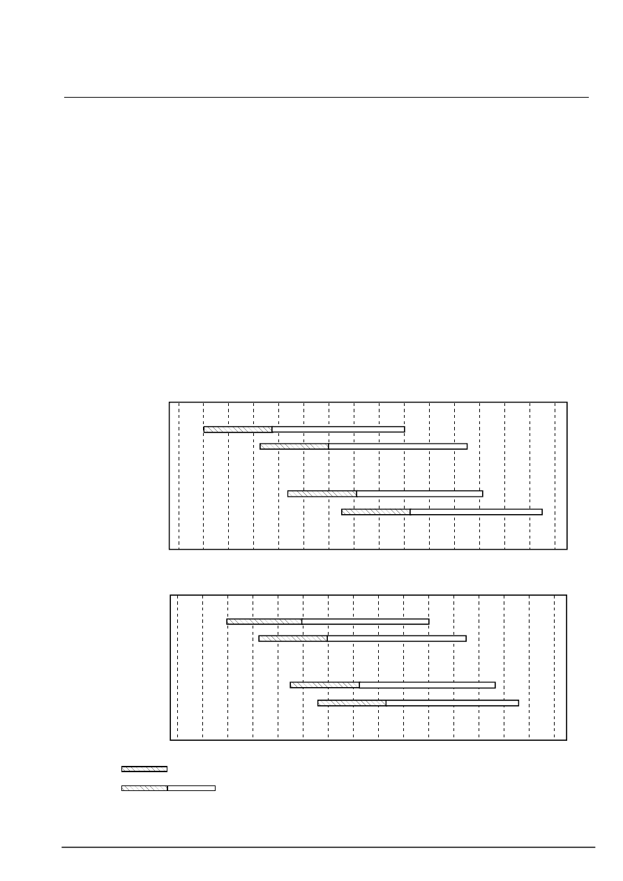
tripping curves
1,2 Is
10 Is
t>>
t>
I>>
SI, VI, EI, RI
low setting
4
10
9
5
8
7
Is
fig 1: phase setting : IDMT low threshold
1,2 Is
I>
t>>
t>
I>>
fig 2: phase setting: definite time low threshold
DT
low setting
5
6
9
10
4
8
7
Is
settings
phase protection setting
The numbers indicated on the curves
opposite are those of the phase
protection setting switches (refer to
the diagram of the front view).
Set:
n
setting current Is (4)
n
type of low setting I> curve (5)
IDMT: RI, SI, VI, EI
definite time: DT
n
low setting I> (6)
This setting is only active if the low
setting curve chosen is of the definite
time DT type (fig 2). For the other
choices, SI, VI, EI, RI (fig 1), the
selector switch is disabled.
n
low setting time delay t> (7) and (8)
n
high setting I>> (9)
n
high setting time delay t>> (10)
earth protection setting
The principle is the same as for
phase protection.
Set:
n
setting current Ios (14)
n
type of low setting Io> curve (15)
IDMT: RI, SI, VI, EI
definite time: DT
n
low setting Io> (16)
This setting is only active if the low
setting curve chosen is of the definite
time DT type. For the other choices,
SI, VI, EI, RI, the selector switch is
disabled.
n
low setting time delay to> (17) and
(18)
n
high setting Io>> (19)
n
high setting time delay to>> (20)
operation
The high and low settings operate
separately. The tripping order results
from the "logical OR" between the
two settings.

technical manual VIP300
6
2. use and settings (cont’d)
phase protection
1. phase protection setting
zone
All the information concerning phase
protection is grouped together in the
dark zone of the upper half of the
front face.
2. setting overrun indicator
When the red indicator blinks, it
means that the phase protection low
setting time delay is running. When
this is the case, if the current does
not decrease, the relay will trip.
n
for IDMT curves (SI, VI, EI), the
LED lights up when the current is
greater than 1.2 times the setting
current Is.
n
for the IDMT curve (RI), it lights up
when the current is greater than the
Is setting.
n
for the definite time curve DT, it
lights up when the low setting is
overrun.
F
also refer to "indicator reset
button".
3. trip indicator
It is normally black and turns yellow
to indicate that the phase protection
has given a tripping order. It stays in
the same status, even when the relay
is no longer energized.
4. choice of setting current Is
The setting current setting range
depends on the sensor and range
used: the selector switch scale
should be adapted to suit the sensor
and range using the setting scale
label.
F
also refer to "choice of sensors
and operating ranges" chapter.
5. choice of type of low setting
curve
DT: definite time
SI: inverse time
VI: very inverse time
EI: extremely inverse time
RI: specific curve
off: low setting is disabled.
6. choice of low setting I>
The setting is a multiple of the setting
current. It is only active for definite
time settings (selector switch 5 set to
DT).
If the tripping curve is selected with
IDMT (selector switch 5 set to RI, SI,
VI, EI), the selector switch has no
effect.
7. setting of low setting time
delay t>.
n
If the tripping curve is of the
definite time (DT) type, the selector
switch sets the low setting time delay.
n
If the curve is of the IDMT type (RI,
SI, VI, EI), the value displayed is the
tripping time for a phase current
equal to 10 times the setting current.
8. low setting time delay
multiplying factor.
In the x10 position, the time delay
displayed on selector switch 7 is
multiplied by 10.
9. setting of high setting I>>.
The high setting is chosen as a
multiple of the setting current.
In the "off" position, the high setting is
disabled.
10. setting of high setting time
delay t>>.
The time delay is set directly in
seconds.

technical manual VIP300
7
2. use and settings (cont’d)
earth protection
The setting principle is the same as
for phase protection.
11. earth protection setting
zone
The earth protection settings are
grouped together in the dark zone of
the lower half of the front face.
12. setting overrun indicator
When this indicator blinks, it means
that the earth protection low setting
time delay is running. When this is
the case, if the current does not
decrease, the relay will trip.
n
for IDMT curves (SI, VI, EI), the
LED lights up when the current is
greater than 1.2 times the setting
current Ios.
n
for the IDMT curve (RI), it lights up
when the current is greater than the
Ios setting.
n
for the definite time curve DT, it
lights up when the low setting is
overrun.
F
for the cases above, the LED only
lights up when a phase current is
greater than the minimum operating
current.
F
also refer to "indicator reset
button".
13. trip indicator
It is normally black and turns yellow
to indicate that the phase protection
has given a tripping order. It stays in
the same status, even when the relay
is no longer energized.
14. choice of setting current Ios
This is the maximum residual current
that can flow in the network without
the protection being triggered.
The Ios current setting range
depends on the sensor and range
used: the selector switch scale
should be adapted to suit the sensor
and range using the setting scale
label.
F
also refer to "choice of sensors
and operating ranges" chapter.
15. choice of type of low setting
curve
DT: definite time
SI: inverse time
VI: very inverse time
EI: extremely inverse time
RI: specific curve
off: low setting is disabled.
16. choice of low setting Io>
The setting is a multiple of the setting
current. It is only active for definite
time settings (selector switch 15 set
to DT).
If the tripping curve is selected with
IDMT (selector switch 15 set to RI, SI,
VI, EI), the selector switch has no
effect.
17. setting of low setting time
delay to>.
n
If the tripping curve is of the
definite time (DT) type, the selector
switch sets the low setting time delay
n
If the curve is of the IDMT type (RI,
SI, VI, EI), the value displayed is the
tripping time for an earth current
equal to 10 times the setting current.
18. low setting time delay
multiplying factor.
In the x10 position, the time delay
displayed on selector switch 17 is
multiplied by 10.
9. setting of high setting Io>>.
The high setting is chosen as a
multiple of the setting current Ios.
In the "off" position, the high setting is
disabled.
10. setting of high setting time
delay t>>.
The time delay is set directly in
seconds.
technical manual VIP300
8
2. use and settings (cont’d)
other functions
CRb 51007004F0
VIP300LL range: x 1
Is
Ios
(A)
6.2
12.5
25
37
50 75
187
218
156
100
125
250
62
75
94
112
131 150 175
200
225
250
281
312
(A)
recto
minimum operating
phase current : 62A
CRb 51007004F0
VIP300LL range: x 4
Is
Ios
(A)
25
50
100
200 300 400
150
875
1000
750
625
500
250
300
375
450
525 600 700
800
900
1000
1125
1250
(A)
verso
minimum operating
phase current:250A
- setting scale label -
sensors:
sensors:
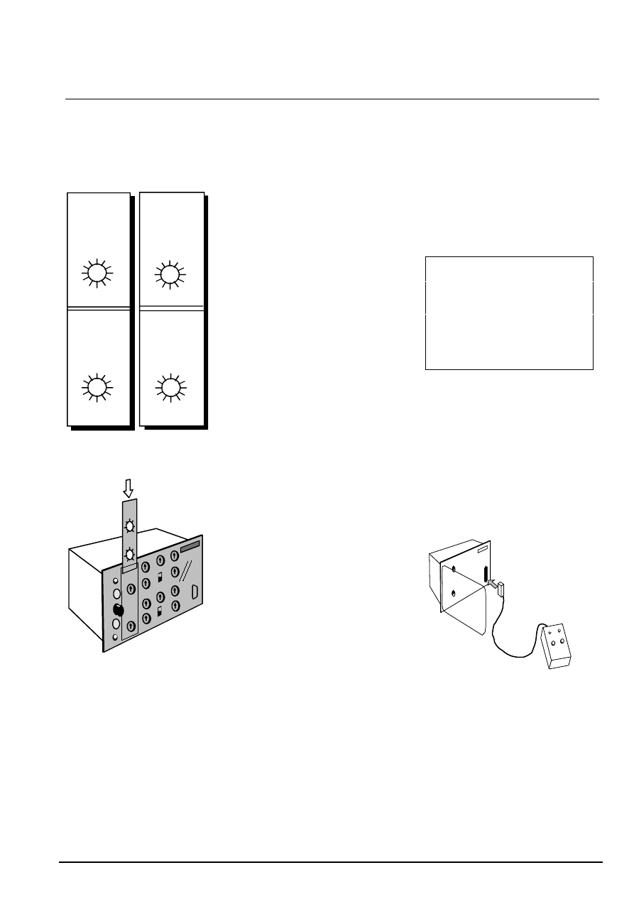
- how to install the setting scale label -
a. setting scale label
n
it should be mounted on the
VIP300 when it is assembled on the
circuit breaker. The label indicates
the scales for the phase setting
current and earth protection setting
current. It is inserted, from the top,
behind the transparent part of the
front face.
n
each VIP300 comes with a set of
labels. Install the label that matches:
- the type of sensor used
- the VIP300 model
- the range used
n
each setting scale label matches a
sensor and is printed on both sides
for each of the 2 ranges. The label
may therefore be turned around if the
VIP300 range is changed during the
service life of the installation.
F
also refer to "assembly" chapter.
b. sensor and range indication
The text is printed on the setting
scale label.
When the label is installed in the slot,
the text is hidden by an opaque zone.
It is not visible to the user.
c. indicator reset button
The button is accessible when the
transparent cover is closed. When
the button is pressed, 2 actions are
triggered:
n
it resets (black position) the 2
phase and earth trip indicators. When
the relay is no longer energized, it is
still possible to reset the indicators for
about 48 hours. After that time, they
may be reset after the VAP6 is
plugged in.
n
it triggers the lighting up of the 2
red LEDs (about 3 sec). This
indicates that:
- the relay is energized. The indicator
lights up when the current is greater
than the minimum operating current.
- relay self-testing results are OK.
If one of the two conditions is not
met, the indicators do not light up.
This function may be used to carry
out a basic relay operation test.
d. minimum operating current
The minimum operating current is the
phase current required for the relay to
be energized and operational. It is
printed on each setting scale label.
The value given on the setting scale
label is the single-phase rms
minimum operating current.
The minimum operating current is
always the lowest setting current
setting.
F
note regarding minimum
operating current:
The VIP300 does not operate below
the minimum operating current level.
As a result, if the earth protections
are set below the minimum operating
current, they will only take effect
when there is phase current greater
than or equal to the minimum
operating current.
e. VAP6 test plug
The test plug is exclusively designed
for connection of the VAP6 which is
used for fast, simplified relay testing.
The operation may be carried out
while the relay is operating since the
VAP6 and VIP300 provide the
possibility of testing with inhibition of
circuit breaker tripping.
F
also refer to the "testing of the
VIP300 and use of the VAP6"
chapter.
- testing of the VIP300 using the VAP6 -
technical manual VIP300
9
3. choice of sensors and operating ranges
selection principle
Choose the sensor to be used and
the VIP300 connection range in
accordance with the desired
operating range. Refer to the charts
below.
sensors
The VIP300 should be used with the
specified sensors. The relay/sensor
assembly must be used together in
order to comply with the
characteristics, in particular:
- operation across the range
- response time
- accuracy
- short-circuit current behaviour
It is compulsory for the 3 sensors to
be of the same type.
sensors specified for VIP300LL:
- CRa 200/1 51007003F0 (1)
- CRb 1250/1 51007004F0 (1)
sensors specified for
VIP300LH:
- Ringmaster 200/1 4509996A0
- Ringmaster 800/1 4509169A0
(1): for RM6 model 98 and higher.
range
The VIP300 relay contains input
transformers that have an
intermediary tap on the primary
winding. Each tap corresponds to a
rating with a different operating range.
VIP300LL model ranges:
- X1
- X4
VIP300LH model ranges:
- X2
- X4
VIP300LL model operating ranges
CRa
CRb
10
20K
100
1k
10k
20
30
60
200
300
600
2k
3k
6k
4k
50
40
62,5
312
6,25K
25K
250
1,25K
range x1
range x4
range x4
range x1
10
200
1k
Amps
VIP300LH model operating ranges
Ringmaster 200/1
Ringmaster 800/1
10
20K
100
1k
10k
20
30
60
200
300
600
2k
3k
6k
4k
40
80
400
8K
16K
160
800
range x2
range x4
range x4
range x2
200
100
20
2k
Amps
operating current Is setting range
selective operating range
For a given operating range, the
bottom of the setting current range
represents the relay minimum
operating current.
technical manual VIP300
10
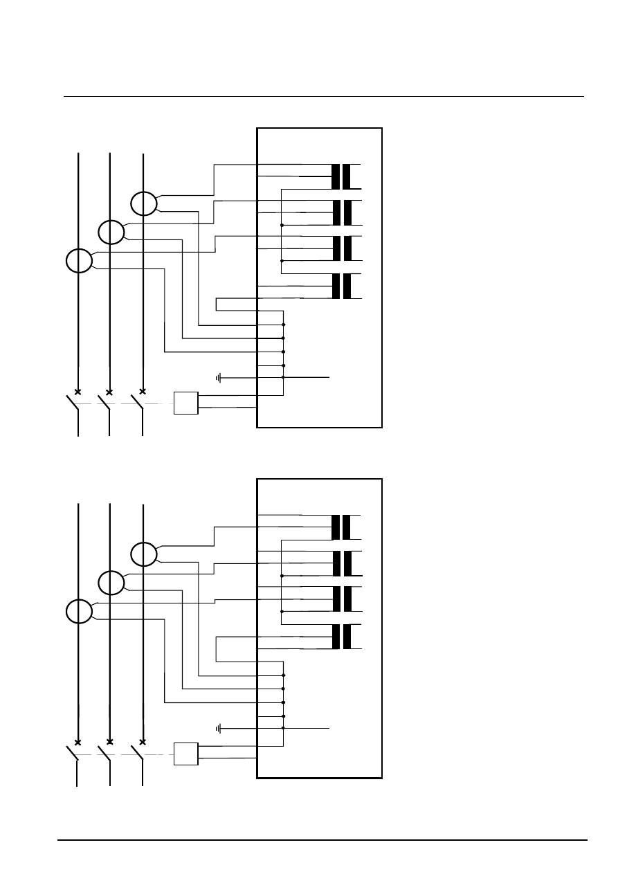
4. connection scheme
wiring to x1 (or x2) range
VIP300LL
S1
S2
S1
S2
S1
S2
x 4
x 4
x 4
x 4
P1
P2
P1
P2
P1
P2
1
2
3
3
4
5
6
7
8
9
1
2
(VIP300LH)
x 1
(x2)
x 1
(x2)
x 1
(x2)
x 1
(x2)
L3
L2
L1
Io
MITOP
+
-
15
16
10
11
12
13
14
0 V
wiring to x4 range
VIP300LL
S1
S2
S1
S2
S1
S2
x 4
x 4
x 4
x 4
P1
P2
P1
P2
P1
P2
1
2
3
3
4
5
6
7
8
9
1
2
(VIP300LH)
x 1
(x2)
x 1
(x2)
x 1
(x2)
x 1
(x2)
L3
L2
L1
Io
MITOP
+
-
15
16
10
11
12
13
14
0 V
The connection is made on the back
of the VIP300
connection using fast-on clips
The standard way to connect the
VIP300 is by means of 6.35 mm fast-
on clips.
technical manual VIP300
11
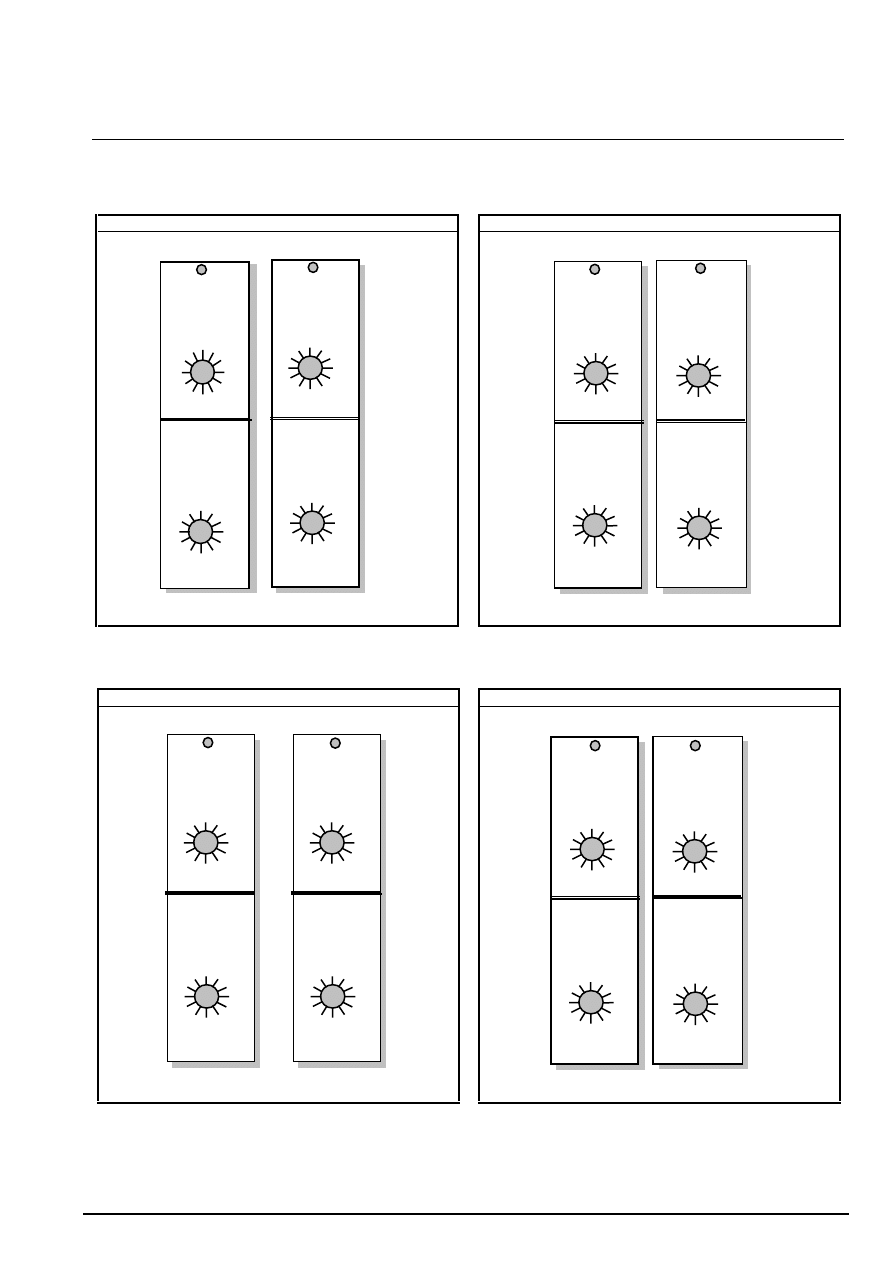
5. assembly
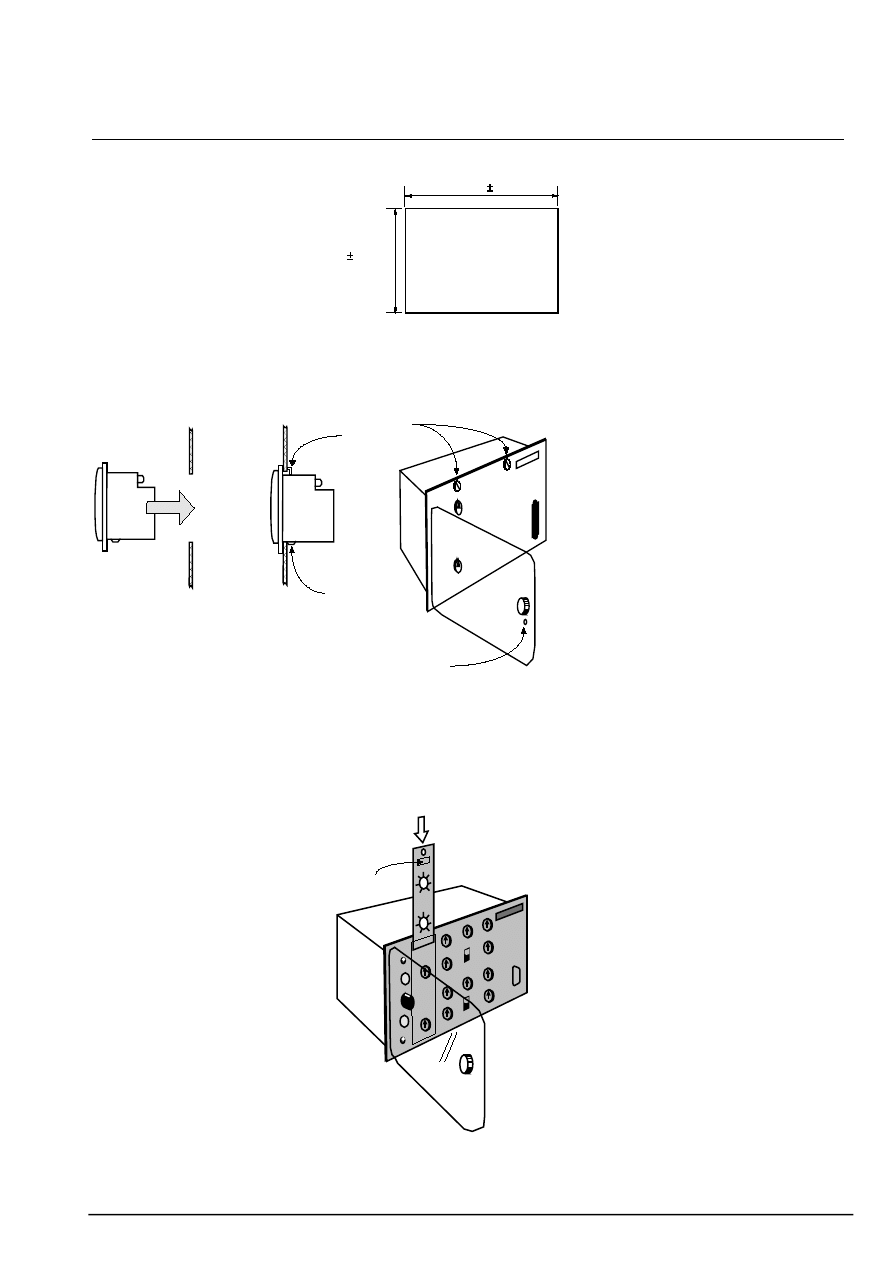
cut-out
161 0.5mm
130 0.5mm
- drilling of cut-out -
The VIP300 is flush-mounted in a
rectangular cut-out made in a metal
plate 3 mm thick at the most.
assembly
E
V
N
P
n
insert the VIP300 in the cut-out and
correctly position the 2 lower pins (E)
of the casing on the edge of the
metal plate cut-out.
n
tighten the screws (V) on the 2
mounting lugs accessible via the front
face after having opened the
transparent cover.
n
after tightening, make sure that the
latch (N) of each lock (visible on the
rear face) is in the vertical position,
pressing against the support plate.
F
the latch may be put into the
vertical position by loosening each of
the screws (V) before tightening
them.
n
the hole (P) may be used to lead-
seal the relay after the setting scale
label is installed and the settings are
made.
installation of the setting scale label
M
n
slide the setting scale label into
position behind the transparent part
of the front face.
F
refer to the section entitled
"choice of the setting scale label".
n
make sure that the information
given at the top of the label (M)
matches:
the sensor used (sensor)
the VIP300 model
the range used (range)
This information is hidden when the
label is in position.
n
make sure that it is pushed right to
the bottom of the slot.
n
to remove the label, use the hole in
the top, if necessary with the help of
the tip of a pencil or a screwdriver.
technical manual VIP300
12
5. assembly (cont’d)
choice of the setting scale label
for VIP 300 LL with CRa sensors
for VIP 300 LL with CRb sensors
Is
Ios
minimum operating
phase current : 10A
10
12
15
18
21 24 28
32
36
40
45
50
(A)
30
35
40
16
1
2
4
8
12
20
25
6
(A)
VIP300LL range: x 1
sensors:
CRa 51007003F0
recto
sensor:
VIP300LL range: x 4
Is
Ios
4
8
16
24
32 48 64
80
160
140
120
100
(A)
72
84 96 112
128
144
160
180
200
40
48
60
(A)
minimum operating
phase current :40A
verso
CRa 51007003F0
x 1 range x 4 range
Is
Ios
(A)
6.3
12.5
25
37
50 75
187
218
156
100
125
250
63
75
94
112
131 150 175
200
225
250
281
312
(A)
recto
minimum operating
phase current : 63A
Is
Ios
25
50
100
200
300 400
150
875
1000
750
625
500
(A)
250
300
375
450
525 600 700
800
900
1000
1125
1250
(A)
verso
minimum operating
phase current:250A
sensor:
VIP300LL range: x 1
CRb 51007004F0
sensor:
VIP300LL range: x 4
CRb 51007004F0
x 1 range x 4 range
for VIP 300 LH with 200/1 RMR sensors
for VIP 300 LH with 800/1 RMR sensors
Is
Ios
4
8
16
24
32 48 64
80
160
140
120
100
(A)
72
84 96 112
128
144
160
180
200
40
48
60
(A)
minimum operating
phase current : 40A
verso
sensor:
VIP300LH range: x 4
200/1: 4509996A0
Is
Ios
2
4
8
12
16 24 32
40
80 70
60
50
(A)
36
42 48 56
64
72
80
90
100
20
24
30
(A)
minimum operating
phase current : 20A
recto
sensor:
VIP300LH range: x 2
200/1: 4509996A0
x 2 range x 4 range
Is
Ios
(A)
8
16
32
48
64 96
240
280
200
128
160
320
80
96
120
144
168 192 224
256
288
320
360
400
(A)
minimum operating
phase current : 80A
sensor:
VIP300LH range: x 2
800/1 4509169A0
Is
Ios
16
32
64
128
192 256
96
560
640
480
400
320
(A)
160
192
240
288
336
384
448
512
576
640
720
800
(A)
minimum operating
phase current:160A
sensor:
VIP300LH range: x 4
800/1 4509169A0
verso
recto
x 2 range x 4 range
technical manual VIP300
13
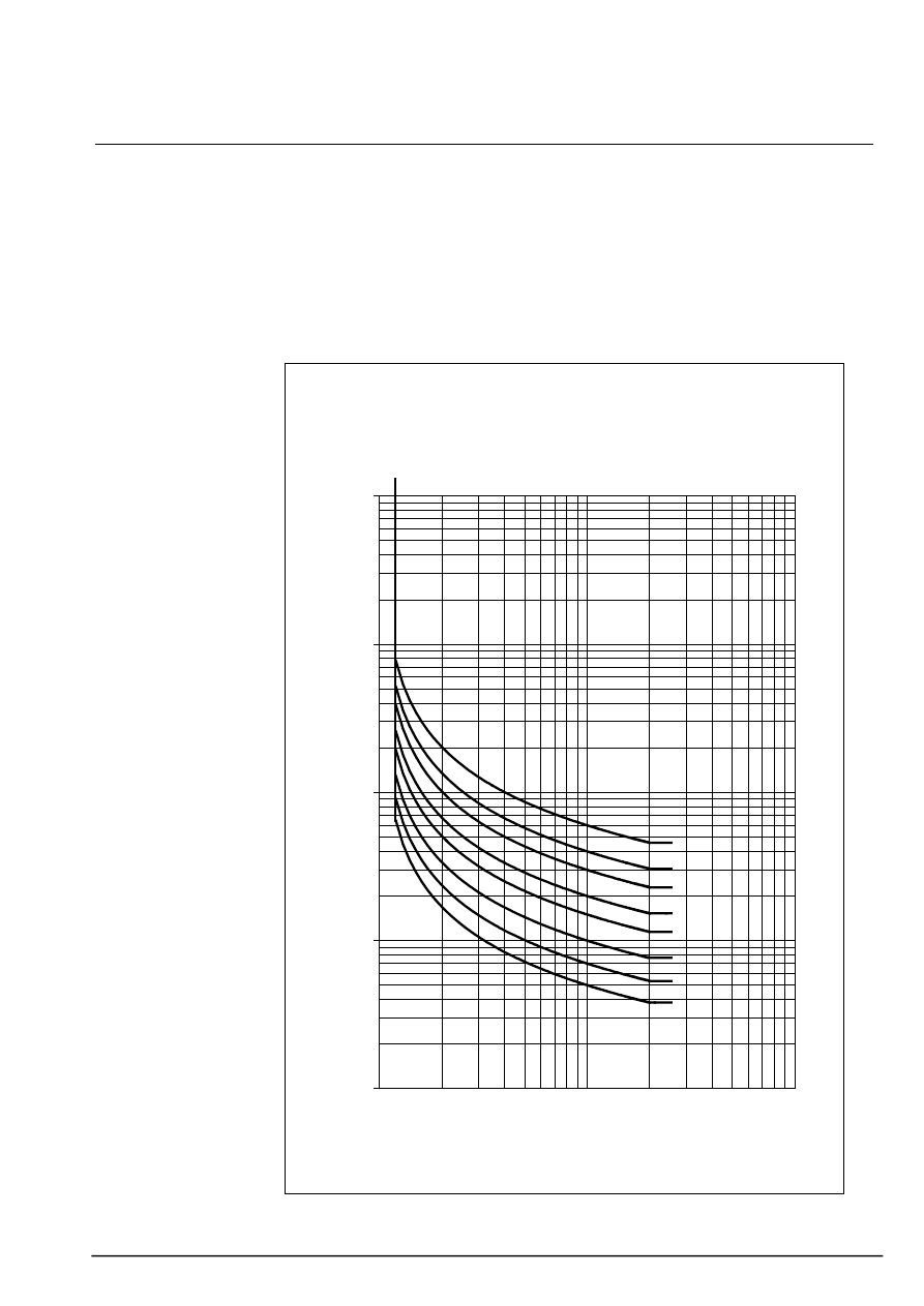
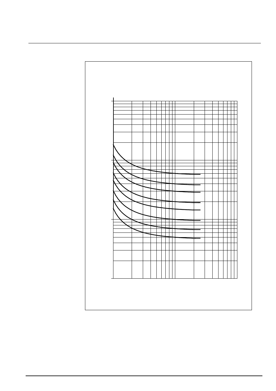
6. IDMT tripping curves
n
the curves in this chapter indicate
the IDMT low setting tripping times for
the 16 time delay t> (or to>) settings.
n
the phase protection and earth
protection curves are the same.
n
the numbers given on the right of
the curves represent the position of
the time delay t> (or to>) selector
switch.
(if the multiplying factor x1 / x10 is in
the x10 position, multiply the times
indicated by 10).
SI curve
SI
I/Is
t (s
)
0.01
0.1
1
10
100
1
10
100
0,05
0,07
0,1
0,15
0,2
0,3
0,4
0,6
1,2 Is
technical manual VIP300
14
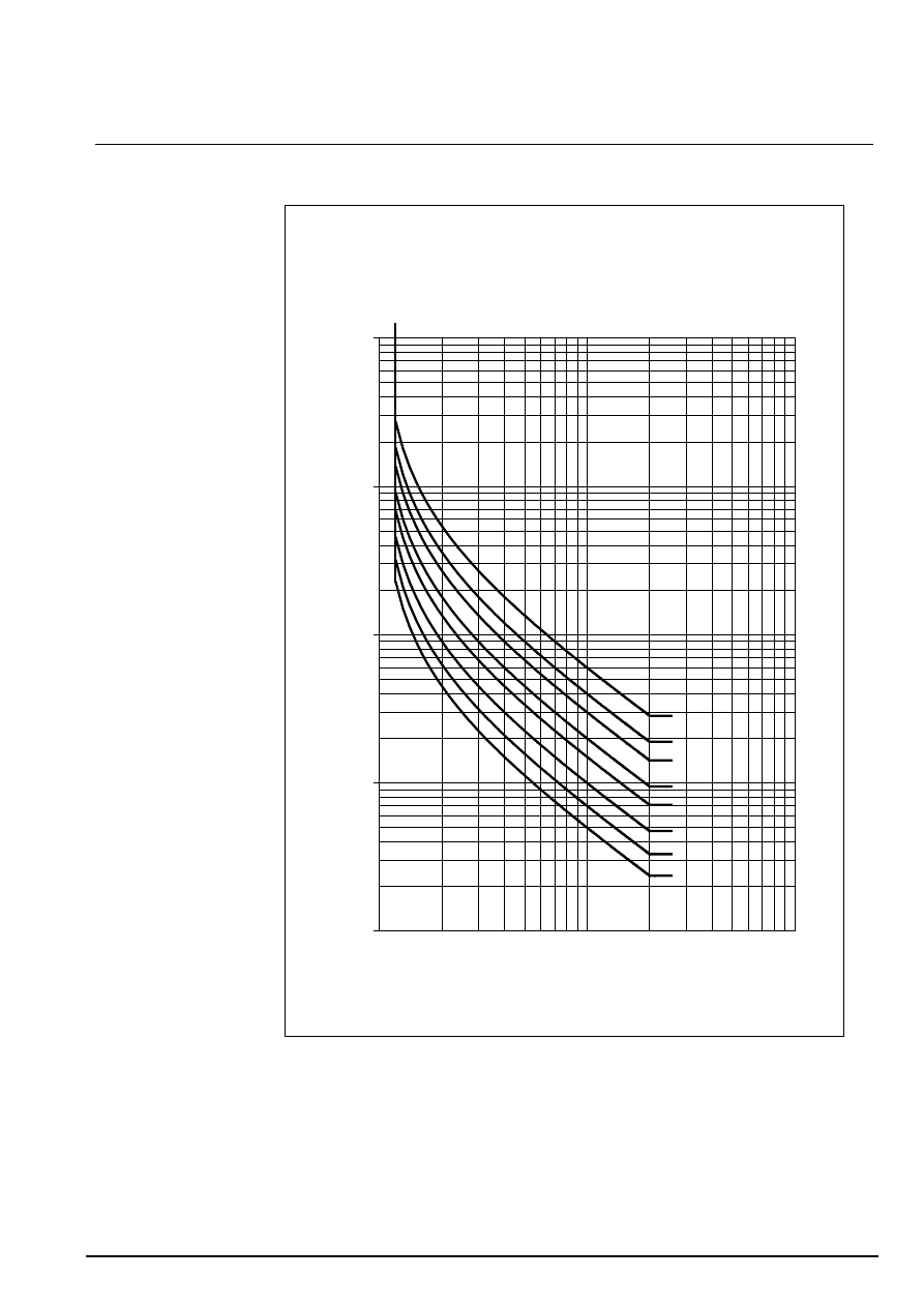
6. tripping curves (cont’d)
VI curve
VI
I/Is
t (s
)
0.01
0.1
1
10
100
1
10
100
0,05
0,07
0,1
0,15
0,2
0,3
0,4
0,6
1,2 Is
technical manual VIP300
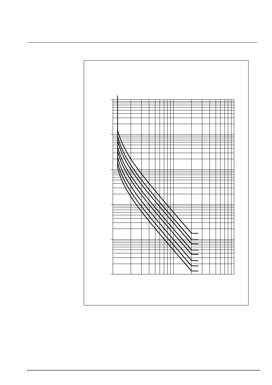
15
6. tripping curves (cont’d)
EI curve
EI
I/Is
t (s
)
0.01
0.1
1
10
100
1000
1
10
100
0,05
0,07
0,1
0,15
0,2
0,3
0,4
0,6
1,2 Is
technical manual VIP300
16
6. tripping curves (cont’d)
RI curve
RI
I/Is
t (s
)
0.01
0.1
1
10
1
10
100
0,05
0,07
0,1
0,15
0,2
0,3
0,4
0,6

technical manual VIP300
17
7. technical characteristics
phase protection
accuracy
see notes
low setting I>
±
5% or 0/+2A
1
low setting time delay t>
definite time
IDMT
±
2% or
±
20 ms
class 5 according to IEC 60255-3 or
0/+20ms
2, 8
2, 8
high setting I>>
±
5%
high setting time delay t>>
±
2% or
±
20 ms
2
% of pick-up
95%
storage time
20 ms
earth protection
accuracy
see notes
low setting Io>
±
5% or 0/+2A
3, 4, 5
low setting time delay to>
definite time
IDMT
±
2% or
±
20 ms
class 5 according to IEC 60255-3 or
0/+25ms
2, 8
2, 5, 8
high setting Io>>
±
5%
high setting time delay to>>
±
2% or
±
20 ms
2, 8
% of pick-up
95%
storage time
20 ms
general characteristics
value
steady thermal resistance
240 A
1500 A
240 A
960 A
with CRa sensor
with CRb sensor
with RMR 200/1 sensor
with RMR 800/1 sensor
1 sec thermal resistance
25 kA/1s
25 kA/1s
20 kA/1s
with CRa, CRb, RMR800/1
sensors
with RMR200/1 sensor on
range x2
with RMR200/1 sensor on
range x4
operating frequency
50 Hz
±
10%, 60 Hz
±
10%
operating temperature
-25° C to +70° C
storage temperature
-40°C to +85°C
weight
1.7 kg
minimum operating current
range
value
see notes
VIP300LL + CRa sensor
x1
10A
7
x4
40A
VIP300LL + CRb sensor
x1
62A
x4
250A
VIP300LH + RMR 200/1 sensor
x1
20A
x2
40A
VIP300LH + RMR 800/1 sensor
x1
80A
x2
160A
climatic resistance
standard
severity
low temperature operation
IEC 60068-2-1
-25°C, 16h
low temperature storage
IEC 60068-2-1
-40°C, 96h
high temperature operation
IEC 60068-2-2
+70°C, 16h
high temperature storage
IEC 60068-2-2
+85°C, 96h
fast changes in temperature
IEC 60068-2-14
-25°C to +70°C, 5 cycles
operation in damp heat
IEC 60068-2-3
56 days, 93% RH
salt spray
IEC 60068-2-52
severity 1
mechanical resistance
standard
severity
vibrations
IEC 60255-21-1
class 2
shocks and jolts
IEC 60255-21-2
class 2
earthquakes
IEC 60255-21-3
class 2
enclosure protection index
EN 60529
IP54, (cover closed)
fire resistance
IEC 60695-2-1
650°C

technical manual VIP300
18
7. technical characteristics (cont’d)
electrical resistance
standard
severity
sensor input isolation
IEC 60255-5
2 kV rms, 50 Hz, 1 mn
1.2/50 µs impulse voltage
IEC 60255-5
5 kV, note 6
1 MHz dampened oscillating wave
IEC 60255-22-1
2,5 kV cm, note 6
1 kV dm
rapid transient bursts
IEC 60255-22-4
4 kV cm and dm, 5 kHz burst, note 6
1.2/50(8-20 µs) hybrid wave
IEC 61000-4-5
2 kV, 42 ohms, note 6
electrostatic discharge
IEC 60255-22-2
8 kV in air, 6 kV on contact
HF electromagnetic field
IEC 60255-22-3
30V/m not modulated, 27 to 1000 MHz
EN 50082-2
10 V/m mod. ampl., 80 to 1000 MHz
EN 50082-2
10 V/m mod.impuls., 900 MHz
notes
1. Value given for three-phase
VIP300 power supply.
For single-phase operation, the
accuracy range is
±
10% or 0/+4A.
For the low setting, this does not
generally represent a real operating
situation. However, it may occur
during injection testing carried out
with single-phase.
The error is mainly due to the non-
linearity of the sensors and VIP300
input transformers with weak current,
the inaccuracy being accentuated
when the relay is only supplied by
one phase.
2. The accuracy is indicated for a
fault that occurs when the VIP300 is
already supplied by the current let
through by the circuit breaker. The
accuracy is indicated for sinusoidal
current. In the event of closing while
a fault is present, the tripping time
may be extended by:
+30 ms at 1.5 Is
+20 ms from 2 Is to 10 Is
+10 ms above 10 Is
3. Generally speaking, the accuracy
ranges of earth protection times and
settings are indicated for when the
VIP300 is supplied by current that is
greater than or equal to the minimum
operating current. The measurement
of a setting for earth protection with
single-phase supply is therefore not
significant if the setting is lower than
the minimum operating current.
4. Value given for three-phase
VIP300 supply. For single-phase
testing, the accuracy is
±
10% or
0/+4A. For the low setting, this may
occur when the earth protection is
tested with single-phase supply, and
no supply by the other phases.
5. In the following specific conditions:
- VIP300LL
- with CRa sensor
- wiring to x1 range
- if Ios < 8A
- if phase current < 20A
the setting and time delay
characteristics are:
- low settings:
±
10% 0/+4A
- class not specified
6. Not applicable to test plug
7. Accuracy
±
10% or
±
1.5A.
The value indicates the guaranteed
minimum operating current for single-
phase operation. With three-phase
oepration, it may be less than the
value indicated.
8. The tripping times indicated do not
include the mitop response time. Its
tripping time depends on its
mechanical load (for no load, its
tripping time is less than 5 ms)
technical manual VIP300
19
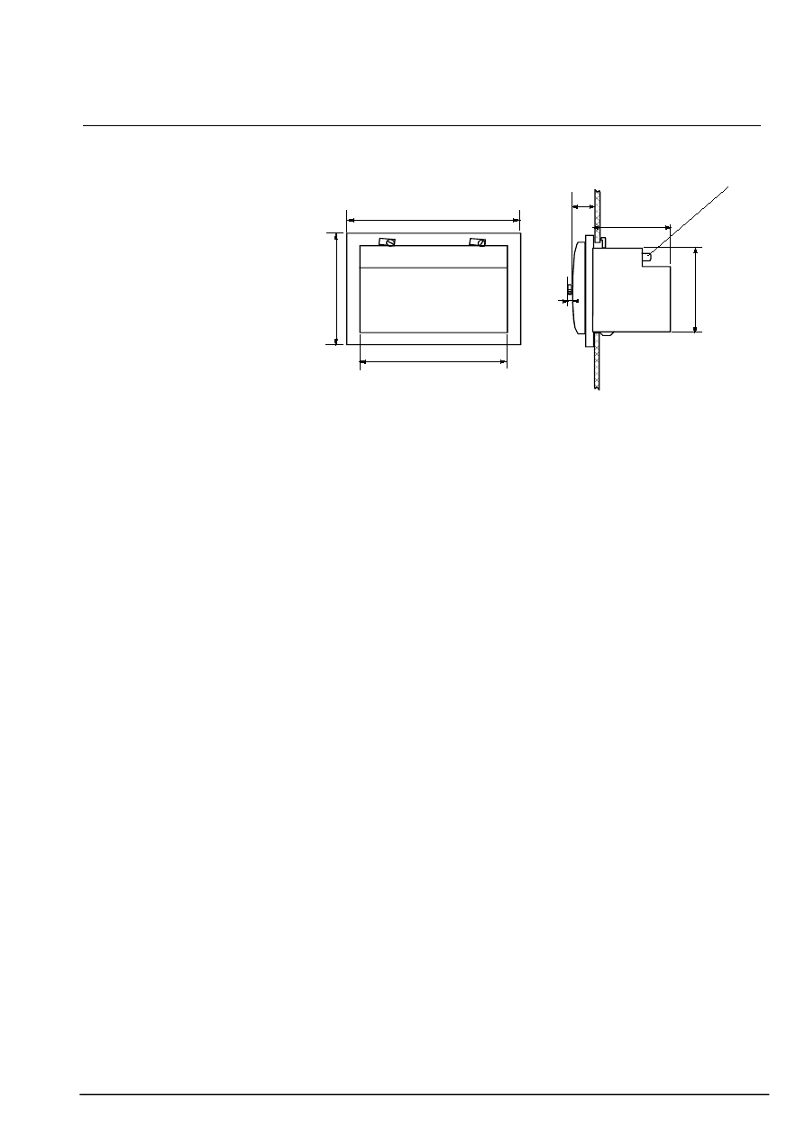
7. technical characteristics (cont’d)
dimensions
159
179
139
22
raccordemen
90
127
6
technical manual VIP300
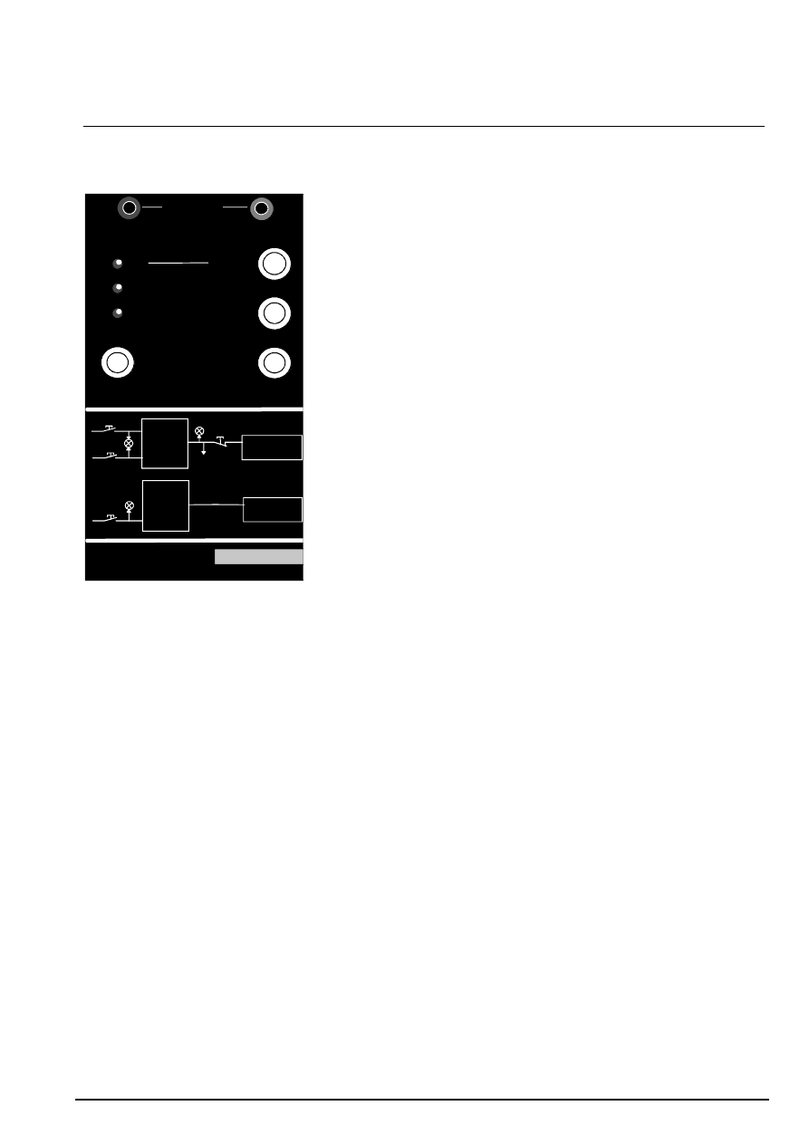
20
8. testing of the VIP300 and use of the VAP6
presentation of the VAP6
battery test
phase overcurrent
on
test in progress
trip
earth fault
VAP 6
trip
inhibition
+
-
external mitop
VIP30
VIP35
VIP300
VIP50
VIP37
mitop
circuit breaker
earth fault
phase
overcurrent
trip
trip
test
VIP11,11R
VIP12R
VIP13
VIP17
VIP200,201
circuit breaker
phase
overcurrent
test
mitop
external
mitop
inhibition
- VAP6 front panel -
The VAP6 is a portable unit that is
connected to the VIP300 to carry out
simplified testing.
The test can be carried out in the
following two cases:
- the VIP300 is already supplied by
the sensors.
- the VIP300 is not supplied. In this
case, the VAP6 batteries supply
power to the relay.
The test consists of:
- starting up the VIP300 central unit
self-testing sequence.
- injecting a stimulus to simulate a
phase fault.
- injecting a stimulus to simulate an
earth fault.
- checking tripping.
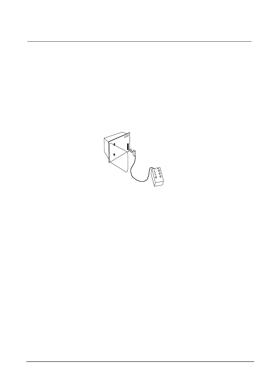
F
refer to the description of the test
in the section entitled "test sequence"
F
the VAP6 is supplied by batteries.
Therefore the parts of the VIP300
that run on AC current are not
checked using this method (input and
supply circuits).
push-buttons
n
battery test: if the batteries are
OK, the "on" indicator lights up while
the button is pushed.
n
phase overcurrent: it sends the
phase protection test stimulus. The
stimulus is equivalent to 20 times the
setting current Is.
n
earth fault: it sends the earth
protection test stimulus. The stimulus
is equivalent to 20 times the earth
setting current Ios.
n
trip inhibition: press the "trip
inhibition" button if the VIP300 test
should be carried out without tripping
of the circuit breaker. Circuit breaker
tripping is inhibited while the ’trip
inhibition" button is pressed, even if
the tripping order results from a real
fault.
indicators
n
on: indicates that the batteries are
operating. Also lights up when the
battery test is carried out by pressing
"battery test".
n
test in progress: confirms sending
of the test stimulus to the VIP300.
n
trip: it is used to test other relays in
the VIP range. It is not to be
considered for the VIP300 test. (it
lights up for a transient period when
the VIP300 sends a tripping order;
whether or not the circuit breaker is
inhibited).
"external mitop" output
It may be used to connect an
auxiliary mitop designed, for instance,
to stop a stop watch during operating
tests. The mitop is triggered at the
same time as the circuit breaker
mitop. It is not inhibited by pressing
the "trip inhibition" button.
batteries
n
the batteries are normally
deactivated and are automatically
activated when the VAP6 is
connected to the VIP300.
They are activated in the following
cases:
- pressing the "battery test" button.
- direct connection to a VIP3X or
VIP5X relay.
- connection to the adapter cord
designed for testing of the VIP1X or
VIP2X relays.
n
to install or change the batteries,
open the unit by removing the 4
screws on the bottom of the unit. Be
sure to use the correct polarities.
technical characteristics
supply:
3 x 9V 6LR61
batteries
weight:
0.45 kg
dimensions: 93x157x45
technical manual VIP300
21
8. testing of the VIP300 and use of the VAP6 (cont’d)
VAP6 test sequence
The test may be carried out with or
without current in the sensors. During
the test operations, all the VIP300
settings are effective; the relay
should perform in accordance with
the settings. During the test, the relay
remains operational and will give a
tripping order in the event of a fault,
unless the "trip inhibition" button is
pressed.
n
connect the VAP6 to the "VAP6
test plug". The VAP6 batteries are
activated and the "on" indicator lights
up.
n
press the VIP300 "reset" button.
- if the 2 "trip" indicators were yellow,
they become black.
- the 2 red I> and Io> indicators of the
VIP300 light up for about 3s to
indicate that the central unit has
correctly performed self-testing.
n
press the "trip inhibition" button if
the test should be carried out without
tripping of the circuit breaker.
F
be sure to continue pressing the
"trip inhibition" button throughout the
time it takes to send the stimulus.
n
press the "phase overcurrent"
button to send the phase protection
test stimulus.
- continue pressing the button
throughout the duration of the
stimulus. The stimulus represents
about 20 times the setting current Is.
- the VAP6 "test in progress" indicator
lights up to confirm the sending of the
stimulus to the VIP300 relay.
- the red "I>" indicator of the VIP300
blinks during the time delay period.
- then the VIP300 phase "trip"
indicator turns yellow.
- the circuit breaker trips if it is not
inhibited.
F
if the "phase overcurrent" button is
held down after tripping, the VIP300
starts the time delay/tripping cycle
again; this is normal operation.
In that case:
- the VAP6 red "trip" indicator lights
up for a transient period each time
there is a trip.
- depending on the time delay setting,
the VIP300 red "I>" indicator may be
off or blink rapidly and/or in an
irregular manner.
n
press "earth fault" to test operation
of the earth protection. The stimulus
injected is equal to 20 times the
setting current Ios. Use the same
procedure as for the phase protection
test.
n
disconnect the VAP6.
In order to save batteries, do not
leave the VAP6 connected to the
relay unnecessarily.

technical manual VIP300
22
Notes

technical manual VIP300
23
Notes

technical manual VIP300
24
Schneider Electric SA
Postal address
F-38050 Grenoble cedex 9
Tél : +33 (0)4 76 57 60 60
Télex : merger 320842F
http://www.schneider-electric.com
Rcs Nanterre B 954 503 439
Rcs Nanterre B 954 503 439
As standards, specifications and designs change
from time to time, please ask for information
given in this publication
Publishing: Schneider Electric SA
Design, production: Schneider Electric SA
Printing:
This document has been
printed on ecological paper
PCRED399008EN
ART. 20499
04 / 1999
Document Outline
Wyszukiwarka
Podobne podstrony:
06 INSTRUCTION MANUAL FUEL OIL FILTER 12153 3188 E
06 MANUAL TRANSAXLE (C153)(1)
06 MANUAL TRANSAXLE (C153)(1)
Chartek QC Manual 30 Jan 06
Interchar 212 Application Manual 7 june 06
06 MANUAL TRANSAXLE (C153)(1)
MT st w 06
Kosci, kregoslup 28[1][1][1] 10 06 dla studentow
06 Kwestia potencjalności Aid 6191 ppt
06 Podstawy syntezy polimerówid 6357 ppt
06
06 Psych zaburz z somatoformiczne i dysocjacyjne
GbpUsd analysis for July 06 Part 1
Probl inter i kard 06'03
06 K6Z4
więcej podobnych podstron