ID Rev.
Date
APP MAN IC212 UK
07 07/06/06
Interchar
®
212 Application Manual
Page 1 of 37
©International Paint Limited, 2006
This document and its contents are the copyright of International Paint Limited and may not be reproduced in whole or in part without the
express permission of International Paint Limited
Interchar 212 Application Manual
Rev. 07 – 7 June 2006
Prepared by:
INTERNATIONAL PAINT LTD.
www.interchar.com
Fire protection performance and pre-fire durability critically depend on the correct application of
the system.
International Protective Coatings requires that the Interchar fireproofing systems are installed by
qualified applicators in strict accordance with the instructions contained in this Application
Manual.
Applicators must make direct contact with International Protective Coatings to ensure adequate
training in the application of Interchar 212 has taken place PRIOR to any commencement of a
project.
ID Rev.
Date
APP MAN IC212 UK
07 07/06/06
Interchar
®
212 Application Manual
Page 2 of 37
©International Paint Limited, 2006
This document and its contents are the copyright of International Paint Limited and may not be reproduced in whole or in part without the
express permission of International Paint Limited
I
I
n
n
t
t
e
e
r
r
c
c
h
h
a
a
r
r
2
2
1
1
2
2
A
A
p
p
p
p
l
l
i
i
c
c
a
a
t
t
i
i
o
o
n
n
M
M
a
a
n
n
u
u
a
a
l
l
R
R
e
e
v
v
i
i
s
s
i
i
o
o
n
n
s
s
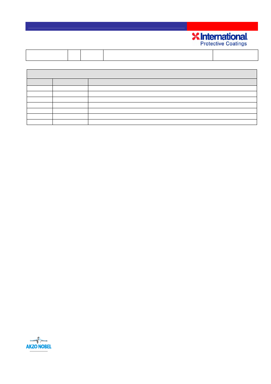
R
R
E
E
V
V
.
.
D
D
A
A
T
T
E
E
R
R
e
e
v
v
i
i
s
s
i
i
o
o
n
n
N
N
o
o
t
t
e
e
s
s
01 30/03/05
Original
02
03/05/05
Review within WWPC Technical
03
24/06/05
Feedback from Asia Pacific
04
19/07/05
Section 11.2 removed
05
05/08/05
Clarification of mix rations in 5.6
06
08/09/05
Feedback from UK
07 07/06/06
IMPORTANT NOTE:
This Manual covers Interchar 212 only.
The original language of the manual is English. In the event of discordance with successive translations, the company and
addressees of the manual must make reference to the English edition.
The document is identified by a code and revision date. This information is written in the footer of every page as follows:
-
The identification code, which consists of an abbreviation of the subject (“APP”: application), document type (“MAN”:
manual), product (IC212 ) and the language version (UK: English, IT: Italian etc.);
-
The number and date of the revision: the revision date corresponds to the date of approval.
The manual is distributed internally and externally with the aim of providing consistent information to all parties involved in the
application of Interchar 212 fireproofing systems.
This manual uses both metric and American Imperial units of measure (in brackets).
International Paint Ltd., International Paint Inc., etc are referred to as “International” in this manual.
Unauthorized changes or reproduction of the manual are forbidden.
The information given in this manual is not intended to be exhaustive: any person applying the product by any method other than
that specifically recommended in this manual without first obtaining our written confirmation as to the suitability of the proposed
method does so at his own risk. We try very hard to ensure that all advice we give about application of our product (whether in
this manual or otherwise) is correct but we have no control over either the quality or condition of the substrate or the many
factors affecting application of the product
The information contained in this manual is liable to modification from time to time in the light of experience and our policy of
continuous product development. It is the user’s responsibility to check that this manual is current prior to using the product.
Unless we agree differently in writing all our goods and related technical advice are supplied on our standard conditions of sale,
a copy of which is available on request.
This document must be read in conjunction with the Product and Safety datasheets for Interchar 212

ID Rev.
Date
APP MAN IC212 UK
07 07/06/06
Interchar
®
212 Application Manual
Page 3 of 37
©International Paint Limited, 2006
This document and its contents are the copyright of International Paint Limited and may not be reproduced in whole or in part without the
express permission of International Paint Limited
Table of Contents
1.0 INTRODUCTION ........................................................................................................... 5
2.0 SYSTEM DESCRIPTION............................................................................................... 6
3.0 SURFACE PREPARATION ........................................................................................... 7
4.0 PRIMERS ....................................................................................................................10
5.0 INTERCHAR 212 APPLICATION WITH PLURAL SPRAY EQUIPMENT INCLUDING
EQUIPMENT REQUIREMENTS........................................................................................ 12
5.1 Packaging ................................................................................................................ 12
5.2 Ambient Conditions................................................................................................ 12
5.3 Surface Cleanliness................................................................................................ 12
5.4 Primer and Surface Preparation ............................................................................ 12
5.5 Storage Conditions................................................................................................. 13
5.6 Plural Component Spray Equipment..................................................................... 13
5.7 Ratio Checks ........................................................................................................... 14
5.8 Spray Application ................................................................................................... 16
5.9 Thickness Measurement ........................................................................................ 18
5.10 Surface Finish ....................................................................................................... 19
6.0 APPLICATION WITH MODIFIED SINGLE LEG AIRLESS SPRAY EQUIPMENT
INCLUDING EQUIPMENT REQUIREMENTS ................................................................... 20
6.2 Ambient Conditions................................................................................................ 20
6.3 Surface Cleanliness................................................................................................ 20
6.4 Primer and Surface Preparation ............................................................................ 21
6.5 Storage Conditions for Single Leg Airless Spray Equipment Application ........ 21
6.6 Spray Application ................................................................................................... 22
6.7 Mixing ...................................................................................................................... 22
6.8 Single Leg Airless Spray Equipment .................................................................... 22

ID Rev.
Date
APP MAN IC212 UK
07 07/06/06
Interchar
®
212 Application Manual
Page 4 of 37
©International Paint Limited, 2006
This document and its contents are the copyright of International Paint Limited and may not be reproduced in whole or in part without the
express permission of International Paint Limited
6.9 Thickness Measurement ........................................................................................ 22
6.10 Surface Finish ....................................................................................................... 22
7.0 HAND/TROWEL APPLICATION.................................................................................. 23
7.1 Ambient Conditions................................................................................................ 23
7.2 Surface Cleanliness................................................................................................ 23
7.3 Primer and Surface Preparation ............................................................................ 23
7.4 Storage Conditions................................................................................................. 23
7.5 Hand/Trowel Application........................................................................................ 23
7.6 Water Contamination.............................................................................................. 23
7.7 Mixing ...................................................................................................................... 24
7.8 Thickness Measurement ........................................................................................ 24
7.9 Surface Finish ......................................................................................................... 24
8.0 TOPCOATS ................................................................................................................. 25
9.0 REMOVAL AND REPAIR, ADDITIONAL WORK, WELD CUTBACK AND REPAIR OF
DAMAGED AREAS............................................................................................................ 27
9.1 Removal................................................................................................................... 27
9.2 Weld Cutback .......................................................................................................... 27
10.0 SAFETY AND ENVIRONMENT ................................................................................. 29
11.0 SPECIAL APPLICATIONS......................................................................................... 30
11.1 Repair Procedure for Damaged or Delaminated Interchar 212 ......................... 30
APPENDIX A – Technical Note TN/F/083 “Overcoating of aged and zinc primers” ........... 34

ID Rev.
Date
APP MAN IC212 UK
07 07/06/06
Interchar
®
212 Application Manual
Page 5 of 37
©International Paint Limited, 2006
This document and its contents are the copyright of International Paint Limited and may not be reproduced in whole or in part without the
express permission of International Paint Limited
1.0 INTRODUCTION
This Application Manual contains instructions on how to install Interchar 212 fireproofing systems.
Passive fireproofing materials prevent potentially catastrophic structural failures from occurring by
providing an insulating shield against the intense heat of a fire. The Interchar 212 fireproofing
systems is the result of over 30 years of research and development and possesses extensive
certification for a wide range of fire protection ratings.

ID Rev.
Date
APP MAN IC212 UK
07 07/06/06
Interchar
®
212 Application Manual
Page 6 of 37
©International Paint Limited, 2006
This document and its contents are the copyright of International Paint Limited and may not be reproduced in whole or in part without the
express permission of International Paint Limited
2.0 SYSTEM DESCRIPTION
Interchar 212 passive fireproofing system consists of a two pack epoxy intumescent mastic.
Interchar 212 can provide effective fire protection to a very wide range of steel structures in
cellulosic fire scenarios, whilst also providing protection against corrosion. In a fire, Interchar 212
fireproofing will intumesce (expand) to a thickness much greater than that of the applied coating to
form an insulating blanket of char. It is this char and its formation that protects the substrate from
fire damage.

ID Rev.
Date
APP MAN IC212 UK
07 07/06/06
Interchar
®
212 Application Manual
Page 7 of 37
©International Paint Limited, 2006
This document and its contents are the copyright of International Paint Limited and may not be reproduced in whole or in part without the
express permission of International Paint Limited
3.0 SURFACE PREPARATION
Degreasing
Definition:
The removal of all visible oil, grease or other soluble contaminants (SSPC-SP1).
Comments:
The presence of surface oil or grease prevents a coating from properly adhering to the substrate
and can lead to rapid failure of the whole system. For this reason, all visible oil, grease and other
soluble contaminants must be removed before the application of both primer and Chartek.
Degreasing is also important before blast cleaning activities.
Acceptable methods of degreasing include:
¾ wiping or scrubbing the surface with rags or brushes wetted with solvent (NB: use clean
solvent for the final wiping)
¾ steam cleaning using detergents or emulsion/alkaline cleaners followed by steam or fresh
water wash to remove detrimental residues
The applicator must select the method most appropriate to the situation, giving due consideration to
applicable health and environmental regulations. In all cases, International Protective Coatings
recommends removing any heavy oil or grease first by scraper and completing the degreasing
activity with a thorough fresh water rinse.
Recommendations regarding degreasing of primers must also be observed at all times.
Blast cleaning
Definition of degrees of cleanliness:
Sweep (Brush-off) blast:
Removal of all loose mill scale, loose rust and loose coating with abrasive blast cleaning (Sa 1,
SSPC-SP 7, NACE No. 4)
Near white blast cleaning:
A near white blast cleaned surface, when viewed without magnification, shall be free of all visible oil,
grease, dust, dirt, mill scale, rust, coating, oxides, corrosion products and other foreign matter
except for staining (light shadows, streaks or discolorations caused by stains of rust, mill scale or
previously applied coatings) limited to no more than 5% of the surface (Sa 2½, SSPC-SP10, NACE
No. 2).
Comments:

ID Rev.
Date
APP MAN IC212 UK
07 07/06/06
Interchar
®
212 Application Manual
Page 8 of 37
©International Paint Limited, 2006
This document and its contents are the copyright of International Paint Limited and may not be reproduced in whole or in part without the
express permission of International Paint Limited
Blast cleaning is widely accepted as being the best way of preparing a metallic substrate (usually
steel) before application of a protective coating and it is a very important part of the whole
application process. When a primer is used, blast cleaning should be carried out in accordance with
the primers instructions. In all cases, the following general requirements must be observed:
Degree of cleanliness:
The general requirement is near-white blast cleaning to Sa 2½ (ISO 8501-1), equivalent to
SSPC-SP10 or NACE No. 2.
Blast profile:
The blast profile (R
z
)
must be between 50 and 75 microns (2-3 mils) for steel substrates. This may
vary for other substrates. If in doubt, consult International Protective Coatings. The recommended
method for measuring the blast profile is with replica tape.
Angular abrasive must be used in order to produce a suitably sharp surface profile. If in doubt,
consult International Protective Coatings.
Wet blasting is only permitted with the express written consent of International Protective Coatings.
When the substrate has been hot-dip galvanised, International Protective Coatings recommends a
minimum sweep (brush-off) blast to Sa 1 (ISO 8501-1), equivalent to SSPC-SP7 or NACE No. 4,
sweep abrasive blast cleaning in order to produce a suitably roughened surface. The blast profile
(R
z
)
should be between 50 and 75 microns (2-3 mils).
Power tool cleaning
Definition: Removal of all loose mill scale, loose rust, loose paint and other loose detrimental foreign
matter (SSPC-SP11).
ID Rev.
Date
APP MAN IC212 UK
07 07/06/06
Interchar
®
212 Application Manual
Page 9 of 37
©International Paint Limited, 2006
This document and its contents are the copyright of International Paint Limited and may not be reproduced in whole or in part without the
express permission of International Paint Limited
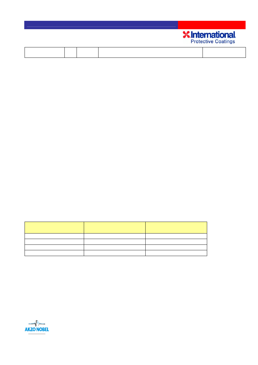
Table 1: Interchar 212 Surface Preparation Chart
OPERATION
REQUIRED
STEEL
GALVANISED STEEL
Degreasing
9
9
Power Tool Cleaning
See Note 2
Near White Blast Cleaning
9
Sweep (Brush-off) Blast
Cleaning
9
Blow down
9
9
Primer
9
9
COMMENTS
Blast profile
must be
50-75 microns
(2-3 mils)
Epoxy
primer only
50–75 microns
(2-3 mils) blast profile
Note 1:
If there is a risk of oxidisation of the surface prior to application of Interchar 212 a
suitable primer should be used. Contact International Protective Coatings.
Note 2:
Small areas (not exceeding 1m
2
(1550in
2
), for example welds and local repair areas,
should be prepared by power discing with a carborundum disc or by needlegun to
achieve a clean, roughened surface in accordance with SSPC-SP11, power tool
cleaning.. Power tool cleaning brushing is not an acceptable primary surface
preparation method for steel.

ID Rev.
Date
APP MAN IC212 UK
07 07/06/06
Interchar
®
212 Application Manual
Page 10 of 37
©International Paint Limited, 2006
This document and its contents are the copyright of International Paint Limited and may not be reproduced in whole or in part without the
express permission of International Paint Limited
4.0 PRIMERS
It is possible to apply Interchar 212 to freshly prepared substrate (as described see Section 3.0).
However, depending on environmental factors (temperature, time, humidity etc), it may be
necessary to prime the substrate to prevent deterioration of the blast.
To ensure optimal bonding between the Interchar 212 and substrate, correct primer type and
thickness are required.
Primer Thickness
Optimal bonding is achieved when the primer’s dry film thickness (dft) is sufficient to just cover the
peaks of the blast profile and maintain a rust free condition prior to application of Interchar 212.
Excessive thickness produces weaker cohesive strength and may lead to premature failure of the
primer system. For this reason, careful monitoring and measurement of primer thickness is
required. Dft measurement should be carried out with a gauge that has just been calibrated on a
smooth calibration plate (no compensation for blast profile is to be made).
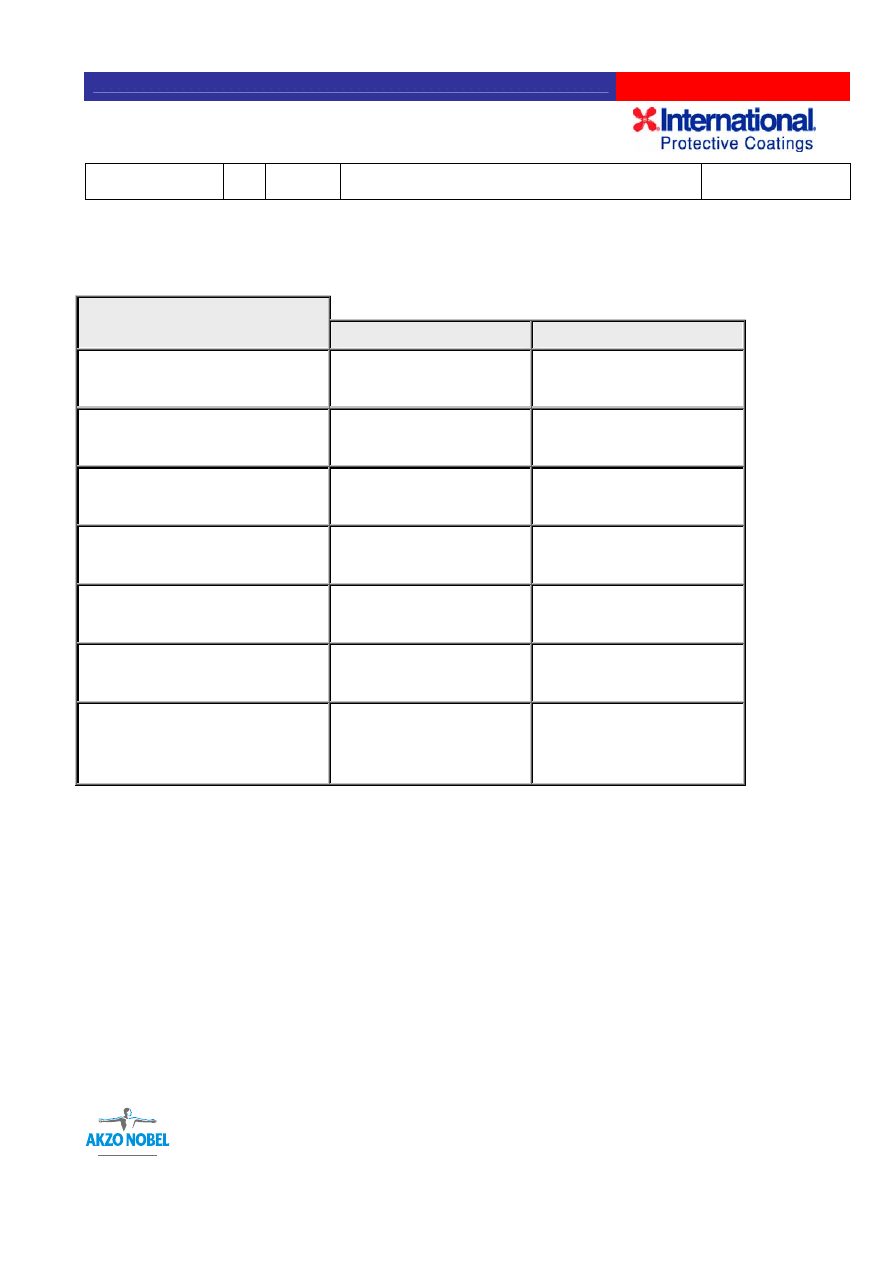
The maximum allowable primer system dft’s are summarized in the following table:
Table 2: Primer System Maximum Dft’s
Primer System
Dry Film Thickness
Normal Areas
Overlap Areas
Epoxy primer (e.g Intercure 200)
50-75 microns
(2-3 mils)
100 microns
(4 mils)
Epoxy zinc primer (e.g Interzinc 52)
50-75 microns
(2-3 mils)
100 microns
(4 mils)
Epoxy zinc primer plus tie coat
75-110 microns
(3-4.4 mils)
125 microns
(5 mils)
NOTE: “Overlap areas” refers to internal angles of structural sections and other areas where multiple
spray passes are unavoidable.
Reduction of Excessive Primer Thickness
Excessive primer thickness should be reduced to the dft’s indicated in the foregoing Table 2. The
preferred method to be used is abrasive sweep blasting. Sanding with P80-P100 grade aluminium
oxide abrasive paper may be suitable for small areas; however, care should be taken to prevent
polishing of the surface which would lead to inadequate adhesion of the Interchar 212. Polishing
must be avoided and frequent changes of the abrasive paper should be made.
After primer reduction surfaces should be cleaned of dust and contaminants, potable water washed
and thoroughly dried prior to the application of Interchar 212.

ID Rev.
Date
APP MAN IC212 UK
07 07/06/06
Interchar
®
212 Application Manual
Page 11 of 37
©International Paint Limited, 2006
This document and its contents are the copyright of International Paint Limited and may not be reproduced in whole or in part without the
express permission of International Paint Limited
Primer Type
Please consult with International Protective Coatings for a list of qualified primers. Care should be taken
to ensure that systems have reached sufficient levels of cure prior to overcoating with
Interchar 212.
Generally this will not be less than three days.
It is the responsibility of the applicator installing the
Interchar 212
to assess the condition of the primer
coating before the Interchar 212 is applied.
Should the primer’s suitability for the overcoating with
Interchar 212
be in doubt in any way, International
Protective Coatings should be consulted before the application of
Interchar 212.
NOTE: Epoxy tie coat (25-35 microns dft) should be used with zinc primers if
Interchar 212
is not
applied immediately after the primer has cured or if the primer is exposed to humid or outdoor conditions
prior to application of
Interchar 212.

ID Rev.
Date
APP MAN IC212 UK
07 07/06/06
Interchar
®
212 Application Manual
Page 12 of 37
©International Paint Limited, 2006
This document and its contents are the copyright of International Paint Limited and may not be reproduced in whole or in part without the
express permission of International Paint Limited
5.0 INTERCHAR 212 APPLICATION WITH PLURAL SPRAY
EQUIPMENT INCLUDING EQUIPMENT REQUIREMENTS
5.1 Packaging
For plural component equipment, Interchar 212 is supplied in a 50kg (110lb) kit comprising 35.48kg
(78.2lb) grey coloured resin (Part A) in 2 x 20 litre (2 x 5.3 US gallon) pails and 14.52kg (32lb) of
light coloured hardener (Part B) in a 20 litre (5.3 US gallon) pail.
5.2 Ambient Conditions
Suitable application conditions are of critical importance for the successful application of Interchar
212. Consequently, it should only be applied when the ambient conditions are within the following
parameters:
¾ Air temperature: minimum 10ºC
¾ Relative humidity: maximum 85%
¾ Surface temperature: at least 3ºC above dew point temperature
Interchar 212 may be applied at an air temperature minimum 5
o
C using plural spray equipment only,
recognising that the time to cure will in such applications be extended. Additionally, there may also
be a higher propensity for amine bloom formation which would affect overcoating with further layers
of Interchar 212 where required, and may affect overcoating with topcoats. For such low air
temperature applications, plural equipment is the only recommended dispensing method.
5.3 Surface Cleanliness
To ensure proper adhesion of Interchar 212 to the substrate (or primer) , the surfaces to be coated
must be dry and free from oil, grease, dirt or any other contaminants that have been deposited since
surface preparations were completed.
It is the applicator’s responsibility to inspect all surfaces to be coated and clean them if necessary
(see the notes on degreasing in Section 3).
Ambient conditions are of critical importance for a successful application. If they cannot be kept
within the above parameters, Interchar 212 application may only proceed if adequate environmental
protection is provided.
5.4 Primer and Surface Preparation
It is the applicator’s responsibility to verify that the correct primer, thickness and cure requirements
are complied with.
It is also the applicator’s responsibility to ensure that the preparation of the surface which is to be
overcoated with Interchar 212 is in accordance with the requirements of this Application Manual and

ID Rev.
Date
APP MAN IC212 UK
07 07/06/06
Interchar
®
212 Application Manual
Page 13 of 37
©International Paint Limited, 2006
This document and its contents are the copyright of International Paint Limited and may not be reproduced in whole or in part without the
express permission of International Paint Limited
other documents that may be applicable. For acceptance of the primed surface, checks shall
include, but not be limited to, the following:
a)
The surface profile is in accordance with this Application Manual and other documents that
may be applicable.
(b) The surface condition at the time of primer application, both in terms of degree of visual
cleanliness and presence of surface contaminants.
(c)
That the primer is qualified by International Protective Coatings for use with Interchar 212.
(d)
That the Applicator has access to, and is familiar with, the primer.
(e)
Primer thickness values shall not exceed the tolerance levels stated in Section 4, Table 2:
“Primer System Maximum Dfts”.
(f)
Age and condition of primer at point of overcoating with Interchar 212. See Appendix B,
Technical Note TN/F/083 “Overcoating of aged and zinc primers”.
It is the applicator’s responsibility to ensure that the primed surface and the primer itself are in an
acceptable condition for overcoating with Interchar 212. Such factors as ageing of the primer
(degradation and surface chalking), contamination, rust bloom, etc. shall be considered when
determining a surface’s suitability before overcoating with Interchar 212. Where there is any doubt
as to a primer’s acceptance, the primer manufacturer should be consulted.
5.5 Storage Conditions
Interchar 212 should be stored indoors and out of direct sunlight.
The following storage temperature ranges must be maintained:
1. General storage: Minimum 1ºC (34ºF), maximum 30ºC (86ºF)
2. Material temperature for plural component spray application:
30–34ºC (86–93ºF) for 24 hours (maximum 48 hours) prior to use
Accelerated methods of heating the Interchar 212 containers prior to use, such as electrical
heaters in direct contact with the containers or hot water baths, are not permitted. Such
methods can cause overheating of the outer layers of material in the container, which may produce
undesirable changes to its properties (including shorter pot life).
5.6 Plural Component Spray Equipment
As Interchar 212 is a thixotropic material, it is most efficiently applied with purpose built hot spray
plural component pumps, which have the advantage of not requiring any premixing of the two parts.
For Interchar 212 the optimum temperatures are as follows:
Part A
Part B
Tank temperature:
60
o
C (140
o
F) 50
o
C (122
o
F)
Tank stirrers:
10rpm
15rpm

ID Rev.
Date
APP MAN IC212 UK
07 07/06/06
Interchar
®
212 Application Manual
Page 14 of 37
©International Paint Limited, 2006
This document and its contents are the copyright of International Paint Limited and may not be reproduced in whole or in part without the
express permission of International Paint Limited
Line heaters:
55-65
o
C (131-149
o
F) 45-55
o
C (113-131
o
F)
Tank pressures:
5.5 bar (80 psi)
2.75 bar (40 psi)
Material exiting the gun:
50-55
o
C
Displacement pump pressure:
172-241 bar (2500-3500 psi)
In order to ensure trouble free operation of this type of pump the material must be maintained at the
correct temperature. It is therefore necessary to provide controlled heated storage for the
Interchar 212 and advisable to place the machine in a modified insulated container for work at low
air temperatures.
The importance of keeping all spray equipment clean and efficient cannot be overstated, as down
time is very costly. For this reason a skilled and experienced machine operator is a vital component
of the team.
Machines built to spray Interchar 212 are supplied by a number of companies. Each supplier
provides instructions on machine operation and maintenance. International Protective Coatings
should always be consulted regarding the suitability of spray equipment.
Because of the larger volume of material delivered by these machines, crew sizes are larger to keep
up with the gun. The material is delivered hot and therefore must be worked more quickly than
conventional spray.
5.7 Ratio Checks
It is important that the delivery ratio of plural spray pumps is regularly checked. As a minimum, a
ratio check by weight should be performed at the start up of each day’s production and again if the
machine is shut down and restarted for any reason. Use the following procedure for ratio checks by
weight:
1. Weigh clean empty Parts A and B containers and note the respective weights.
2. Place the containers under the ratio check valves located on the mixing block and open the
valves at exactly the same time.
3. Close the valves when the containers are at least half full at exactly the same time.
4. Find the net weight of each part by subtracting the weight of the containers.
5. Calculate the ratio of Part A to Part B as a percentage of the total weight.
Example:
Part A empty container weight – 2.3kg (5.0lb)
Part B empty container weight – 1.2kg (2.6lb)
Part A full container weight – 9.4kg (20.7lb)
Part B full container weight – 4.1kg ( 9.0lb)

ID Rev.
Date
APP MAN IC212 UK
07 07/06/06
Interchar
®
212 Application Manual
Page 15 of 37
©International Paint Limited, 2006
This document and its contents are the copyright of International Paint Limited and may not be reproduced in whole or in part without the
express permission of International Paint Limited
Part A net weight – 7.1kg (15.7lb)
Part B net weight – 2.9kg ( 6.4lb)
As a minimum a ratio check should be carried out at the start of each shift and after each machine
shutdown and restart. In addition to the ratio checks, constant checking of the displacement pump
pressure gauges and the colour of the mixed Interchar should be carried out by the machine
operator and sprayer respectively.
Parts A:B as a ratio of total weight = 2.45:1
The weight ratio for Interchar 212 is 2.49:1.
The acceptable ratio range of Part A:Part B is:
2.37:1
Minimum
2.61:1
Maximum

ID Rev.
Date
APP MAN IC212 UK
07 07/06/06
Interchar
®
212 Application Manual
Page 16 of 37
©International Paint Limited, 2006
This document and its contents are the copyright of International Paint Limited and may not be reproduced in whole or in part without the
express permission of International Paint Limited
Operating parameters for plural component spray machines
1.
Storage tank temperatures
Part A:
max. 60
o
C (140
o
F)
Part B:
max. 50
o
C (122
o
F)
2.
In-line heater temperatures
Part A:
55-65
o
C (131-149
o
F)
Part B:
45-55
o
C (122-131
o
F)
3.
Hose heater temperature
60-70
o
C (140-158F)
4.
Gun exit temperature
50-55
o
C (122-131
o
F)
5.
Storage tank pressures
Part A:
5.50 bar (80 psi)
Part B:
2.75 bar (40 psi)
6.
Tank stirrer speed
Part A:
10rpm
Part B:
15rpm
7.
Displacement pump pressure
175-240 bar (2500-3500 psi)
Fluid lines and spray tips:
¾” I.D. fluid lines for Part A and ½” I.D. fluid lines for Part B.
0.035” to 0.041” I.D. “reverse-a-clean” airless spray tips
5.8 Spray Application
In order to ensure trouble free operation of this type of pump the material must be maintained at the
correct temperature. It is therefore necessary to provide controlled heated storage for the
Interchar 212 and advisable to place the machine in a modified insulated container for work at low
air temperatures.
There should be sufficient area available to spray and enough manpower to keep up with the gun.
Frequently shutting down spray machines causes wasted time and material spent cleaning and
causes pressure build up in the material lines and spray gun, which may represent a safety hazard.
Interchar 212 can be rollered to achieve a uniform thickness of the coat, which allows uniform build
up of subsequent coats and ultimately the correct final thickness. Rolling also serves to produce a
smooth surface finish, when required. Rollering can be achieved using a short nap roller dampened
with International Protective Coatings thinner GTA123 (or GTA822) .
Two precautions to take with rolling are:

ID Rev.
Date
APP MAN IC212 UK
07 07/06/06
Interchar
®
212 Application Manual
Page 17 of 37
©International Paint Limited, 2006
This document and its contents are the copyright of International Paint Limited and may not be reproduced in whole or in part without the
express permission of International Paint Limited
1. If the Interchar 212 has not gelled (started to cure) sufficiently, it can sag or slump.
2. Too much solvent on the roller can reduce the cure rate if it is forced into the wet
Interchar 212.
For subsequent coats, sufficient time must pass for the applied Interchar 212 to gel (“set up” or
partially cure) in order to support the weight of the additional material.
Preferably, subsequent coats should be applied when the previous coat is still tacky. Where
practicalities prevent “wet on wet” application, overcoating time should be reduced to a minimum.
When the overcoating time is longer than 24 hours, a sprayed holding coat should be applied to
leave the Interchar 212 with a good key to improve the adhesion of the next coat. The holding coat
is produced by boosting the Interchar 212 temperature (in the plural component spray equipment)
and/or raising the pump output pressure to give a wide fan and increased atomisation. The spray
pass is much faster than normal and the result is a coarse finish that promotes good bonding with
subsequent coats.
It is imperative that surfaces are clean and thoroughly dry before additional coats are applied.
The final coat, when applied to a ‘wet’ surface, should be sufficiently thick to allow good ‘flowing out’
and to minimise surface roughness and to achieve the specified final thickness.
In applying a final coat to a hardened surface the thickness should be no less than 2mm to ensure
adequate adhesion to the hardened surface.
When spraying in cold conditions, the pump should be located in a heated area, ideally the same
area that is used to store the Interchar 212 at a sprayable temperature. Hoses should be insulated
and heated and ambient temperature parameters must be frequently checked and maintained.
In hot conditions, the spray unit and Interchar 212 must be located in an air-conditioned
environment. Hoses should be insulated and wrapped with heat reflecting tape. It may also be
necessary to raise hoses above the ground in extremely hot environments. High substrate
temperatures should be avoided by providing suitable shade cover and air-conditioning of the area
immediately surrounding the workface may also be necessary.
CAUTION: If rain or condensation occurs during application or shortly thereafter, moisture
may be absorbed into the uncured material. In addition, an amine bloom may form on the
Interchar 212 surface. These conditions will affect intercoat adhesion.
Take the following action if (fresh) water contamination occurs.

ID Rev.
Date
APP MAN IC212 UK
07 07/06/06
Interchar
®
212 Application Manual
Page 18 of 37
©International Paint Limited, 2006
This document and its contents are the copyright of International Paint Limited and may not be reproduced in whole or in part without the
express permission of International Paint Limited
Cured Interchar 212:
¾
Dry and solvent wipe
Uncured Interchar 212:
¾ Remove source of moisture
¾ Allow Interchar 212 to cure
¾ Dry and solvent wipe
¾ Remove and replace all uncured material
5.9 Thickness Measurement
As the fire protection rating is determined by the Interchar 212 thickness, it is imperative that
applicators constantly measure and record thicknesses during application.
Interchar 212 is a 100% volume solids product, so wet and dry film thicknesses are the same.
The following procedure for thickness measurement must be followed:
A. Method for measuring wet thickness:
The recommended method of measuring wet thickness is to use a pre-cut bridge gauge having a
width of approximately 25mm (1”), typically made from a putty knife. Notch or pin gauges are not
acceptable because they limit the measurement to one point. The gauge should just touch the
rolled surface. International Protective Coatings strongly recommends the continuous use of the
bridge gauge by all members of the application team (sprayer, trowellers and rollers). This is the
only way of ensuring the design thickness will be applied to the whole surface.
B. Method of measuring dry thickness:
Dry film thickness can be measured by either of the following methods:
¾ drilling a small hole approximately 2mm (
1
/
12
”) in diameter and checking the Interchar 212
thickness with a depth gauge (care must be taken not to damage the substrate and to
refill the holes with Interchar 212 as soon as possible);
¾ using an electromagnetic or ultrasound thickness gauge (care must be taken to correctly
calibrate on a smooth calibration plate the gauge immediately before taking any
readings).
It is recognized that the applied Interchar 212 layer will never be perfectly even and that areas of
lower than specified design thickness (“valleys”) are compensated by areas of higher than design
thickness (“peaks”).
Unless specifically stated otherwise in the project documentation, the minimum acceptable
thickness at any point shall not be less than 85% of the design thickness up to a maximum of
1.5mm (
1
/
16
”) less than the design thickness.
ID Rev.
Date
APP MAN IC212 UK
07 07/06/06
Interchar
®
212 Application Manual
Page 19 of 37
©International Paint Limited, 2006
This document and its contents are the copyright of International Paint Limited and may not be reproduced in whole or in part without the
express permission of International Paint Limited
In other words, for thicknesses up to and including 10mm (
3
/
8
”) the minimum allowable thickness is
85% of the design thickness. For thicknesses above 10mm (
3
/
8
”) the minimum allowable thickness
is the design thickness less 1.5mm (
1
/
16
”).
In all cases, the average thickness must be at least the specified passive fireproofing design
thickness.
The number of thickness readings to be taken should be decided by all parties before commencing
application, and ideally be made with reference to local standards for the measurement of fire
protection thicknesses.
Thickness readings should be accurately recorded on suitable quality control forms.
5.10 Surface Finish
The recommended method of measuring wet thickness is to use a pre-cut bridge gauge having a
width of approximately 25mm (1”), typically made from a putty knife. Notch or pin gauges are not
acceptable because they limit the measurement to one point. The gauge should just touch the
rolled Interchar 212 surface. International Protective Coatings strongly recommends the continuous
use of the bridge gauge by all members of the application team (sprayer, trowellers and rollers).
This is the only way of ensuring the design thickness will be applied to the whole surface.
Discontinuities, pinholes, voids or isolated deposits of excess thickness in the coating are not
acceptable.
Where there is the risk of water ponding on horizontal surfaces, the Interchar 212 should be sloped
sufficiently to avoid ponding.
Samples of the surface finish acceptable to the client, a reference area, must be prepared by
the applicator prior to job start-up. See the Quality Control Manual for Interchar 212
Fireproofing Systems Application for further details.
ID Rev.
Date
APP MAN IC212 UK
07 07/06/06
Interchar
®
212 Application Manual
Page 20 of 37
©International Paint Limited, 2006
This document and its contents are the copyright of International Paint Limited and may not be reproduced in whole or in part without the
express permission of International Paint Limited
6.0 APPLICATION WITH MODIFIED SINGLE LEG AIRLESS SPRAY
EQUIPMENT INCLUDING EQUIPMENT REQUIREMENTS
Application with single leg equipment is not as efficient as with plural component. More product
wastage will occur and manual labour requirements are likely to be higher. Usage rates up to 10%
higher than those stated on the data sheet are likely to occur.
International Protective Coatings recommends the use of the plural component equipment
whenever possible.
6.1 Packaging
Interchar 212 Packaging Sizes
For single component pumps and trowel application, Interchar 212 is supplied in a 20kg (44.1lb) kit,
comprising 14.2kg (31.3lb) of grey coloured resin (Part A) in a 22.7 litre (6 US gallon) short-filled pail
and 5.8kg (12.8lb) of light coloured hardener (Part B) in a 7.6 litre (2 US gallon) pail.
The following instructions are specified for Interchar 212 fireproofing installation and must be strictly
followed. The equipment requirements for Interchar 212 application are detailed in Section 6.7.
6.2 Ambient Conditions
Suitable application conditions are of critical importance for the successful application of Interchar
212. Consequently, Interchar 212 should only be applied when the ambient conditions are within
the following parameters:
¾ Air temperature: minimum 10ºC
¾ Relative humidity: maximum 85%
¾ Surface temperature: at least 3ºC above dew point temperature
6.3 Surface Cleanliness
To ensure proper adhesion of Interchar 212 to the primed substrate, the surfaces to be coated must
be dry and free from oil, grease, dirt or any other contaminants that have been deposited since
surface preparations were completed.
It is the applicator’s responsibility to inspect all surfaces to be coated and clean them if necessary
(see the notes on degreasing in Section 3).
Ambient conditions are of critical importance for a successful application. If they cannot be kept
within the above parameters, Interchar 212 application may only proceed if adequate environmental
protection is provided.

ID Rev.
Date
APP MAN IC212 UK
07 07/06/06
Interchar
®
212 Application Manual
Page 21 of 37
©International Paint Limited, 2006
This document and its contents are the copyright of International Paint Limited and may not be reproduced in whole or in part without the
express permission of International Paint Limited
6.4 Primer and Surface Preparation
It is the applicator’s responsibility to verify that the correct primer type (included in the list of
approved primers), thickness (as specified in Section 3) and cure (see Section 4) requirements are
complied with.
It is also the applicator’s responsibility to ensure that the preparation of the surface which is to be
overcoated with Interchar 212 is in accordance with the requirements of this Application Manual and
other documents that may be applicable. For acceptance of the primed surface, checks shall
include, but not be limited to, the following:
(a)
The surface profile is in accordance with this Application Manual and other documents that
may be applicable.
(b)
The surface condition at the time of primer application, both in terms of degree of visual
cleanliness and presence of surface contaminants.
(c)
That the primer is qualified by International Protective Coatings for use with Interchar 212.
(d)
That the applicator has access to, and is familiar with, the primer manufacturer’s application
data, and that the application process and environmental conditions are in compliance with
the primer manufacturer’s requirements.
(e)
Primer thickness values shall not exceed the tolerance levels stated in Section 4, Table 2,
“Primer system maximum dfts”.
(f)
Age and condition of primer at point of overcoating with Interchar 212.
It is the applicator’s responsibility to ensure that the primed surface and the primer itself are in an
acceptable condition for overcoating with Interchar 212. Such factors as ageing of the primer
(degradation and surface chalking), contamination, rust bloom, etc. shall be considered when
determining a surface’s suitability before overcoating with Interchar 212. Where there is any doubt
as to a primer’s acceptance, the primer manufacturer should be consulted.
NB: Overcoating a primer system with a 100% solids epoxy material such as Interchar 212 is
different to overcoating with further layers of material, especially solvented materials.
Consequently, it is important that the primer manufacturer should be fully informed of the
overcoating system and purpose of that system when directing any questions to the manufacturer
concerning overcoating. International Protective Coatings should be consulted where any doubt
exists.
6.5 Storage Conditions for Single Leg Airless Spray Equipment Application
See Section 5.5

ID Rev.
Date
APP MAN IC212 UK
07 07/06/06
Interchar
®
212 Application Manual
Page 22 of 37
©International Paint Limited, 2006
This document and its contents are the copyright of International Paint Limited and may not be reproduced in whole or in part without the
express permission of International Paint Limited
6.6 Spray Application
See Section 5.8
6.7 Mixing
If a single leg airless spray pump application is utilised, the Interchar 212 must be premixed. A
small amount of International Protective Coatings thinner GTA123 (or GTA822) is added to Part A
to reduce viscosity for mixing and spraying.
The amount required varies with initial material temperature but up to 1.0 litre (0.25 US gallons) may
be used per full kit of Interchar 212 and is added into Part A.
When Part A has reached a smooth consistency, Part B is then poured into the Part A container,
scraping the sides of the Part B container to empty it completely. The two parts are thoroughly
mixed together with a high torque, variable speed, paddle mixer of minimum 5 HP air motors (or
1000W/110V electric motor minimum) equipped with 250mm (10”) diameter paddle.
For best results, the mixer should be mounted on a power ram base to ease the effort required and
to allow vertical movement of the paddle blade. The mixing should begin slowly and speed built up
gradually.
Mix carefully until a smooth texture and uniform colour are achieved. Kits should not be mixed until
they are ready to be used.
6.8 Single Leg Airless Spray Equipment
Pump compression ratio: from 68:1 to 74:1 fitted with check valve to eliminate spray fan fluctuation.
Air Motor: Graco Premier (or equivalent) mounted on a power ram with a follower or induction
material feed plate.
¾” I.D. fluid line 15 to 20 metres (50 to 65 feet) long, rated to meet the required high
pressures of the pump.
½” I.D. whip line 4.5 metres (15 feet) long, rated to meet the required high pressures of the
pump.
High pressure airless spray gun fitted with swivel.
0.035” to 0.041” I.D. “reverse-a-clean” airless spray tips.
¾” I.D x 300 mm (12”) long in-line static mixer.
6.9 Thickness Measurement
See Section 5.9
6.10 Surface Finish
See Section 5.10
ID Rev.
Date
APP MAN IC212 UK
07 07/06/06
Interchar
®
212 Application Manual
Page 23 of 37
©International Paint Limited, 2006
This document and its contents are the copyright of International Paint Limited and may not be reproduced in whole or in part without the
express permission of International Paint Limited
7.0 HAND/TROWEL APPLICATION
The following instructions are specified for Interchar 212 fireproofing installation and must be strictly
followed.
7.1 Ambient Conditions
See Section 5.2
7.2 Surface Cleanliness
See Section 5.3
7.3 Primer and Surface Preparation
See Section 5.4
7.4 Storage Conditions
See Section 5.5
7.5 Hand/Trowel Application
Interchar 212 may also be applied manually using plasterer’s trowels. This has the advantage of
very little waste and virtually eliminates the need for masking.
Mixing is carried out using no more than 0.5 litres (0.15 US gallons) of International Protective
Coatings thinner GTA123 (or GTA822) is added to each full kit in order to maximise the thickness of
material that can be applied without sagging. The International Protective Coatings thinner GTA123
(OR GTA822) is added to Part A to reduce viscosity for mixing. Extreme care should be taken when
mixing to scrape the walls of the container into the central material to avoid applying any unmixed
material that might remain on the sides.
After a kit has been mixed, it may be spread out on flat clean boards or surfaces for each applicator
to work with. This prevents the material from curing too quickly and allows sufficient working time.
Alternatively the material may be applied directly from the pail.
Often trowel application will require less than a full kit of Interchar 212. In these cases, the required
amounts of Parts A and B should be accurately weighed out into a clean container and thoroughly
mixed. The correct ratio by weight for Interchar 212 is detailed in Section 5.7
7.6 Water Contamination
CAUTION: If rain or condensation occurs during application or shortly thereafter, moisture
may be absorbed into the uncured material. In addition, an amine bloom may form on the
Interchar 212 surface. These conditions will affect intercoat adhesion. In these instances
consult with International Protective Coatings for advice

ID Rev.
Date
APP MAN IC212 UK
07 07/06/06
Interchar
®
212 Application Manual
Page 24 of 37
©International Paint Limited, 2006
This document and its contents are the copyright of International Paint Limited and may not be reproduced in whole or in part without the
express permission of International Paint Limited
7.7 Mixing
For hand application Interchar 212 must be premixed. A small amount of International Protective
Coatings Thinner GTA123 (or GTA822) is added to Part A to reduce viscosity for mixing and
application.
The amount required varies with initial material temperature but up to 0.5 litres (0.13 US gallons)
may be used per full kit of Interchar 212.
When Part A has reached a smooth consistency, the Part B is then poured into the Part A container,
scraping the sides of the Part B container to empty it completely. The two parts are thoroughly
mixed together with a high torque variable speed paddle mixer, minimum 5 HP air motors (or
1000W/110V electric motor minimum) equipped with 250mm (10”) paddles. Mixing should continue
until a uniform colour is achieved.
For best results, the mixer should be mounted on a power ram base to ease the effort required and
to allow vertical movement of the paddle blade. The mixing should begin slowly and speed built up
gradually.
Mix carefully until a smooth texture and uniform colour are achieved. For a full kit this is
approximately 4 minutes. Kits should not be mixed until they are ready to be used.
7.8 Thickness Measurement
See Section 5.9
7.9 Surface Finish
For trowel application a smooth, even and rolled finish should be achieved. Discontinuities,
pinholes, voids or isolated deposits of excess thickness in the coating are not acceptable.
Where there is the risk of water ponding on horizontal surfaces, the Interchar 212 should be sloped
sufficiently to avoid ponding.
Samples of the surface finish acceptable to the client, a reference area, must be prepared by
the applicator prior to job start-up. See the Quality Control Manual for Interchar 212
Fireproofing Systems Application for further details.

ID Rev.
Date
APP MAN IC212 UK
07 07/06/06
Interchar
®
212 Application Manual
Page 25 of 37
©International Paint Limited, 2006
This document and its contents are the copyright of International Paint Limited and may not be reproduced in whole or in part without the
express permission of International Paint Limited
8.0 TOPCOATS
Interchar 212 has been extensively tested to industry recognised standards to demonstrate its
ability to withstand weather and environmental exposure, both with and without topcoats.
Generally Interchar 212 will be topcoated to meet owners’ colour schemes and finish requirements.
However, there are specific situations where the use of a topcoat is recommended, these include:
¾ To comply with UL 263 “Exterior Listing” requirements
¾ Coastal location conditions which are similar to an offshore environment
¾ Area of high UV exposure: like all epoxy products, Interchar 212 may chalk when
exposed to high levels of UV for prolonged periods. This can result in fading of the
original colour
¾ Areas of high moisture exposure
¾ Coarse sprayed finishes: a stippled finish may collect airborne contamination and result
in shading of the Interchar 212 surfaces
It is recommended that Interchar 212 is topcoated when it is sufficiently cured and the surfaces are
clean and dry, and prior to any possible contamination.
Recommended minimum overcoating intervals:
Temperature Minimum
o
C (
o
F) (hours)
15 (59)
12
25
(77)
6
40
(104)
4
Maximum overcoating times are dependent upon environmental exposure, type of topcoat system
used and other factors. The topcoat datasheet and working procedures must also be consulted
especially when utilising Interfine polysiloxanes as the maximum overcoat intervals are likely to be
shorter than the general ones quoted on the datasheet.
Excessive rollering with solvent can, in extreme cases, cause amine bloom on the surface of the
Interchar 212. This is not acceptable for application of topcoats. If amine bloom occurs, surfaces
must be suitably washed with one of the approved methods in Section 3, prior to application of any
topcoat.
Interchar 212 can be overcoated with a wide range of suitable topcoats to meet specific
requirements. For example, International Protective Coatings’ Interthane 990 and Interfine 878 are
recommended topcoats.
For heavy duty protection and to prevent shading on stippled finishes, International Protective Coatings
recommends one of the following topcoat systems:

ID Rev.
Date
APP MAN IC212 UK
07 07/06/06
Interchar
®
212 Application Manual
Page 26 of 37
©International Paint Limited, 2006
This document and its contents are the copyright of International Paint Limited and may not be reproduced in whole or in part without the
express permission of International Paint Limited
1. Two coats of Interthane 990 or Interfine 878 at 50 microns (2 mils) dft per coat.
2. One coat of epoxy polyamide primer at 75 microns (3 mils) dft plus one coat of Interthane
990 or Interfine 878 at 50 microns (2 mils) dft.
ID Rev.
Date
APP MAN IC212 UK
07 07/06/06
Interchar
®
212 Application Manual
Page 27 of 37
©International Paint Limited, 2006
This document and its contents are the copyright of International Paint Limited and may not be reproduced in whole or in part without the
express permission of International Paint Limited
9.0 REMOVAL AND REPAIR, ADDITIONAL WORK, WELD CUTBACK
AND REPAIR OF DAMAGED AREAS
9.1 Removal
Interchar 212 can be removed after application for additional work, e.g. welding of attachment, by
the use of handheld air driven pistol chisel using a sharp chisel bit of the appropriate width, usually
25 or 50mm. The tool should be used to split the bond between Interchar 212 and the steel, taking
care not to gouge or damage the steel substrate.
N.B.: Operators should wear suitable personal; protection including dust masks and eye protection.
9.2 Weld Cutback
For small weld operations, such as addition of clips and hangers, a cutback of 50mm from weld
area should be made. For large welds of heavy angle or other members, a cutback of 75mm should
be made. Interchar 212 can be removed with a fair degree of accuracy on an identified cut line
without damage to surrounding material. After welding has taken place, the surrounding Interchar
212 should show no sign of discolouration or damage. If discolouration, change of applied colour or
‘browning’ is seen, then discoloured material should be removed back to sound material.
In the case of allowance of cutback for welding of structural members and structural members
themselves which are to be pre-coated with Interchar 212 prior to assembly, the following
recommendation is made:
No weld preheat:
300mm either side of weld
Weld preheat: See following table
Preheat
(
o
C)
Duration
(hours)
Free Distance
(m)
100 4-8 0.75
100 9-12 1.00
150 4-8
0.75-1.00
150 9-12
1.00-1.25
The above figures are expected to be conservative, actual distance is a combination of factors,
including mass of steel at weld junction and method of preheat.
As previously noted, discolouration of surrounding material will indicate insufficient cutback or
overheating of an area. Interchar 212 will have to be removed and reapplied.

ID Rev.
Date
APP MAN IC212 UK
07 07/06/06
Interchar
®
212 Application Manual
Page 28 of 37
©International Paint Limited, 2006
This document and its contents are the copyright of International Paint Limited and may not be reproduced in whole or in part without the
express permission of International Paint Limited
REPAIR OF DAMAGED AREAS
Repair of damaged areas, in the fabrication yard or during service life, and cutback areas should
follow the undermentioned procedures:
1. Application conditions must conform with specified conditions for primer topcoat and
Interchar 212 application.
2. Repair of damaged primer system should conform with instructions of specification for surface
treatment and coatings. All traces of corrosion of substrate steel will have to be removed and
surface prepared to the required level.
3. The ‘border’ area of surrounding Interchar 212 should be checked for soundness and adhesion
in the joint area.
4. The surrounding ‘border’ area of 50-75mm of Interchar 212 should be roughened by abrasives
to remove topcoat and/or ‘glazed’ finish of Interchar 212 to ensure sound adhesion of new
material. After roughening, a suitable International Protective Coatings thinner GTA123 (or
GTA822) solvent should be used to ensure that the area is clean.
5. Interchar 212 should be applied to the repair area and interfaced with the existing material
bringing the repair area to the same coating thickness. Application should follow International
Protective Coatings’ procedures, noting that trowel application of Interchar 212 is acceptable for
repair areas.
6. Topcoat replacement and repair should follow International Protective Coatings’ guidelines and
topcoat manufacturer’s instructions.

ID Rev.
Date
APP MAN IC212 UK
07 07/06/06
Interchar
®
212 Application Manual
Page 29 of 37
©International Paint Limited, 2006
This document and its contents are the copyright of International Paint Limited and may not be reproduced in whole or in part without the
express permission of International Paint Limited
10.0 SAFETY AND ENVIRONMENT
Appropriate Material Safety Data Sheets and local Health & Safety personnel protection
requirements must be observed for all materials used
Refer to local legislation and the manufacturer’s specific instructions with regard to
equipment safety.
For instruction on the disposal of Interchar 212 refer to International Protective Coatings.

ID Rev.
Date
APP MAN IC212 UK
07 07/06/06
Interchar
®
212 Application Manual
Page 30 of 37
©International Paint Limited, 2006
This document and its contents are the copyright of International Paint Limited and may not be reproduced in whole or in part without the
express permission of International Paint Limited
11.0 SPECIAL APPLICATIONS
11.1 Repair Procedure for Damaged or Delaminated Interchar 212
A. Mark out the area to be repaired.
B. Using a disc grinder, cut through the Interchar 212 and mesh (take care not to damage substrate).
C. Using chosen tools (hammer and chisel or pneumatic chisel), cut into patch to remove damaged
Interchar 212. Make sure all uncured material is removed.
D. Reinstate primer to specification. Small areas, for example, welds and local repair areas, may be
prepared by power discing with a carborundum disc or by needle gun to achieve a clean,
roughened surface in accordance with SSPC-SP11.Power brushing should not be used as a
primary surface preparation method for large areas.
E. Abrade adjacent surfaces for a distance of 150mm (6”) from edge of repair area.
F. Reinstate Interchar 212 to specification, taking care to smooth over the repair area edges.
Reference Section 5 of this Manual.
NOTES:
A. For repairs, Interchar 212 may be applied directly to blast cleaned steel.
B. Masking should be done around the area to be repaired in a square or rectangular shape. This will
give the patch a clean appearance once completed.
C. Refer to hand application (Section 7) for examples.

ID Rev.
Date
APP MAN IC212 UK
07 07/06/06
Interchar
®
212 Application Manual
Page 34 of 37
©International Paint Limited, 2006
This document and its contents are the copyright of International Paint Limited and may not be reproduced in whole or in part without the
express permission of International Paint Limited
APPENDIX A – Technical Note TN/F/083 “Overcoating of aged and zinc
primers”
Wyszukiwarka
Podobne podstrony:
The Intercept Trademark Application
Qualified Applicator Programme May 06
06 MANUAL TRANSAXLE (C153)(1)
06 VIP300 MANUAL
06) Freehub Interchangeability
06 MANUAL TRANSAXLE (C153)(1)
06 INSTRUCTION MANUAL FUEL OIL FILTER 12153 3188 E
Chartek QC Manual 30 Jan 06
PI Manual Production June 2007 lr
06 Cykl 212 233
06 MANUAL TRANSAXLE (C153)(1)
2006 06 Application Mapping
MT st w 06
Kosci, kregoslup 28[1][1][1] 10 06 dla studentow
06 Kwestia potencjalności Aid 6191 ppt
więcej podobnych podstron