ID Rev.
Date
QC MAN GB
3
30/01/06
Chartek
®
QC Manual
Page 1 of 27
©International Paint Limited, 2005
This document and its contents are the copyright of International Paint Limited and may not be reproduced in whole or in part without the express permission of International Paint Limited
QUALITY CONTROL MANUAL
FOR CHARTEK
®
FIREPROOFING
SYSTEMS APPLICATION
Rev.3 – 30 January 2006
Prepared by:
INTERNATIONAL PAINT LTD.
Contact Information
Region Office
Address
Telephone/Fax
Head Office and
Europe, Middle East & Africa
Essex House
141 Kings Road
Brentwood
Essex
CM14 4DR
United Kingdom
Tel:
+44 (0)1277 229192
Fax:
+44 (0 1277 228745
Scandinavia
Peter Grøns Gt 2b
3210 Sandefjord
Norway
Tel:
+47 33 42 72 03
Fax:
+47 33 42 72 01
India, South East Asia & China
3 Neythal Road
Jurong Town
628570
Singapore
Tel:
+65 6663 3050
Fax:
+65 6261 8125
The Americas
6001 Antoine Drive
77091 Houston
Texas
USA
Tel:
+1 713 684 1223
Fax:
+1 713 684 1514
Korea
17th Floor
National Pension Building
#1422-8 Yeonsan-dong
Yeonje-gu
Busan
South Korea
Tel:
+82 51 5806150
Fax:
+82 52 2342377
Australasia
115 Hyde Road
Yeronga
Brisbane
Queensland, 4140
Australia
Tel: +61
738928887
Fax: +61
738923642
Websites:
www.chartek.com
www.international-pc.com
ID Rev.
Date
QC MAN GB
3
30/01/06
Chartek
®
QC Manual
Page 13 of 14
©International Paint Limited, 2006
This document and its contents are the copyright of International Paint Limited and may not be reproduced in whole or in part without the express permission of International Paint Limited
Q
Q
U
U
A
A
L
L
I
I
T
T
Y
Y
C
C
O
O
N
N
T
T
R
R
O
O
L
L
M
M
A
A
N
N
U
U
A
A
L
L
R
R
E
E
V
V
I
I
S
S
I
I
O
O
N
N
S
S
R
R
E
E
V
V
.
.
D
D
A
A
T
T
E
E
R
R
E
E
V
V
I
I
S
S
I
I
O
O
N
N
N
N
O
O
T
T
E
E
S
S
0
0
2
2
6
6
/
/
0
0
7
7
/
/
2
2
0
0
0
0
1
1
F
F
i
i
r
r
s
s
t
t
E
E
d
d
i
i
t
t
i
i
o
o
n
n
o
o
f
f
C
C
h
h
a
a
r
r
t
t
e
e
k
k
Q
Q
u
u
a
a
l
l
i
i
t
t
y
y
C
C
o
o
n
n
t
t
r
r
o
o
l
l
M
M
a
a
n
n
u
u
a
a
l
l
b
b
y
y
I
I
n
n
t
t
e
e
r
r
n
n
a
a
t
t
i
i
o
o
n
n
a
a
l
l
P
P
a
a
i
i
n
n
t
t
L
L
t
t
d
d
.
.
1
1
0
0
1
1
/
/
1
1
2
2
/
/
2
2
0
0
0
0
4
4
F
F
i
i
r
r
s
s
t
t
r
r
e
e
v
v
i
i
s
s
i
i
o
o
n
n
2
2
0
0
4
4
/
/
0
0
2
2
/
/
2
2
0
0
0
0
5
5
S
S
e
e
c
c
o
o
n
n
d
d
r
r
e
e
v
v
i
i
s
s
i
i
o
o
n
n
3
3
3
3
0
0
/
/
0
0
1
1
/
/
2
2
0
0
0
0
6
6
T
T
h
h
i
i
r
r
d
d
r
r
e
e
v
v
i
i
s
s
i
i
o
o
n
n
IMPORTANT NOTE:
The present Quality Control Manual is verified by the Technical Engineering Manager, Oil, Gas, Fire &
Insulation, International Paint Ltd. From the date of approval the contents of the manual are to be considered
effective.
The registration of the verification and approval of every edition of the manual and the original document are
held in the archives of the Head Office, which has the responsibility of conserving the document in its
approved state and of distributing copies that conform to the last deposited revision. The previous editions
are also held in the archives, separately, and conserved for possible consultation.
The original language of the manual is English. In the event of discordance with successive translations, the
company and addressees of the manual must make reference to the English edition.
This Manual is available to customers and applicators on a non-controlled basis with the aim of providing
consistent information to all parties involved in the quality control aspects of Chartek fireproofing system.s
Unauthorized changes or reproduction of the manual are forbidden.

ID Rev.
Date
QC MAN GB
3
30/01/06
Chartek
®
QC Manual
Page 13 of 14
©International Paint Limited, 2006
This document and its contents are the copyright of International Paint Limited and may not be reproduced in whole or in part without the express permission of International Paint Limited
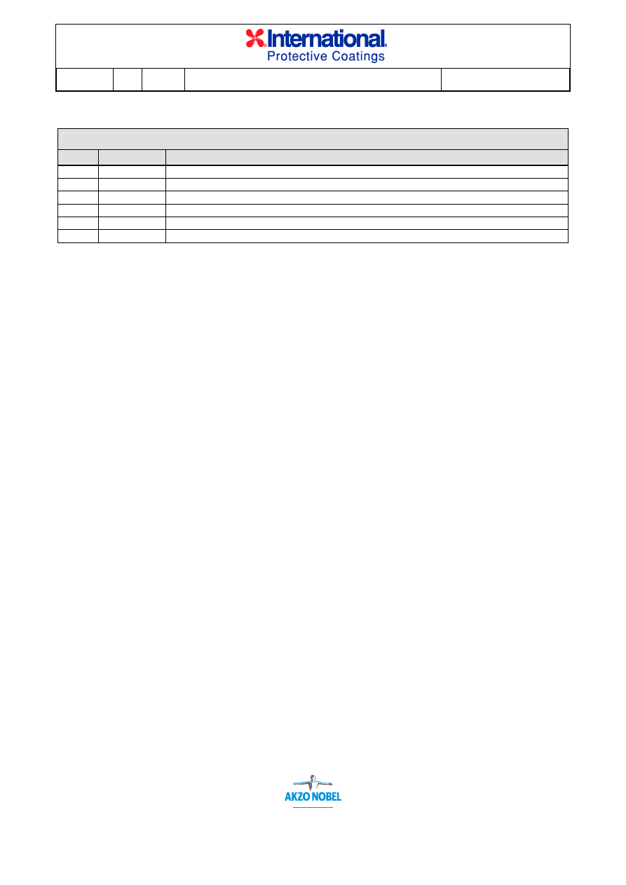
LIST OF CONTENTS
Paragraph
Title
Page
1.0 Introduction
4
2.0 Personnel
and
responsibilities
5
2.1 Project
Manager
5
2.2 Site
Supervisor
5
2.3
Site Quality Control Inspector
5
2.4 Site
Foreman
5
2.5 Application
crew
5
2.6
Typical site organization
6
3.0 Record
keeping
6
4.0 Operating
procedures
7
4.1
Scope of work
7
4.2 Sample
preparation
7
4.3 Work
start-up
7
4.4 Environmental
conditions
7
4.5 Pin
installation
8
4.6 Substrate
preparation
8
4.7 Priming
procedure
8
4.8 Meshing
8
4.9 Masking
8
4.10 Storage
conditions
9
4.11 Solvented
application
9
4.12 Solventless
application
9
4.13 Coating
thickness
10
4.14 Surface
finish
10
4.15 Final
inspection
11
4.16 Repair
procedure
11
5.0
Inspection equipment requirements
11
5.1
Wet film thickness
11
5.2
Dry film thickness
11
5.3
Dry film thickness
11
5.4 Substrate
temperature
11
5.5 Ambient
conditions
12
5.6 Chartek
temperature
12
6.0
Technical service audits
12
Appendices
A
Quality Control Form (example)
B Daily
Log
(example)
C
Daily Equipment Log (example)
D
Technical Service Audit Report Form

ID Rev.
Date
QC MAN GB
3
30/01/06
Chartek
®
QC Manual
Page 13 of 14
©International Paint Limited, 2006
This document and its contents are the copyright of International Paint Limited and may not be reproduced in whole or in part without the express permission of International Paint Limited
1.0 INTRODUCTION
This Manual describes the quality control activities required by International Paint
Ltd. for the application of Chartek fireproofing systems and may be used by
applicators as a guideline on which to base their own quality control procedure.
The manual also includes recommendations for site organisation with descriptions
of relevant key roles and responsibilities. The personnel described are appointed
and employed by the Client or his appointed sub-contractor and not International
Paint Ltd. These are intended as guidelines and are based on our experience of
successful project organisation. Actual site organisation must be defined by those
parties with contractual project authority and responsibilities.
Both fire protection performance and pre-fire durability critically depend on the
correct application of the fireproofing system. The scope of the present Quality
Control Manual is to define the minimum control activities required to verify that the
work is carried out in accordance with the Chartek Application Manual, which should
be referred to for full application instructions.
When required contractually, parts or all of the Quality Control Manual can be
considered an integral part of the project documentation.

ID Rev.
Date
QC MAN GB
3
30/01/06
Chartek
®
QC Manual
Page 13 of 14
©International Paint Limited, 2006
This document and its contents are the copyright of International Paint Limited and may not be reproduced in whole or in part without the express permission of International Paint Limited
2.0
PERSONNEL AND RESPONSIBILITIES
2.1 Project
Manager
The Project Manager is responsible for ensuring the completion of all work in
conformance with contractual requirements. The Project Manager should be in
possession of and fully acquainted with both the relevant Chartek Application
Manual and the present Quality Control Manual. The Project Manager should have
the authority necessary to guarantee the safe and correct management of the site
and productive processes.
2.2 Site
Supervisor
The Site Supervisor is responsible for organising the practical work operations
including daily planning, materials supply and storage and checking on progress.
The Site Supervisor has direct responsibility for the quality of the work carried out
and must therefore have successfully completed a Chartek Training School. Both
the Training School certificate and the relevant Chartek Application Manual should
be in the Site Supervisor’s possession at the work site.
2.3
Site Quality Control Inspector
The Site Quality Control Inspector is responsible for implementing on a daily basis
all the QC checks described in this manual and the project QC plan, where
applicable. The Site Quality Control Inspector must have successfully completed a
Chartek Training School and be in possession of both the Training School certificate
and the relevant Chartek Application Manual at the work site.
The Site QC Inspector is also responsible for the accurate completion and final sign
off of all required QC forms and reports.
Additional responsibilities include ensuring International Paint Ltd. (Fire & Insulation
Products) technical service audit requirements are completed, documented and
available for consultation. This is particularly important with regard to corrective
actions agreed by the contractual parties on non-conformances.
The Site QC Inspector should have the necessary expertise to correctly evaluate
the quality of the work and is responsible for bringing any non-conformances to the
immediate attention of the Project Manager.
NOTE: Depending on the size of the project, one individual may hold more than
one of the positions outlined above.
2.4 Site
Foreman
The Site Foreman’s responsibilities are to carry out the daily supervision of work
teams with the aim of achieving conformance of the application to the relevant
specifications.
ID Rev.
Date
QC MAN GB
3
30/01/06
Chartek
®
QC Manual
Page 13 of 14
©International Paint Limited, 2006
This document and its contents are the copyright of International Paint Limited and may not be reproduced in whole or in part without the express permission of International Paint Limited
2.5 Application
Team
Any workers not in possession of a Chartek Training School certificate shall be
trained in and documented to be capable of the operations required of them.
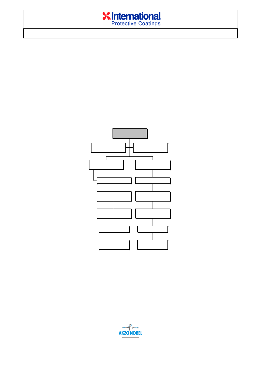
2.6
Typical Site Organisation
The organization of the production sites varies on the basis of different factors
(entity of the contract, location of the site, contractual, organizational and technical
requirements etc.). The following chart shows a typical site organisation.
3.0 RECORD
KEEPING
Records shall be produced and maintained covering the progress of a project. With
good records a reference is available if documentation review is required for any
reason at a later date. Such documentation can help to demonstrate that the work
was carried out in accordance with the specifications.
Generally three types of records are used. The first is a quality control form in which
details of work carried out in a given area are recorded according to when each step
was completed and accepted. The second and third are daily logs to record
personnel, weather conditions, material consumption, surface areas completed and
TYPICAL WORK SITE ORGANISATION
QUALITY CONTROL
INSPECTOR
SITE SUPERVISOR
ASSISTANTS
(GENERAL SERVICES)
MACHINE OPERATOR
ROLLERS
(AND MESH INSTALLERS)
TROWELLERS
(AND MESH INSTALLERS)
SPRAYER
SITE FOREMAN
WORK TEAM "A"
ASSISTANTS
(GENERAL SERVICES)
MACHINE OPERATOR
ROLLERS
(AND MESH INSTALLERS)
TROWELLERS
(AND MESH INSTALLERS)
SPRAYER
SITE FOREMAN
WORK TEAM "B"
PROJECT
MANAGER

ID Rev.
Date
QC MAN GB
3
30/01/06
Chartek
®
QC Manual
Page 13 of 14
©International Paint Limited, 2006
This document and its contents are the copyright of International Paint Limited and may not be reproduced in whole or in part without the express permission of International Paint Limited
equipment details. Examples of each of the three types are shown in Appendices
A, B and C. These examples are provided as guides only and Contractors may
choose to adapt them to each specific contract. Documented quality records are a
requirement of the ISO 9002 quality system standard and International Paint’s
Technical Service Audit Programme.
4.0 OPERATING
PROCEDURES
4.1
Scope of work
The process of Chartek fireproofing application consists of but is not limited to:
surface preparation (normally and ideally by abrasive blast cleaning); priming with
an approved paint product; installation of mesh reinforcement (either International
Paint’s patented HK-1
TM
hybrid carbon/glass mesh or galvanised wire mesh);
masking where necessary; spraying, trowelling and rolling of Chartek; topcoating if
required and demasking.
Two processes of spray application can be used. For all medium to large scale jobs
(i.e. greater than 100m
2
surface area) the recommended process is spraying
Chartek with solventless, plural component airless equipment. For smaller
applications premix solvented application with either single leg airless or modified
conventional airspray equipment may be used. In all cases, the equipment must be
qualified by International Paint Ltd.
4.2 Sample
preparation
Prior to the start up of actual production work an approved sample or a sample area
will be coated with Chartek in accordance with the project specifications. This
sample should be representative of the work to be carried out throughout the
project.
The sample or sample area will then be approved and signed off by the owner’s
representative, applicator’s representative, fabricator’s representative, International
Paint’s Technical Service Engineer and any other party as required by the contract
for the quality of surface finish and conformance with the relevant procedures and
specifications.
4.3 Work
start-up
The Project Manager and Supervisor will obtain a release document from the
owner’s representative for a given area of the structure to start work on.
4.4 Environmental
conditions
Environmental conditions are very important for every aspect of the Chartek
application system. Since Chartek is an epoxy-based material strict adherence to
environmental parameters is required to obtain optimum performance and
application conditions.

ID Rev.
Date
QC MAN GB
3
30/01/06
Chartek
®
QC Manual
Page 13 of 14
©International Paint Limited, 2006
This document and its contents are the copyright of International Paint Limited and may not be reproduced in whole or in part without the express permission of International Paint Limited
Environmental conditions for blasting and priming must be in accordance with the
primer manufacturer’s written instructions. Environmental conditions for the Chartek
system application are outlined in the respective sections of the Application
Manuals for each process. These conditions should be recorded on an hourly basis
since conditions can vary considerably depending on location. Record daily
environmental conditions in the form provided in Appendix B.
4.5 Pin
installation
When applicable (for example for NORSOK referenced projects), pin installation
shall be carried out in accordance with the procedure described in the Chartek
Application Manual.
A 20-pin bend test shall be carried out and documented daily before production
begins. The 20 pins shall be bent from 90º to 45º and back with respect to the
surface plane. If more than one pin fails, the test will be considered a failure and
another 20 pins shall be welded using different machine settings and tested. If the
second test fails, advice should be sought from the welder manufacturer or an
International Paint Ltd, Technical Service Engineer. Pins that have not failed in the
failed test do not have to be removed. Once a successful test has been carried out
and documented production pinning can begin. If the welding equipment is
modified during the day an additional test may be required to verify that the settings
are still valid.
4.6 Substrate
preparation
Substrate preparation shall be carried out in accordance with the procedures
described in the Chartek Application Manual.
The cleaning grade (for example, Sa 2 ½ according to ISO 8501-1) and blast profile
shall be documented and accepted prior to priming as per Appendices A and B.
If the Chartek applicator does not actually perform the blasting and priming, the
applicator is responsible for verifying the conformance of surface preparation and
primer with the Chartek Application Manual requirements by means of either
suitable QC documentation or first hand testing and inspection.
4.7 Priming
procedure
Priming of the substrate shall be carried out in accordance with the procedures
described in the Chartek Application Manual.
Only primers on the “Chartek Fireproofing Qualified Primer Systems” list may be
used, unless written authorisation from International Paint is obtained for another
primer system.
Documentation for the primer system shall consist of primer name, type and applied
thickness on a daily basis as per Appendices B and C.

ID Rev.
Date
QC MAN GB
3
30/01/06
Chartek
®
QC Manual
Page 13 of 14
©International Paint Limited, 2006
This document and its contents are the copyright of International Paint Limited and may not be reproduced in whole or in part without the express permission of International Paint Limited
4.8 Meshing
Mesh reinforcement shall be installed in accordance with the procedures described
in the relevant Chartek Application Manual.
Documentation of the mesh system used shall include mesh type, size, attachment
means and standoffs (not applicable for HK-1
TM
hybrid carbon/glass mesh).
4.9 Masking
Any surfaces or equipment in the spraying areas that do not require fireproofing
must be masked off using tarpaulins or equivalent.
Regardless of the structural configuration being protected, overspray is always a
concern. Quality control includes the aesthetics of the finish and protection of areas
outside the termination points of the applied Chartek.
4.10 Storage
conditions
Chartek storage conditions are outlined in the Application Manual, which contains
instructions for long-term storage, preparation storage for premix solvented and
plural component solventless spray application.
The storage requirements are specifically designed to optimise material
performance and ease of application.
Daily temperature recordings shall be documented for each applicable storage site
and should include both ambient and actual core sample temperatures as per
Appendix B.
4.11 Solvented
application
Solvented application shall be carried out in accordance with the procedures
outlined in the Chartek Application Manual.
Documentation shall include but not be limited to: environmental conditions;
equipment type; material temperature; solvent type and amount; coating thickness;
location of area sprayed; material batch numbers (all as per Appendices A, B and
C).
4.12 Solventless
application
Solventless application shall be carried out in accordance with the procedures
outlined in the Chartek Application Manual.
Documentation shall include but not be limited to: environmental conditions;
equipment type; material temperatures; tank temperatures; heater temperatures;
line temperature; gun exit temperature; spray pressures for each component;
coating thickness; location of area sprayed; material batch numbers (all as per
Appendices A, B and C).

ID Rev.
Date
QC MAN GB
3
30/01/06
Chartek
®
QC Manual
Page 13 of 14
©International Paint Limited, 2006
This document and its contents are the copyright of International Paint Limited and may not be reproduced in whole or in part without the express permission of International Paint Limited
With solventless hot spray equipment, mixing of the two components is
automatically achieved at the correct ratio by the displacement pumps.
Furthermore, solventless spraying reduces curing times and improves the overall
efficiency and quality of the Chartek application. For these reasons, International
Paint strongly recommends the use of this type of equipment. Although most
machines incorporate off-ratio detection devices, actual ratio checks by weight
should be taken before start-up of spraying.
Reference should be made to the ratio parameters included in the relevant Chartek
Application Manual. In addition to the ratio checks by weight, constant checking of
the displacement pump pressure gauges and the colour of the mixed Chartek
should be carried out by the sprayer and machine operator respectively. Ratio
checks should be made at the commencement of each work shift or more frequently
as demanded by the project application schedule.
4.13 Coating
thickness
The correct measurement of the fireproofing system thickness is critical to
guaranteeing conformance with the project specification and the following criteria
should be strictly adhered to.
A. Method for measuring wet Chartek thickness
The recommended method of measuring wet thickness is to use a pre-cut bridge
gauge having a width of approximately 25mm (typically made from a putty knife).
Notch or pin gauges are not acceptable because they limit the measurement to one
point. The gauge should just touch the rolled Chartek surface. We strongly
recommend the continuous use of the bridge gauge by all members of the
application team from the sprayer to the troweller to the roller. In this way you can
be assured of reaching the design thickness over the whole surface.
B. Method of measuring dry Chartek thickness
Dry thickness can be measured by either of the following methods:
¾ drilling a small hole approximately 2mm in diameter and checking the Chartek
thickness with a depth gauge (care must be taken not to damage the substrate
and to refill the holes with Chartek as soon as possible);
¾
using an electromagnetic thickness gauge (care must be taken to correctly
calibrate the gauge immediately before taking any readings). This method
cannot be used if the Chartek is reinforced with wire mesh.
NB: Chartek fireproofing ratings that are certified by Approval Authorities generally
require that the specified passive fireproofing thickness is to be the minimum
application thickness. It is recognized, however, that the applied Chartek layer will
never be perfectly even and that areas of lower than design thickness (“valleys”) are
compensated by areas of higher than design thickness (“peaks”). Unless specifically
stated otherwise in the project documentation, the minimum acceptable thickness at
any point shall not be less than 85% of the design thickness up to a maximum of

ID Rev.
Date
QC MAN GB
3
30/01/06
Chartek
®
QC Manual
Page 13 of 14
©International Paint Limited, 2006
This document and its contents are the copyright of International Paint Limited and may not be reproduced in whole or in part without the express permission of International Paint Limited
1.5mm less than the design thickness. In other words, for thicknesses up to and
including 10mm the minimum allowable thickness is 85% of the design thickness.
For thicknesses above 10mm the minimum allowable thickness is the design
thickness less 1.5mm.
Thickness readings should be accurately recorded as per Appendices A and B.
4.14 Surface
finish
The quality of surface finish should be agreed on by all the parties involved before
project start-up. Surface finish throughout the project is rated as acceptable or
unacceptable as compared to the sample reference.
Although surface finish may not hinder the fire performance of Chartek
it leaves a
lasting impression of the quality of both material and applicator. The highest quality
goes into Chartek from manufacturing to application in accordance with ISO 9000
standards. Therefore, reasonable care should be taken to achieve the highest
standard possible and due consideration given to specific requirements stated in
project documentation.
4.15 Final
inspection
After all QC documentation is submitted, final inspection will be carried out by the
owner’s representative, applicator’s representative, fabricator’s representative,
International Paint’s Technical Service Engineer and any other party as required by
the contract. Areas will then be signed off for acceptance or repairs noted and
carried out as per Appendices A and B.
A 100% visual inspection should be performed to ensure there is no exposed mesh,
debonding at terminations or bubbles below the surface layer of Chartek.
Physical inspection consists of measurement of dry film thickness of the Chartek
system and tapping to detect possible hollow areas or delamination between
sprayed layers of Chartek not easily visible.
4.16 Repair
procedure
Repair procedures are described in the Chartek Application Manual.
The same tests and inspections described above and summarised in the
Appendices A, B and C apply equally to repair applications.
For unusual repair situations contact International Paint Technical Service for
written instructions.

ID Rev.
Date
QC MAN GB
3
30/01/06
Chartek
®
QC Manual
Page 13 of 14
©International Paint Limited, 2006
This document and its contents are the copyright of International Paint Limited and may not be reproduced in whole or in part without the express permission of International Paint Limited
5.0
INSPECTION EQUIPMENT REQUIREMENTS
5.1
Wet film thickness (bridge gauge)
A bridge gauge is used to check wet Chartek thickness during application. It is
easily made by cutting a 25mm wide piece of metal to the desired thickness and
continually sticking it into the Chartek while wet. The gauge should be used by all
members of the application team (sprayer, troweller and roller).
5.2
Dry film thickness (mechanical depth micrometer)
A mechanical depth micrometer is required to inspect cured Chartek for thickness
measurements. It is recommended that a gauge with a narrow barrel is utilised with
a range from 0–100mm.
5.3
Dry film thickness (electronic thickness gauge)
This type of gauge is used to measure the thickness of dry coatings on steel
substrates. It can be used to measure both the primer and Chartek dry film
thickness (but not if metal mesh is used as the reinforcement system as this will
give erroneous readings with the electro-magnetic type gauge). Care should be
taken to calibrate the instrument on a polished steel plate with calibrated shims of
similar thickness to the coating to be measured before each use.
5.4
Substrate temperature (surface thermometer)
A thermometer should be used to measure the surface temperature of the substrate
immediately before Chartek is applied. It should be calibrated to the manufacturer’s
specification and should have a range of 0-100ºC.
5.5
Ambient conditions (sling psychrometer, hygrometer, air thermometer)
Reliable intrumentation should be used to record air temperature and relative
humidity. We recommend the use of a sling psychrometer as it is a simple but
reliable and robust instrument. It consists of two thermometers in a frame one of
which has a wet bulb and the other a dry bulb. The wet bulb gauze draws
demineralised water during whirling and the temperature of the evaporating water is
read off the wet bulb thermometer scale. The dry bulb measures air temperature.
Whirling should continue for at least 60 seconds before first readings are taken.
Acceptable readings are those taken at 20-30 second intervals after the first check.
The wet and dry readings are then read off a circular or slide rule guide to give the
relative humidity value. The dew point temperature can then be calculated in
relation to air temperature and relative humidity.
Environmental parameters are described in the Chartek Application Manual but as a
general rule the air temperature should always be above 10ºC, relative humidity
should be less than 85% and the substrate temperature should be at least 3ºC
above the dew point temperature during application and for a period of 2 hours after
application.

ID Rev.
Date
QC MAN GB
3
30/01/06
Chartek
®
QC Manual
Page 13 of 14
©International Paint Limited, 2006
This document and its contents are the copyright of International Paint Limited and may not be reproduced in whole or in part without the express permission of International Paint Limited
5.6
Chartek temperature (digital thermometer/bi-metal thermometer)
These thermometers are used to record Chartek temperatures during storage and
application. They should be calibrated to the manufacturer’s specification.
Recommended Chartek temperatures are detailed in the Application Manual.
6.0
TECHNICAL SERVICE AUDITS
In addition to the forms and records produced by the qualified applicator, copies of
the International Paint Technical Service Audit Report and Non-Conformance
Report (if raised) shall also be maintained. These reports will be supplied by an
International Paint Technical Service Engineer.
The Technical Service Engineer and the applicator’s QA/QC representative will sign
each report generated. Copies of reports will be distributed by the Technical Service
Engineer to the applicator’s QA/QC representative on site and the owner’s
representative at the end of each Technical Service Engineer’s visit. Additional
copies will be distributed to respective agencies as required by the project
specifications.
The maintenance of these records is important in that a history of audits is
documented for each project. Follow-up audits may require reference to verify that
requested remedial action has been successfully completed, or situations may arise
where past audut history requires review.
Reference Appendix D for instructions on how to complete the Technical Service
Audit Report.
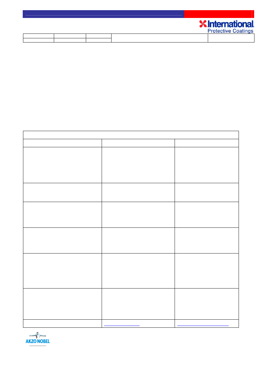
©International Paint Limited, 2005
This document and its contents are the copyright of International Paint Limited and may not be reproduced in whole or in part without the express permission of International Paint Limited
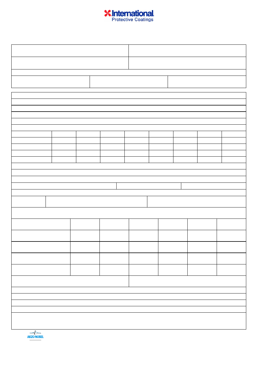
CHARTEK
®
FIREPROOFING – AREA QUALITY CONTROL REPORT
Project:
Owner:
Owner’s representative:
Applicator’s representative:
Area identification: see attached drawing
Report Nº: XXX - A
Date:
Prepared by:
OPERATION
DATE
Nº TEST ACTIVITY
(see QCP nº XXX)
SIGNATURE
SITE MANAGER/QC
COMMENTS
BLAST CLEANING-PRIMER-MASKING
Blast cleaning-primer
Acceptance of
surfaces
Masking
Sample area
CHARTEK APPLICATION-MESHING
1st Coat
Mesh installation
2nd Coat
TOPCOAT
1st Coat
2nd Coat
NOTES
AREA COMPLETE
Applicator:
Signature:
Name:
Owner:
Signature:
Name:
APPENDIX A
©International Paint Limited, 2006
This document and its contents are the copyright of International Paint Limited and may not be reproduced in whole or in part without the express permission of International Paint Limited
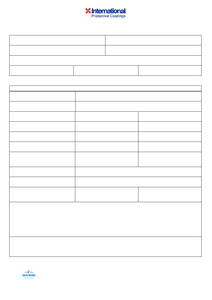
CHARTEK
®
FIREPROOFING DAILY LOG
Project:
Owner:
Owner’s representative:
Applicator’s representative:
Area identification: see attached drawing
Report Nº: XXX - B
Date:
Prepared by:
PERSONNEL
Site Manager:
Site QA/QC Manager:
Sprayers-trowellers:
Owner’s QC Inspector:
ENVIRONMENTAL CONDITIONS (to be recorded every hour)
Time
Ambient temp.
Relative
humidity
Dew point
Substrate
temp.
MESH INSTALLATION
Mesh installed (type and surface area in m
2
):
Edge mesh (Charlok) installed (linear metres):
CHARTEK STORAGE TEMPERATURE
Part A
Part B
CHARTEK APPLICATION
Ratio
(% in weight)
A.M. Part A Part B
P.M. Part A Part B
SPRAY EQUIPMENT ID (type and serial number):
ID areas coated
(if different from drawing)
Specified thickness (mm)
Thickness applied to date
Thickness applied today
Surface area coated (m
2
)
Chartek
quantity used (no. of kits)
Part A Part B
Solvent used :
Type Quantity (lt.)
CHARTEK BATCH NUMBERS
Part A:
Part B:
NOTES
Signature Site Manager-Site QA/QC Manager:
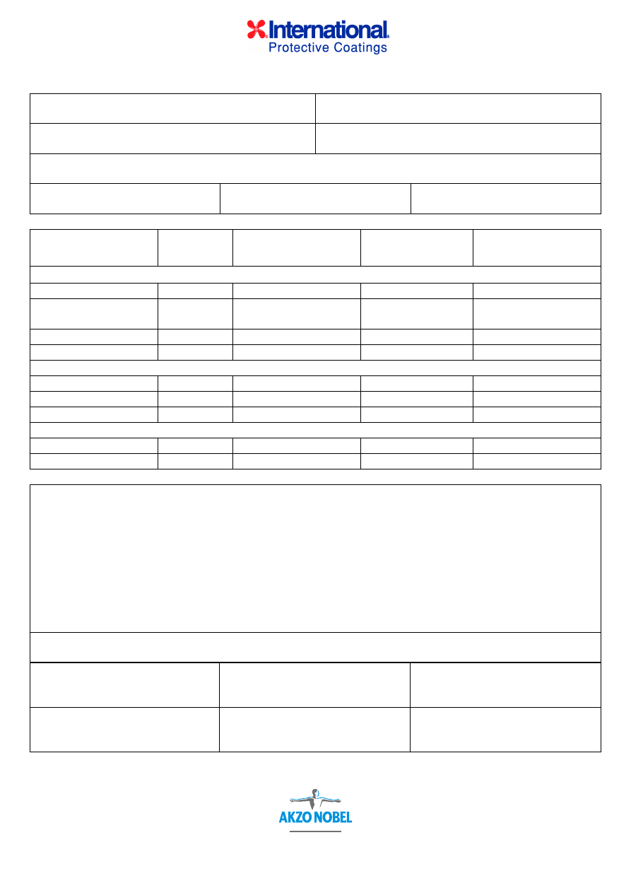
APPENDIX B
©International Paint Limited, 2006
This document and its contents are the copyright of International Paint Limited and may not be reproduced in whole or in part without the express permission of International Paint Limited
CHARTEK
®
FIREPROOFING EQUIPMENT QUALITY CONTROL REPORT
Project:
Owner:
Owner’s representative:
Applicator’s representative:
Area identification: see attached drawing
Report Nº: XXX - C
Date:
Prepared by:
PLURAL COMPONENT SYSTEM
Machine type
Hose length
Preloading Chartek temperature
Part A:
Part B:
Tank temperatures
Part A:
Part B:
Tank pressures
Part A:
Part B:
In-line heater temperatures
Part A:
Part B:
Displacement pump pressures
(at cylinder exit)
Part A:
Part B:
Line heat
Gun exit temperature
Spray gun
Tip size (1/1000”):
Fan size (mm):
NOTES
Signature Site Manager-Site QA/QC Manager:
APPENDIX C

©International Paint Limited, 2006
This document and its contents are the copyright of International Paint Limited and may not be reproduced in whole or in part without the express permission of International Paint Limited
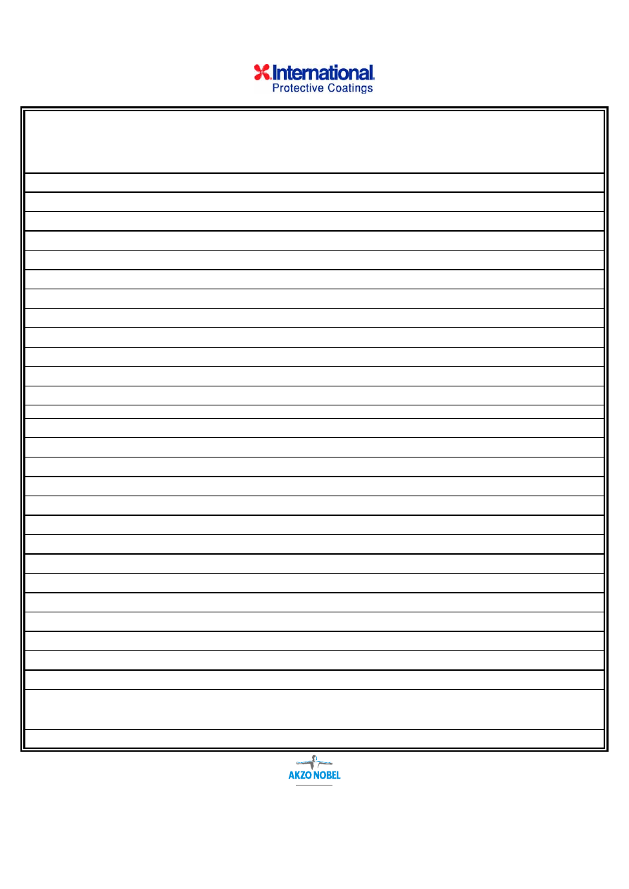
APPENDIX D
INTERNATIONAL PAINT TECHNICAL SERVICE AUDIT REPORT
Purpose
The Technical Service Audit Report is a site-generated report prepared
by an IPL Technical Service Engineer. It serves one or more of the
following purposes:
1. To demonstrate that IPL monitors on an ongoing basis the application
of Chartek
®
fireproofing and, where appropriate, to meet contractual
requirements for such monitoring activity.
2. To record specific details regarding Chartek fireproofing projects.
3. To generate a database for non-mandatory procedures and
processes.
4. To record application details that were found to be in conformance
with project and/or IPL requirements during the audit by the IPL
Technical Service Engineer.
5. To identify non-conformances with project and/or IPL recommended
procedures and requirements.
6. To measure the level of quality control utilised by Applicators.
Procedure
A major responsibility of IPL Technical Service Engineers is to monitor
the application of Chartek fireproofing. On a visit to an application site,
the Technical Service Engineer will audit procedures/practices used prior
to his visit to ensure conformance with project and/or IPL recommended
procedures and requirements. These steps may include, but are not
limited to, core drilling of previously applied Chartek to check for
thickness, the presence of uncured material, contaminated interfaces
between Chartek layers, the required and proper installation of mesh,
availability of inspection/application logs, primer thickness requirements,
and other steps.
Though the bulk of his time at a site will be spent with Applicator
personnel, upon arrival, the IPL Technical Service Engineer will advise
the Constructor’s/Fabricator’s representative and the Client
representative that he is present, how long he expects to be on site, and
the purpose of his visit. He will also indicate that before leaving he will
complete a Technical Service Audit Report and that a copy would be
available for both the Constructor/Fabricator and the Client. If either, or
both, decline to receive copies, the IPL Technical Service Engineer will
so indicate on the report.

©International Paint Limited, 2006
This document and its contents are the copyright of International Paint Limited and may not be reproduced in whole or in part without the express permission of International Paint Limited
Completing
theTechnical
Service Audit
Form
Prior to departure from the site, the IPL Technical Service Engineer will
provide a copy of the completed and signed-off Audit Report to the
Applicator’s site and Quality Control Supervisors, as well as the
Constructor’s/Fabricator’s and Client’s representatives, as required.
Distribution to other recipients will be made as soon as conveniently
possible, but no later than five days from departure from the site.
The key for completing the Technical Service Audit Report is as follows:
1.
Report Ref. (number) - assigned by Technical Service personnel.
The report number will consist of three alphabetic letters which
identify the project, followed by three numbers which are used to
indicate the sequential number of the report for the project.
2. Report
By – the Technical Service Engineer’s name.
3. Date – the date/dates of the visit.
4.
The Project Name – typically the owner’s/operator’s name followed
by the unit’s designation (MDI, Benzene/Styrene, etc.) or module
description (number and/or type).
5. Construction/Fabricator- self explanatory.
6.
Constructor/Fabricator Representative – the person from the
Constructor/Fabricator responsible for the fireproofing installation.
The person may be an inspector, painting/fireproofing supervisor,
engineer, or have another title. If the responsible individual is not
available or declines to receive a copy of the Audit Report,
“Unavailable” or “Declines Copy” should be noted in the box.
7. Client’s
Inspector – Owner’s/Operator’s representative.
8. Applicator – the name of the application contractor.
9. Site
Supervisor – the Applicator’s senior employee on the site.
10.
Site QA/QC Supervision – the Applicator’s QA/QC employee on
the site.
11. Other
– other key Applicator employees at the site.
12. Other – other Applicator QA/QC employees on site.
13.
Plural Solvent Free Airless Machine – the quantity and
manufacturer of such machines in operation.
14.
Single Leg Modified Airless Machine – the quantity of machines,
air motor size and foot ratio (68-74:1).
15. Temperature – the ambient temperature range.

©International Paint Limited, 2006
This document and its contents are the copyright of International Paint Limited and may not be reproduced in whole or in part without the express permission of International Paint Limited
Completing the
Technical
Service Audit
Form
16. Humidity – the relative humidity range.
17.
Steel Temperature – the temperature of the steel being
fireproofed.
18.
Condition of Storage of Chartek Fireproofing – the conditions of
storage should be noted.
19.
Area Quality Control Reports used – if area quality control reports
are not being used, indicate the nature of the documentation the
Applicator is using to prove he is complying with the project
specification.
20.
Area(s) Audited - the areas audited during the visit. It could be
identified by drawings attached to the Audit Report, truss row
designation, elevations, etc.
21.
Location of Sample Area – if at all possible, the sample area must
be part of the structure being fireproofed, not a separate
construction.
22. Chartek
Thickness – measured thickness of the sample area.
23. Accepted
By – self explanatory.
24.
Finish or Sample Area – an objective comment on the acceptability
of the surface finish and whether it is representative of what can be
achieved on the project.
25.
Mesh Attachment Means – pins.
26.
If Pins, When Installed – after or before blasting.
27.
Weld Integrity Verification – logs or actual tests performed by IPL
Technical Service Engineer or in his presence by Applicator
personnel.
28.
Profile or Blast Finish – Swedish Standard, NACE, or SSPC
designation or, alternatively, profile depth.
29. Performed
By – the firm who prepared the substrate.
30.
Verification – the means by which the profile or blast finish is
verified. Verification may take the form of constructor or applicator
logs, imprints, etc.
31. Primer
Material
– the brand name and type of the primer materials.

©International Paint Limited, 2006
This document and its contents are the copyright of International Paint Limited and may not be reproduced in whole or in part without the express permission of International Paint Limited
Completing the
Technical
Service Audit
Form
32.
Verification – the means of knowing that the materials used are in fact
what is reported. It can be logs, primer supplier certification, cans on
site, etc.
33.
Primer Thickness – the range of thicknesses and the appropriate
number of measurements taken.
34. Verification
– the individual who made the measurements.
35.
Mesh Coverage and Stand-offs – self explanatory.
36.
Conditions of Surface when Chartek is Applied – surfaces must be
clean, dry and free of contaminants. Recommended coating intervals
must be observed, or surfaces must be reprepared.
37.
Solvent Used – solvents used for both mixing (if conventional
equipment is used) and rolling, if different.
38.
Machine – indicates machine number. If operation of more than three
machines is audited, a second form is to be used.
39.
Ratio Check – the percentage of each part is to be listed based on
actual measurements or review of ratio logs.
40.
As 39 above.
41. Batch
Nos. – self explanatory.
42. Batch
Nos.
– self explanatory.
43. Tank
Temperatures – the temperature setting in the hold tanks.
44.
In-Line Heater Temperatures – self explanatory.
45. Delivery
Pressure – the pressure developed at the pump foot.
46. Line
Heat – the temperature setting for the delivery hose lines.
47.
Gun Exit Temp. – the temperature of the product exiting the gun or
the in-line mixer.
48. Tip
Size – the tip designation.
49.
Fan Dimension – the shape of the fan, the fan width and the distance
of the gun from the object.
50. Spray
Line
Length – self explanatory.
51.
Initial or Intermediate Coats – any surface anomalies which, if not
corrected, will cause unacceptable surface finish conditions should be
noted.

©International Paint Limited, 2006
This document and its contents are the copyright of International Paint Limited and may not be reproduced in whole or in part without the express permission of International Paint Limited
Completing the
Technical
Service Audit
Form
52.
Surface Finish – in conformance with finish agreed by all parties at
commencement of project.
53.
Thickness Measurement Specification – thickness compared to the
actual measured thickness.
54.
As 53 above.
55. Topcoat
Material – the brand name and type of topcoat.
56.
Topcoat Thickness – the dry film thickness of the topcoat or recorded
usage rate (m
2
/l or ft
2
/gal).
57.
Safety Observations – any obviously unsafe practices being used
should be noted. Lack of eye protection, safety shoes, skin
protection and other personnel protection equipment, improper use of
solvent or equipment, etc. should be noted.
58.
Application Manual On-Site – self explanatory.
59.
QC Manual On-Site – self explanatory.
60.
Observations – comments and suggestions regarding procedures
used and suggested alternatives which may be to the benefit of the
Applicator or ultimately the Client. Observations can include
practices or procedures which, if not corrected prior to completion of
work in a specific area, may result in a discrepancy. Observations
falling into this latter category will be reported in a separate Technical
Service Non-Conformance Report.
61.
Discrepancies – a brief description of the discrepancy and a
reference to the Technical Service Non-Conformance Report
Number.
62.
Comments – suggestions which may result in productivity, surface
finish improvements, or general notes.
63.
Discrepancies advised to Site Manager/Supervisor, Yes/No – circle
as applicable.
64.
Indicate (circle as applicable) if an TSNR was generated and provide
number(s).
65.
Sign-offs for report.
©International Paint Limited, 2005
This document and its contents are the copyright of International Paint Limited and may not be reproduced in whole or in part without the express permission of International Paint Limited
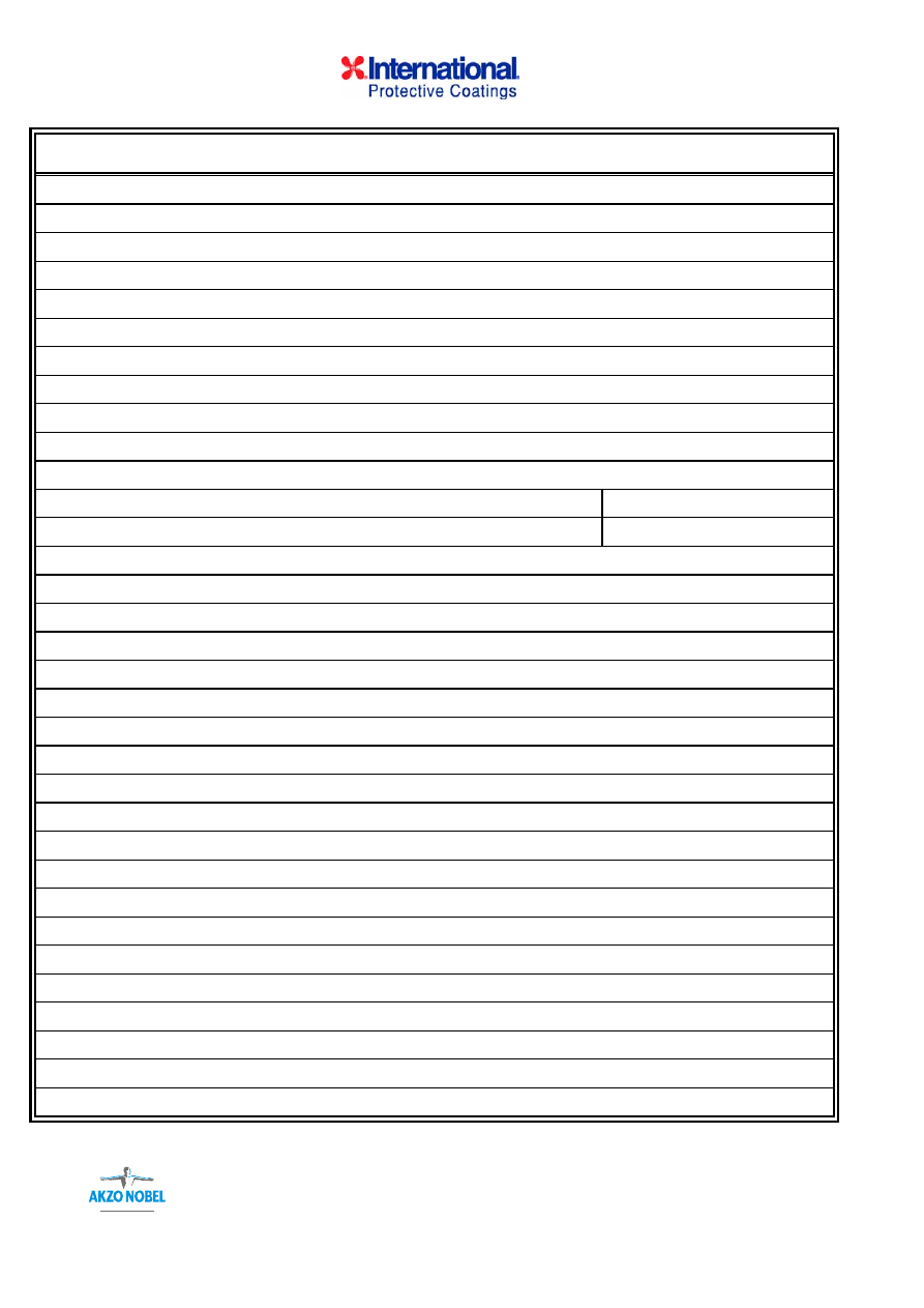
22
TECHNICAL SERVICE AUDIT REPORT
REPORT REF.: (1)
REPORT BY : (2)
CHARTEK
®
:
4 7 1709
8
DATE
:
(3)
PROJECT: (4)
GENERAL CONTRACTOR/FABRICATOR:
(5)
GENERAL CONTRACTOR/FABRICATOR INSPECTOR:
(6)
CLIENT'S INSPECTOR:
(7)
APPLICATOR:
(8)
KEY APPLICATOR PERSONNEL AT SITE:
SITE SUPERVISOR:
(9)
SITE QA/QC SUPERVISOR: (10)
OTHERS:
(11)
OTHERS:
(12)
SPRAY EQUIPMENT AT SITE:
AIRLESS-SOLVENTLESS SPRAY MACHINE: (13)
CONVENTIONAL
PUMP: (14)
IS SPRAY BEING DONE INSIDE?
YES
NO
WEATHER:
TEMPERATURE:
(15)
HUMIDITY:
(16)
STEEL TEMPERATURE:
(17)
CONDITIONS OF STORAGE OF CHARTEK FIREPROOFING:
(18)
AREA QUALITY CONTROL REPORTS BEING USED?
YES
(19)
NO
IF NO, PROVIDE DETAIL:
AREA(S) AUDITED:
(20)
SAMPLE AREA:
LOCATION OF SAMPLE AREA:
(21)
CHARTEK THICKNESS:
(22)
ACCEPTED BY:
(23)
OWNER CONSTRUCTOR (Circle as appropriate)
FINISH OF SAMPLE AREA:
(24)
©International Paint Limited, 2006
This document and its contents are the copyright of International Paint Limited and may not be reproduced in whole or in part without the express permission of International Paint Limited
TECHNICAL SERVICE AUDIT REPORT
MESH ATTACHMENT:
MESH ATTACHMENT MEANS:
(25)
IF PINS, WHEN INSTALLED?
(26)
WELD INTEGRITY VERIFICATION:
(27)
SUBSTRATE PREPARATION:
STANDARD:
(28)
PROFILE:
(28)
PERFORMED BY:
(29)
VERIFICATION: (29)
PRIMER:
PRIMER MATERIALS:
(31)
VERIFICATION: (32)
PRIMER THICKNESS:
(33)
VERIFICATION: (34)
MESH COVERAGE AND STAND-OFFS:
(35)
CONDITION OF SURFACE WHEN CHARTEK IS APPLIED:
(36)
SOLVENT USED:
(37)
©International Paint Limited, 2006
This document and its contents are the copyright of International Paint Limited and may not be reproduced in whole or in part without the express permission of International Paint Limited
TECHNICAL SERVICE AUDIT REPORT
SPRAYING:
MACHINE (38)
MACHINE (38)
MACHINE (38)
Part A
Part B
Part A
Part B
Part A
Part B
RATIO CHECK:
(39) (40) (39) (40) (39) (40)
BATCH NOS.:
(41) (42) (41) (42) (41) (42)
TANK TEMP.:
(43) (43) (43) (43) (43) (43)
IN-LINE HEATER TEMP.:
(44) (44) (44) (44) (44) (44)
DELIVERY PRESSURE:
(45) (45) (45) (45) (45) (45)
LINE HEAT:
(46) (46) (46)
GUN EXIT TEMP.:
(47) (47) (47)
TIP SIZE:
(48) (48) (48)
FAN DIMENSION:
(49) (49) (49)
SPRAY LINE LENGTH:
(50) (50) (50)
INITIAL OR INTERMEDIATE COATS: (51)
SURFACE FINISH:
(52)
THICKNESS MEASUREMENTS:
SPECIFICATION: (53)
MEASURED:
(54)
TOPCOAT:
MATERIAL:
(55)
THICKNESS: (56)
SAFETY OBSERVATIONS:
(57)
CURRENT APPLICATION MANUAL
YES
NO (58)
QC MANUAL ON SITE:
YES
NO (59)
ON
SITE:
(Circle
One)
(Circle
One)
©International Paint Limited, 2006
This document and its contents are the copyright of International Paint Limited and may not be reproduced in whole or in part without the express permission of International Paint Limited
OBSERVATIONS: (60)
DISCREPANCIES: (61)
COMMENTS:
(62)
WERE DISCREPANCIES BROUGHT TO THE ATTENTION OF
YES
NO
APPLICATOR'S SITE MANAGER/SUPERVISOR?
(63)
(Circle One)
WAS
AN
TSNR
RAISED?
(64)
YES
NO
NUMBER(S):
IPL REP.:
(65)
APPLICATOR REP.:
NAME:
NAME:
SIGNATURE:
SIGNATURE:
©International Paint Limited, 2006
This document and its contents are the copyright of International Paint Limited and may not be reproduced in whole or in part without the express permission of International Paint Limited
TECHNICAL SERVICE NON-CONFORMANCE REPORT
TSNR
No:
Page 1 of 2
REF. AUDIT REPORT No:
TSNR ISSUED TO:
DATE:
PROJECT: LOCATION:
PROJECT
MANAGER:
TSNR ORIGINATOR:
TSNR CLASSIFICATION
TSNR DELIVERED TO:
[ ] Class I [ ] Class II [ } Observation
Date:
ISSUED TO FABRICATOR/CONSTRUCTOR: Yes/No
NAME:
REFERENCE DOCUMENT(S):
DESCRIPTION OF DISCREPANCY/OBSERVATION
INTERNATIONAL PAINT’S RECOMMENDATIONS
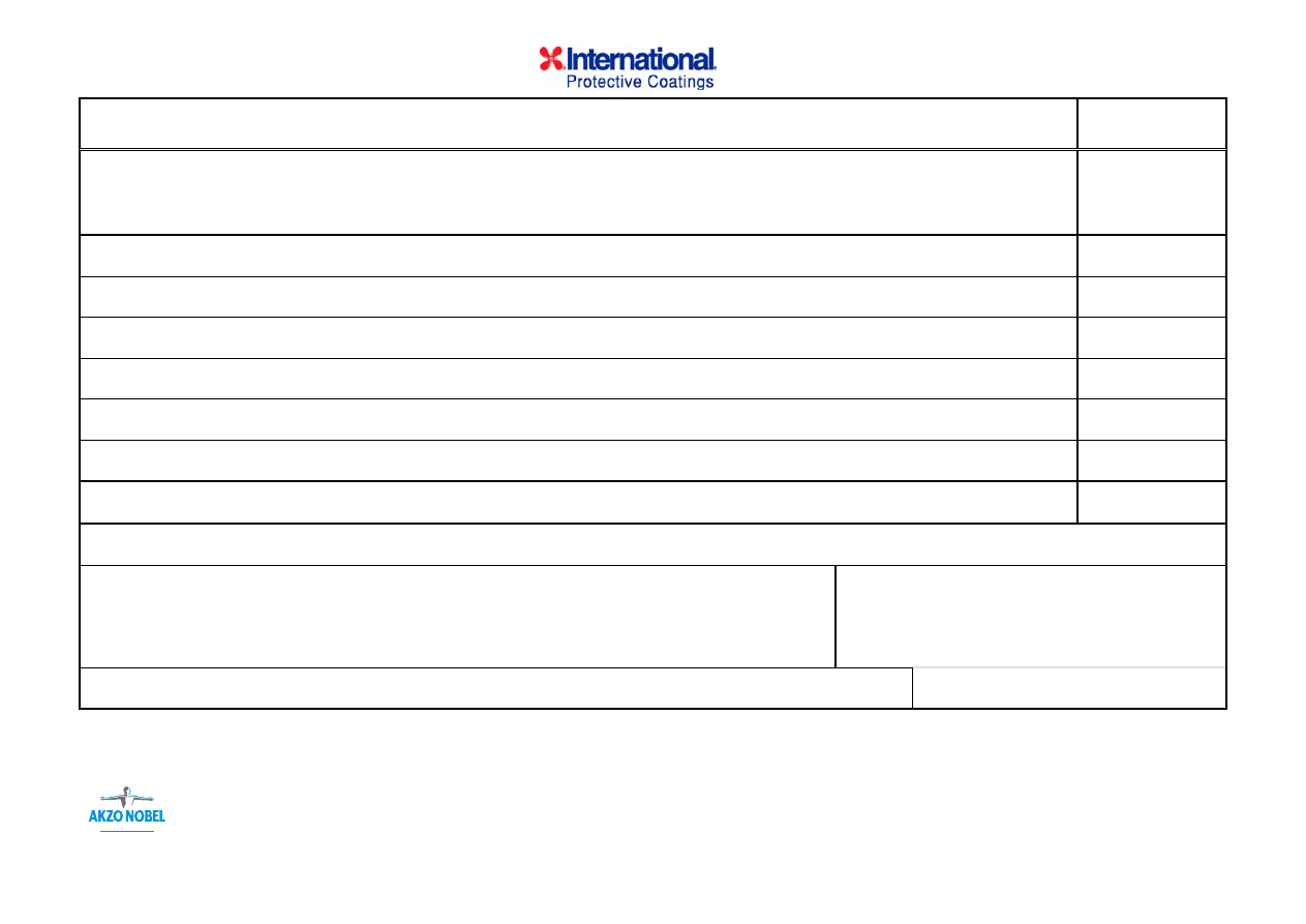
©International Paint Limited, 2006
This document and its contents are the copyright of International Paint Limited and may not be reproduced in whole or in part without the express permission of International Paint Limited
TECHNICAL SERVICE NON-CONFORMANCE REPORT
Page 2 of 2
APPLICATOR PROPOSED CORRECTIVE ACTION
SCHEDULED
COMPLETION
DATE
INDIVIDUAL RESPONSIBLE FOR C/A:
APPROVAL OF PROPOSED CORRECTIVE ACTION
APPLICATOR REP::
FABRICATOR/CONSTRUCTOR REP::
INTERNATIONAL TECHNICAL SERVICE
REP:
DATE:
DATE:
DATE:
Wyszukiwarka
Podobne podstrony:
Matw 05 30 10 06
Krzepnięcie - 30.10.06, 30
morska 30-11-06 (BIAŁA FLOTA), TURYSTYKA MORSKA
zarzadzanie logistyczne 30 04 06, zarządzanie logistyką
kol 30 10 06, 2004-01-05
plan pracy - taktyka - maskowanie bezpośrenie w działaniu w nocy 30.08.06, Taktyka
HLP - oświecenie - opracowania lektur, 30. Jan Potocki, Rękopis znaleziony w Saragossie. DZIEŃ 43, 4
kalkulator zast infy 30,11,06
Kalkulator zast infy 30,11,06
Leslie Charteris The Saint 30 The Saint On the Spanish Main
2001 06 30
test b - odpowiedzi ostateczne 30[1].06.07, Fizjologia Pracy Prof.Łaszczyca
Psalm 30, Komentarze do Psalmów-Papież Jan Paweł II,Benedykt XVI
30 06
06 MANUAL TRANSAXLE (C153)(1)
PN EN 12697 7 2006 06 30
DGP 2014 06 30 rachunkowosc i audyt
więcej podobnych podstron