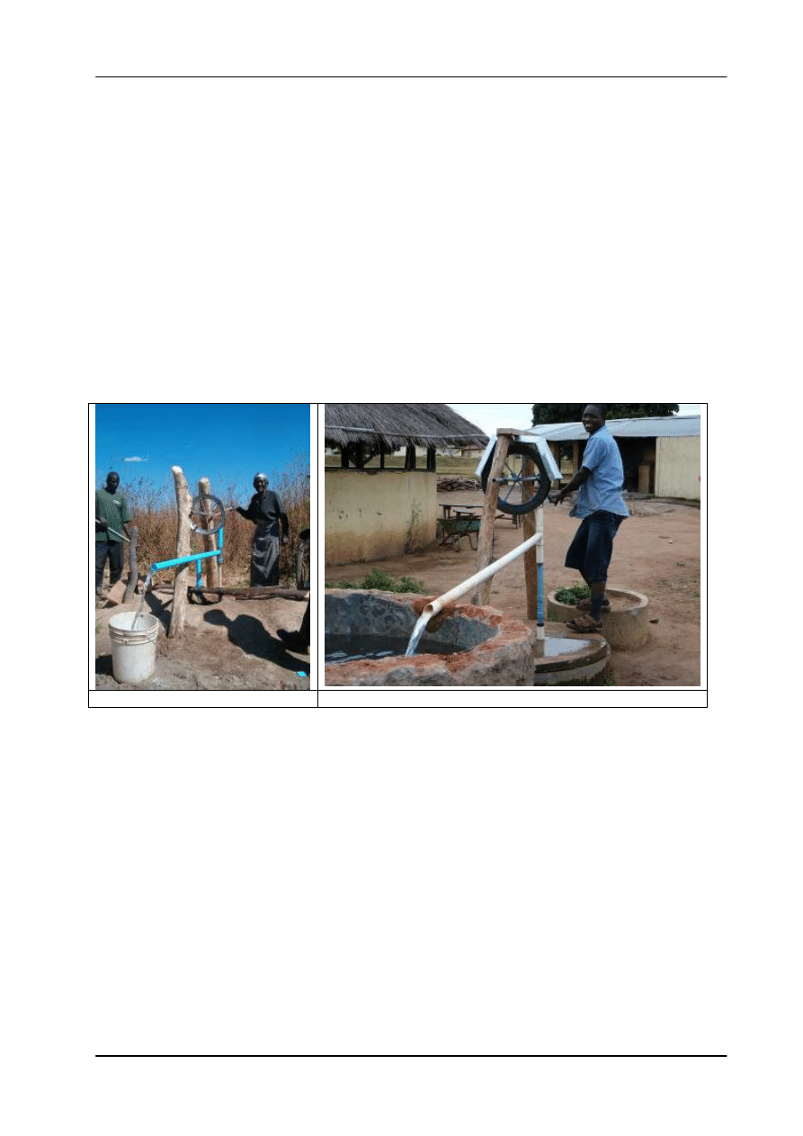
Training Manual PI-Model Rope Pump, Module 1, Production
Arrakis
1
Training Manual
Hand Rope Pump,
P – Model
Module 1: Production
June 2006, Chibombo, Zambia
July 2006, Chimoio, Mozambique
Arrakis
September 2006

Training Manual PI-model Rope Pump, Module 1 Production
2
Arrakis
Table of Contents
1
Introduction.............................................................................................................. 3
MODULE 1: PRODUCTION ........................................................................................... 5
1.1
Introduction....................................................................................................... 6
1.2
Pump drawing................................................................................................... 7
1.3
The Handle (10)................................................................................................ 8
1.4
The wheel (20)............................................................................................... 10
1.5
The Cover for Hand dug wells (30)................................................................. 12
1.6
The pump structure for Hand dug wells (40) .................................................. 14
1.7
The tubing (50) ............................................................................................... 16
1.8 Selection of pump tubing................................................................................ 17
1.9
Construction of well cover for hand dug well (60) ........................................... 18
1.10 Rope with pistons (80).................................................................................... 19
1.11 Guide box for Hand Dug Well (90).................................................................. 20
1.12 Painting .......................................................................................................... 22
ANNEXES..................................................................................................................... 23
ANNEX I Material list. .............................................................................................. 23

Training Manual PI-Model Rope Pump, Module 1, Production
Arrakis
3
1 Introduction
This training manual is made as an aid for Technicians which were trained in the
Production, Installation and Operation & Maintenance (O&M) of the PI model rope pump
model as introduced in Mozambique, Zambia and India, in 2005 and 2006, by Jan de
Jongh of Arrakis and Henk Holtslag of Practica-Foundation.
The manual is to be distributed to the participants, who can use it as a reference
handbook.
Experiences indicate that for a successful production and installation of rope pumps on
a large scale, the use of this manual has to be combined with hands on training by an
experienced trainer.
The Manual has a modular set up, aimed at different functions which may be executed
by the same group or separate groups.
E.g. a workshop might be involved in production, installation plus O&M, but could also
restrict its activities to production alone.
The modules are:
1 Production
2 Installation
3 Operation and Maintenance

Training Manual PI-model Rope Pump, Module 1 Production
4
Arrakis

Training Manual PI-Model Rope Pump, Module 1, Production
Arrakis
5
MODULE 1: PRODUCTION
This Manual describes the PI model used in Mozambique, Zambia and India, and
is the latest version (version date September 2006)

Training Manual PI-model Rope Pump, Module 1 Production
6
Arrakis
1.1
Introduction
This section presents fabrication drawings, parts lists and some basic steps to be
followed during production of the component parts.
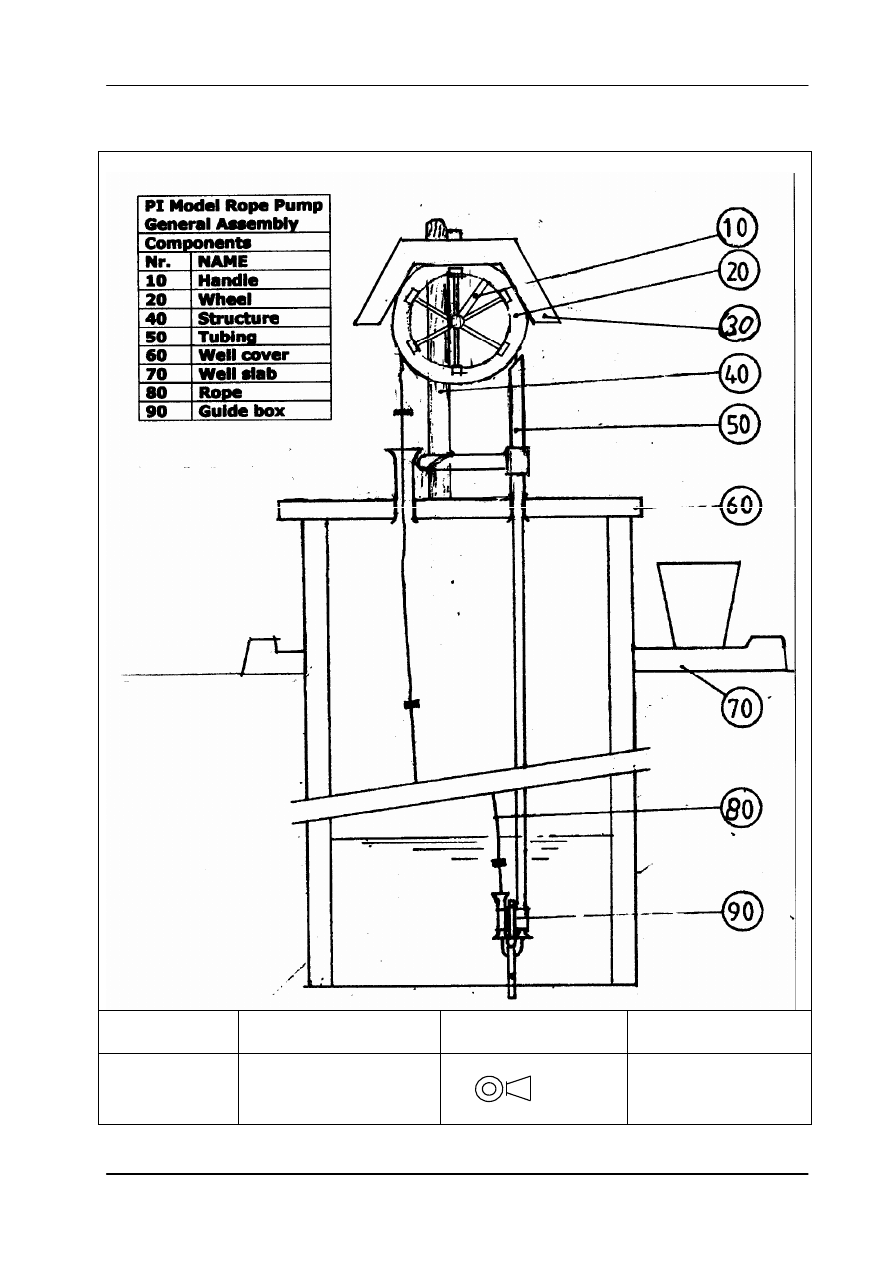
Numbering
The pump drawing gives a total view of the rope pump and the main components are
coded with numbers 10 to 90.
The parts of each component have additional numbers; e.g.
Pump handle is: 10 -1
Drawing system:
The 2 –D American Projection drawing system is used following general engineering
standards,
Modifications:
The pump model version of this manual is defined by the date on the manual.
All drawings in this manual have the same date. All data given in this manual on parts,
description of production steps, etc. refer to the pump model version of this date.
All eventual forthcoming, updated versions, will be documented in drawings with a new
date.
Training Manual PI-Model Rope Pump, Module 1, Production
Arrakis
7
1.2 Pump drawing
PI - Model
ROPE PUMP
Drawn/Date
JdJ/15-12--005
Scale: Not to scale
GENERAL
ASSEMBLY
Modification/Date
20-09-2006
American projection
ARRAKIS
Training Manual PI-model Rope Pump, Module 1 Production
8
Arrakis
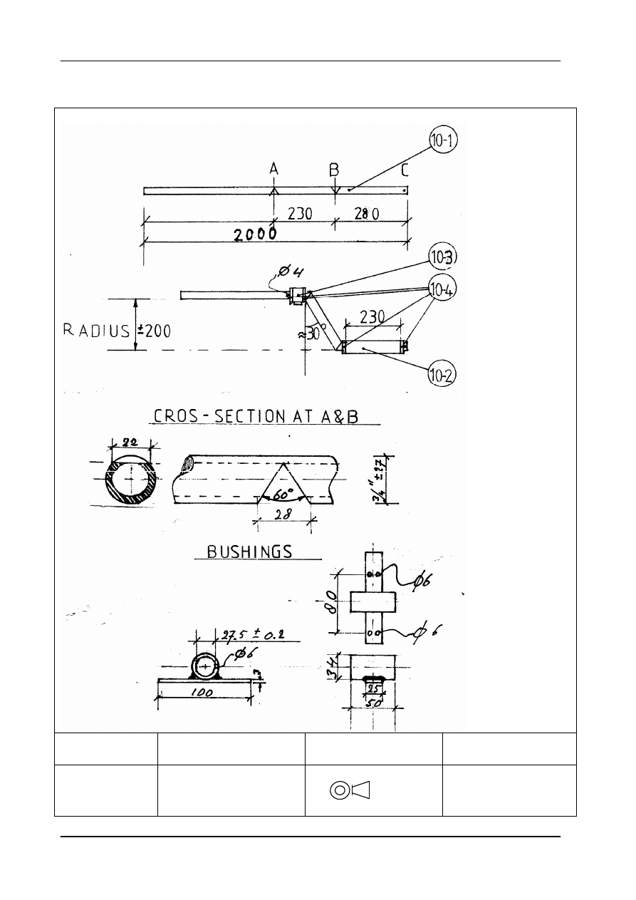
1.3 The Handle (10)
PI - Model
ROPE PUMP
Drawn/Date
JdJ/15-12--005
Scale: Not to scale
PART: HANDLE 10
Modification/Date
20-09-2006
American projection
ARRAKIS
Training Manual PI-Model Rope Pump, Module 1, Production
Arrakis
9
Parts list Handle
Nr
Item
Material
Size Length (mm) Number Remarks
10-1 Handle
Galv. pipe 3/4” 2000
1
Thickwalled pipe
3mm
10-2 Grip
PVC tube 1”
230
1
10-3 Bushing
Galv pipe 1”
50
2
“Thickwalled” pipe
3 mm
10-4 Spacer ring Galv pipe 1”
8
4
,,
10-5 Bushing strip Strip GI
25x3 100
2
Manufacturing Steps
Handle
1 Cut V grooves at spots A and B.
3 Bend and weld; make sure that the tubes stay parallel
4 Weld spacer rings at point A and B with 3 spot welds, on one side
Bushings
5 Drill lubricating holes of 6 mm on top site of bushings 10-3
6 Make sure that clearance Tube/ Bushing does not exceed 0.5 mm
If this is more, reduce size of bushing by cutting a piece , and tack weld again
7 File sharp edges, makes sure inside weld of tubes is smooth
8 Drill holes of 6 mm in bushing strips, 2 holes on top site, and 2 holes on bottom site.
File off any burr.
9 Weld bushing strips to bushings, with filler of a piece of 6 mm bar or 3 mm welding
rod. For standardized production use the jig.
10 Mount PVC grip tube and secure end of handle
11 After mounting the first bushing, add spacer ring and tack weld at three points.
Training Manual PI-model Rope Pump, Module 1 Production
10
Arrakis
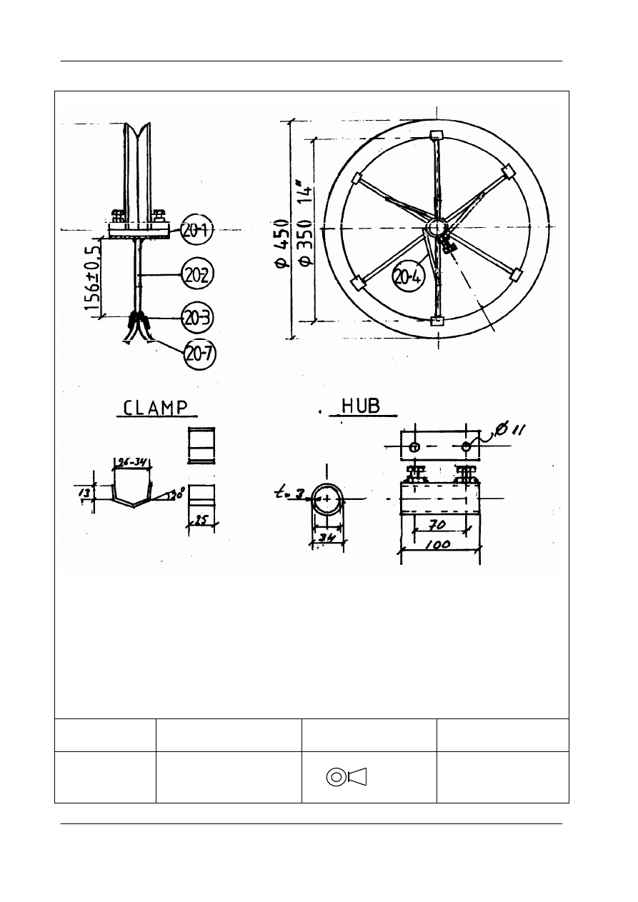
1.4 The wheel (20)
PI - Model
ROPE PUMP
Drawn/Date
JdJ/15-12--005
Scale: Not to scale
PART: WHEEL 20
Modification/Date
20-09-2006
American projection
ARRAKIS
Training Manual PI-Model Rope Pump, Module 1, Production
Arrakis
11
Parts list wheel
Nr
Part
Material
Size Length
(mm)
Amount Observations
20-1
hub
Galv. pipe 1”
100
1
Thickwalled 3 mm
20-2
Spar
Bar,
Ø 10 156 +/-
0.5 mm
6
Depends on size of clamp
, Tight fit between hub and
clamp
20-3
Clamp
Strip
25x3 65
6
Depends on type of tire
20-4
Spar support
Bar
Ø 10 100
3
Optional
20-5 Nut
Galv.
M 10
2
20-6
Bolt
Galv.
M10 25
2
20-7
Wheel rings
Car tire
14”
45
2
Manufacturing steps:
1 Cut all parts, tolerance +/- 1 mm, except indicated otherwise.
2 Cut rings 20-7 of car tire, use a compass.
3 Make clamps 20-3 according to shape of car tire, or cut 11/4” pipe through half
over a length of 25 mm and make two clamps out of it.
4 Drill holes in hub 20-1 and weld nuts 20-5. Weld in steps to avoid damaging of
thread of the bold and nut. Protect thread with grease.
5 Place the clamps over the wheel halves and place the hub with spars inside,
then weld the spars to the clamps.
6 Weld the spar supports to the spars and hub.
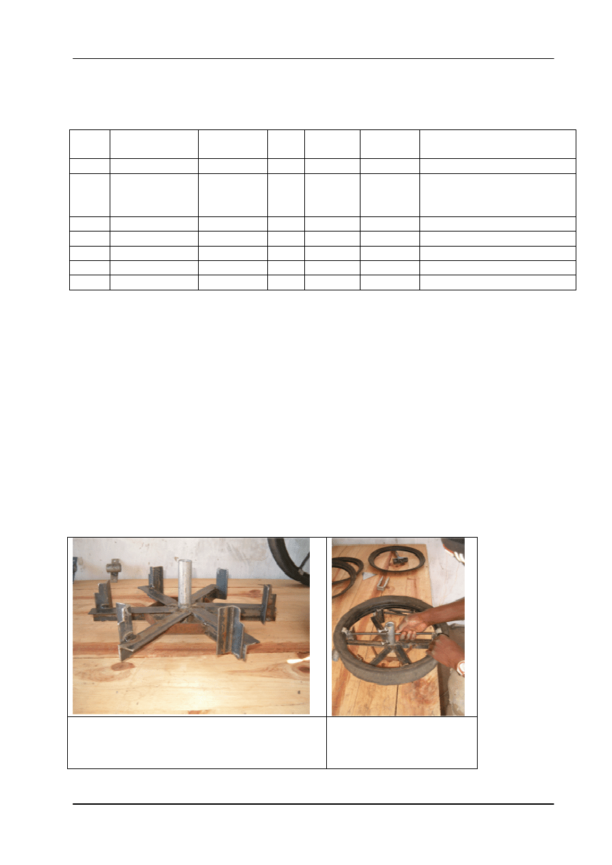
To reduce labour time and to obtain better quality it is advised to use a jig.
Jig for proper assembling of the wheel.
Using a Jig to weld the
clamps and spars to the
Hub. The spars should fit
tightly.
Training Manual PI-model Rope Pump, Module 1 Production
12
Arrakis
1.5
The Cover for Hand dug wells (30)
PI - Model
ROPE
PUMP
Drawn/Date
JdJ/12-July 2006
Scale: Not to
scale
PART:COVER (30)
Modification/Date
20 September 2006
American
projection
ARRAKIS
Training Manual PI-Model Rope Pump, Module 1, Production
Arrakis
13
Parts list
Nr
Item
Material
Size
Length (mm) Number Remarks
30-1 Cover p Galv. sheet 1 mm
1000x200
1
* if 1 mm is not
available, than
minimally 0.6 mm
is allowed.
30-2 Rivets
steel
Ø 3 mm 25 mm
8
Manufacturing steps
1
Cut the plate, file sharp edges
2
Drill 4 crack arrestor holes of 6 mm, at end of cutting lines.
3
Drill 4 holes of 3 mm (the rivet size), as indicated on top view
4
Fold the cover in shape at the dotted lines
5
Make the wooden cover support between the 2 poles
6
Mount cover on the support with 2 galvanised nails
7
Connect cover sides with rivets
8
Drill additional holes for another 4 rivets
9
Mount the rivets
Training Manual PI-model Rope Pump, Module 1 Production
14
Arrakis
1.6
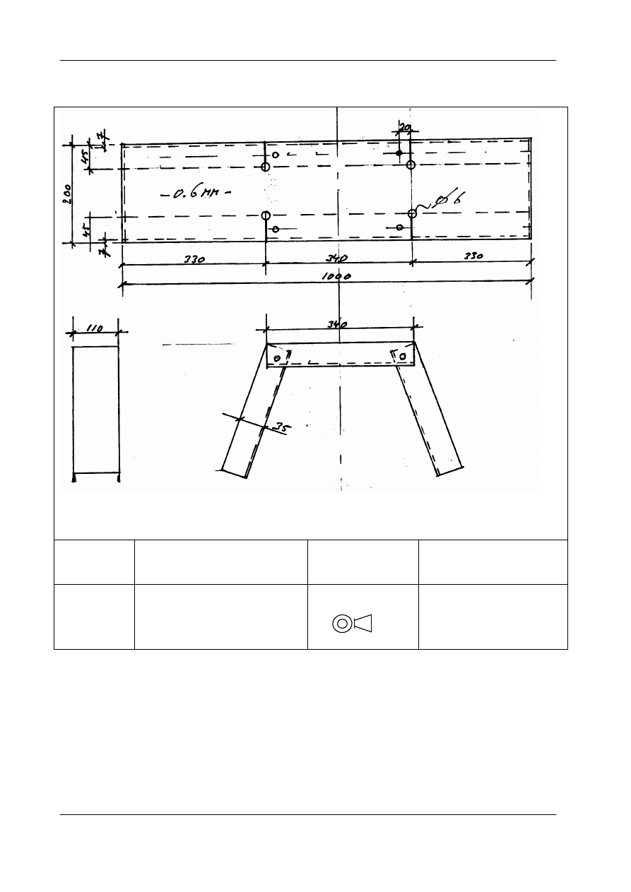
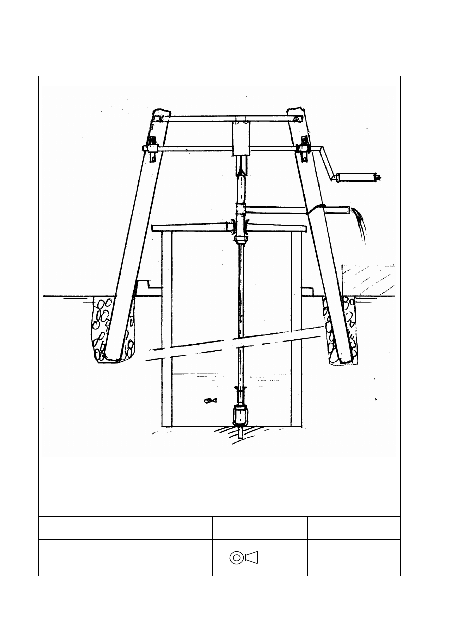
The pump structure for Hand dug wells (40)
PI - Model
ROPE PUMP
Drawn/Date
JdJ/15-12—005
Scale: Not to scale
PART:PUMP
STRUCTURE 40
Modification/Date
12-July 2006
American projection
ARRAKIS

Training Manual PI-Model Rope Pump, Module 1, Production
Arrakis
15
Parts list pump structure
The pump structure consists of two wooden poles of ca 3 a 4 m long and 10 cm thick on
top site. The poles are placed inclined towards each other, to reduce the distance for
the handle.
These poles are placed in dug out holes between 0.5 to 1 m deep, depending on soil
type.
The holes are filled up with stones and sand.
Remark: depending on the height of the well rim and placing of the handle, a platform
may be required to reach belly height of the handle.
The pump structure for Borehole Wells
The pump structure consists of two wooden poles of ca 2.5 to 3 m long and 10 cm thick
on top site. The poles are placed vertically at a distance of 0.5 m., to make the handle
as short as possible. The total pipe length to make the handle is now reduced to 1 m
(instead of 2 m.)
These poles are placed in dug out holes between 0.5 to 1 m deep, depending on soil
type.
The holes are filled up with stones and sand.
Training Manual PI-model Rope Pump, Module 1 Production
16
Arrakis
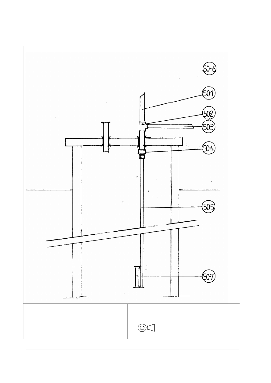
1.7 The tubing (50)
PI - Model
ROPE PUMP
Drawn/Date
JdJ/15-12--005
Scale: Not to scale
PART: TUBING 50
Modification/Date
20-09-2006
American projection
ARRAKIS
Training Manual PI-Model Rope Pump, Module 1, Production
Arrakis
17
1.8 Selection of pump tubing
Diameter of the
tubes depends on total elevation
Elevation means distance between water level and outlet.
The elevation should be measured or estimated for the worst situation which is at the
end of the dry season after some time of continuous pumping.
Recommended diameter of the Pump tube (or pump) tubes:
Elevation 0 - 5 meter Tubes (inside diameter) 40 mm (1½ Inch)
” 5 - 10 meter ” 30 mm (1 Inch)
“ 10 - 20 meter ‘’ 23 mm ( ¾ Inch)
“ 20 - 35 meter ‘’ 18 mm ( ½ Inch)
“ 35 - 60 meter ‘’ 18 mm ( ½ Inch) Double handle
At the top, the top tube and outlet tube diameter should be one size bigger or double the
diameter of the pump tube tube. The outlet tube should be fixed to the pump structure
or another fixed point.
Parts list tubing
For 10 m elevation
Nr
Item
Material Size
Length (m) Number
50-1 Top-tube
PVC tube 1 ½ ”
Ca. 0.5 m
1
50-2 T-joint
PVC tube 1 ½ ”
-
1
50-3 Outlet tube
PVC tube 1 ½”
1 .5 m
1
50-4 Reducer
PVC
1 ½ - 1” -
1
50-5 Pump tube (or rising main) PVC tube 1 ”
6 m
2
50-6 Return tube
PVC tube 1 ½ ”
Ca 0.3 m
1
50-7 Return inlet
PVC tube 1 ½”
0.3 m
1
Manufacturing steps.
Normally the pump is mounted during the installation
Preparations are
1 Make flares at lower end of pump tube 50-5 and upper end of return inlet tube 50-7.
3 Make sure all PVC tubes have good connections (see installation part)
4 Make sure guide box tubes are mounted
5 Select top-tube, T-piece and reducer
Training Manual PI-model Rope Pump, Module 1 Production
18
Arrakis
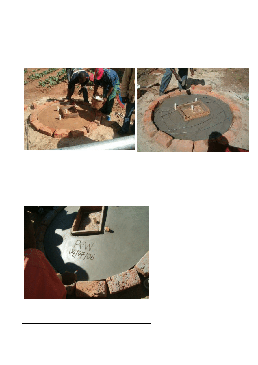
1.9 Construction of well cover for hand dug well (60)
The well cover can be made, either in 2 halves, or in one conically shaped cover with a
small square lid for installation and maintenance purposes.
The mould is made, and tubes should be
properly positioned.
Some reinforcement bars 6 mm plus wire
shopuld be placed. Not yet completed at the
picture.
Prepare cement and put it in the form of the well cover
Standard diameter of cover is 1.20 m, but depending on well dimensions it could be
taken different.
Important: The finished well cover should be left
unused for about minimally one week for the cement
to cure. The cover should be kept wet, continuously!
Training Manual PI-Model Rope Pump, Module 1, Production
Arrakis
19
1.10
Rope with pistons (80)
Rope
Polypropylene (PP) rope gives the best results.
Nylon can also be used, it is stronger than PP rope but it tends to “slide”. To avoid
slipping it can be roughened with a stone or hacksaw. Also the wheel V grove can be
roughened with a hack saw.
Rope length : twice the depth of the well, + 3 meters , + 5% (for the knots)
Rope thickness: For wells up to 35 m. the rope should preferably be 6 mm, but 5 mm is
allowed as well. For wells deeper than 35 meter, it is recommended to use rope of 6
mm.
Pistons
Pistons can be made of different materials but most common are Rubber or PE.
Rubber pistons can be made out of the side part of the car tire used to make the wheel.
The rubber should not be too thick, maximum 4 mm, to be able to cut it with a knife or
scissors.
Diameter of new pistons should be maximally 0.5 mm less than the inside diameter of
the pump tube.
It is important that the hole is in the middle!
A special marker tool can be made to mark the piston, and keeping the hole in the
middle.
Piston made of rubber and a tool (a punch) to make standardized pistons
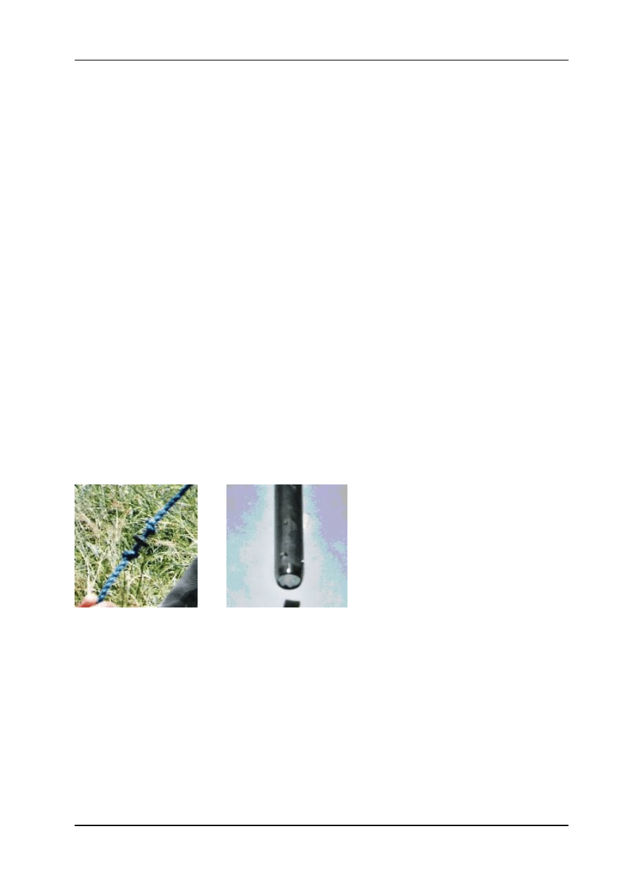
Mounting of Pistons
• Number of pistons: sufficient for the complete rope placed at every one (1) meter.
• Pistons can be fixed to the rope with two knots.
Training Manual PI-model Rope Pump, Module 1 Production
20
Arrakis
1.11
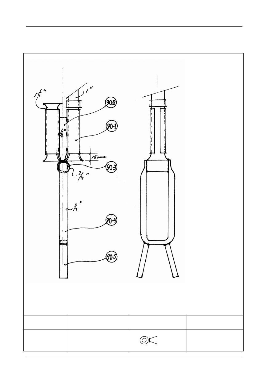
Guide box for Hand Dug Well (90)
PI - Model
ROPE PUMP
Drawn/Date
JdJ/15-12--005
Scale: Not to scale
PART:
GUIDE BOX 90
Modification/Date
20-09- 2006
American projection
ARRAKIS
Training Manual PI-Model Rope Pump, Module 1, Production
Arrakis
21
Parts list guide box based on a 1“ pump tube tube.
The indicated parts change with changing pump tube diameter
Nr
Item
Material Size Length
(mm)
Number Observations
90-1-A Tube clamp for
pump tube
Galv.
pipe
1 “ 80
1
Depending on
size of pump
tube*
90-1-B Tube clamp for
return tube
Galv pipe 1 ¼” 80
1
Depending on
size of pump
tube*
90-2
Connect pipe
Galv
Pipe
½ ” 80
1
Flattened at the
end
90-3
Rope guide
Galv pipe 3/4 ” 45
1
90-4
Rope container
Galv pipe ½ ” 400
1
90-5
Bottom connector
Galv pipe ½ “ 100
2
• Size of clamps are according to size of pump tube
• In case of 1” tubes, tube clamp for return tubes should be 1 1/4 “ as in table.
• In case of ¾” tubes, tube clamps for return tubes should be 1 “
• In case of ½” tubes, tube clamps for return tubes should be ¾”
Manufacturing steps
1 Tube clamps to be cut open and bend outwards, until PVC pipes fit. After mounting of
pump tube and return tube in the clamps, the clamps can be tightened, with care, in a
vice. Take care not to deform the PVC tubes in an oval shape so that the pistons cannot
pass any more.
2 File sharp parts
2 Bend rope container and flatten pipe ends
3 Weld pipe 90-2 to rope guide
4 Weld rope container to rope guide
6 Weld tube clamps to pipe 90-2
For Boreholes with well casings of 3” or 2”, the Guide boxes are slightly
different, because they have to fit in the casings.

Training Manual PI-model Rope Pump, Module 1 Production
22
Arrakis
1.12
Painting
To avoid corrosion, it is essential to paint the parts that have not been galvanized or
where galvanization is damaged.
Steps :
• Remove all grease and oil with solvent,
• Remove all welding slack and rust with a hammer and steel brush.
Make sure that your hands are free of grease.
• Paint first with anticorrosive primer paint. Paint the strip used for the wheel clamps.
Allow painted objects to dry in the shade and NOT in the sun.
When dried in the sun blisters will occur.
• After it is completely dry, paint all metal parts with finish paint (on oil basis).
Make sure hands are free of grease during handling of objects.
Do not dilute the paint, except when it is really necessary (when the paint is too thick
and can only be applied with great resistance). Use only paint diluter and nothing else.
Close the paint cans carefully after painting. Hold the can up side down for some time to
control the closure and to let the paint inside lock the seam of the lid.
Training Manual PI-Model Rope Pump, Module 1, Production
Arrakis
23
ANNEXES
ANNEX I Material list. One complete pump
The material list consists of 2 pages.
Table 1 contains all the parts with fixed dimensions, regardless of the pumping depth.
Four tables number 2 a till 2 d contain the parts with variable dimensions, because
PVC tubing for pump size and casing depends on total elevation height (from lowest
waterlevel to highest outlet point).
For each of the following elevation heights, a separate table 2 is given.
Elevation
[m]
Rising main
diameter
Table
0-5
1½”
2a
5-10
1”
2b
10-20
¾”
2c
20-35
½”
2d
Training Manual PI-model Rope Pump, Module 1 Production
24
Arrakis
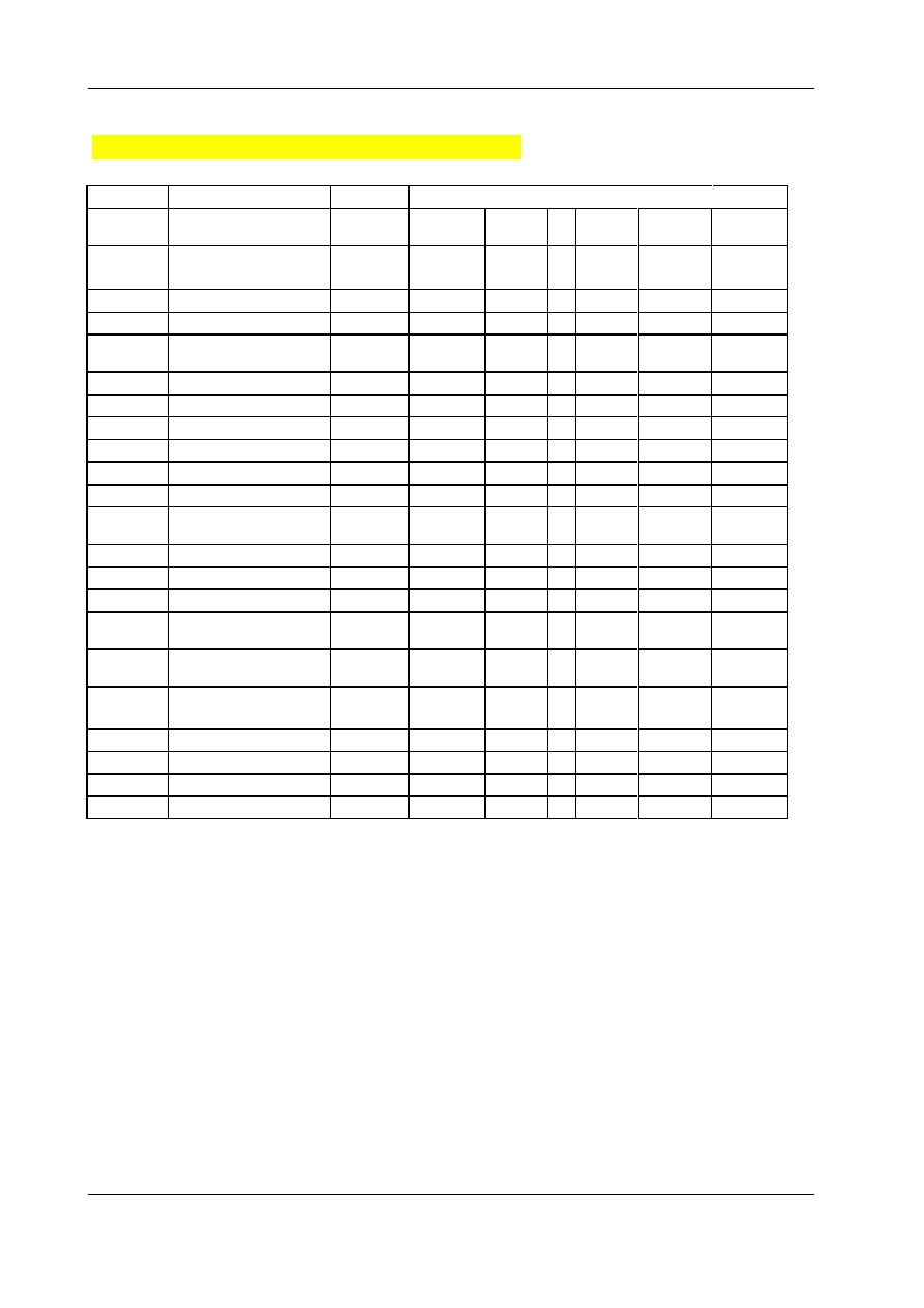
Table 1
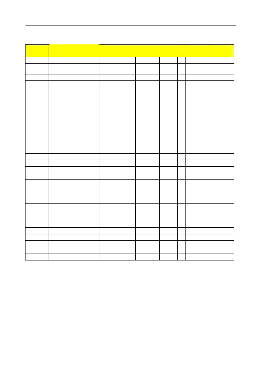
For PI Hand Rope Pumps
TOTAL MATERIAL
LIST
Parts with fixed dimensions
Nr. Sub
Part
Material
Size
Part
Nr Total
Remarks
assembly
Length
Net
Length
Nr.
(m)
(m)
Galv pipe
1 1/4"
0.08
1
0.08
Galv. pipe
1"
0.3
1
0.3
wall
thickness
3.25 mm
Galv. pipe
¾ ”
2
1
2
wall
thickness
2.5 mm
Galv. pipe
½ ”
1.5
1
1.5
Wall
thickness
2.5 mm
30_1
Cover Plate
Galv Sheet
0.6 - 1
mm
1
1
1
width 200
mm
40-1
legs
Wooden poles
3
2
6
Bar
Ø 10
1.5
2
3
Strip
25x3
1.5
1
1.5
20_6
Galv. Nuts and bolts
Bolt
M10x25
6
6 or 3/8 ""
wire
Galv wire
1.5 mm
10
1
10
20_7
Wheel rings
Car tire, used
14”
2
2
Eventually
15" , not
damaged
10.2
Handle grip
PVC Tube
1”
0.5 1
0.5
Wall
thickness
approx.
1.8 mm
Nails
GI nails
70 mm
10
PVC Glue
Small tin or tube
1
1
Car Oil (10 W 40)
Litre
1
1
1
Paint anti corrosive
Litre
1
1
1
Paint Gloss
Liter
1
1
1
Training Manual PI-Model Rope Pump, Module 1, Production
Arrakis
25
Table 2a
PARTS for ELEVATION HEIGHT 0- 5 meter
TOTAL MATERIAL LIST
Nr. Sub
Part
Material Size
Part
Nr Added
Total
Net
Remarks
assembly
Length
Parts
Length Nr.
mm
Length per Mat
Size
Pump
PVC
Tube
50-5
Pump tube
PVC
tube
1 ½ "
6
1
6
1
50-1
Top-tube
PVC
tube
2"
0.5
1
0.5
50-7
Return inlet
PVC
tube
2"
0.3
1
0.3
50-6
Return tube
PVC
tube
2"
0.7
1
0.7
50-2
T-joint
PVC
tube
2"
-
1
50-3
Outlet tube
PVC
tube
2"
1.5
1
1.5
50-4
Reducer
PVC
2 - 1 ½ "
-
1
80 Rope
Poly pr.
6 mm
14
1
14
2
60 Cover
Concrete
Cement Bag
50kg
2
3
70 Slab
Concrete
Cement Bag 50
kg
2
3
60 & 70
Reinforcement
bars
Iron rod 6 mm
8
1
8
Remarks
1
pump height 0- 5
m
*
2
Optional Nylon
rope
3 Depending on size
Elevation height is distance between water level (at its lowest point) to outlet.
Training Manual PI-model Rope Pump, Module 1 Production
26
Arrakis
Table 2b
PARTS for ELEVATION HEIGHT 5 - 10 meter
TOTAL MATERIAL
LIST
Nr. Sub
Part
Material
Size
Part
Nr Added
Total
Net
Remarks
Len
assembly
Length
Parts
gth
Nr.
(m)
Length per Mat
(m)
Size
Pump
PVC
Tube
50-5
Pump tube
PVC tube 1"
6
2
12
1
50-1
Top-tube
PVC tube 1 ½ "
0.5
1
0.5
50-7
Return inlet
PVC tube 1 ½ "
0.5
1
0.5
50-6
Return tube
PVC tube 1 ½ "
0.7
1
0.7
50-2
T-joint
PVC tube 1 ½ "
-
1
50-3
Outlet tube
PVC tube 1 ½”
1.5
1
1.5
50-4
Reducer
PVC
1 ½” - 1"
-
1
80 Rope
Poly pr.
6 mm
26
1
26
2
60 Cover
Concrete
Bag 50
kg
2
3
70 Slab
Concrete
Bag 50
kg
2
3
60 & 70
Reinforcement bars
Iron rod
6 mm
8
1
8
Remarks
1 pump height 5- 10 m
*
2 Optional Nylon rope
3 Depending on size
Training Manual PI-Model Rope Pump, Module 1, Production
Arrakis
27
Table 2c
PARTS for ELEVATION HEIGHT 10 - 20 meter
TOTAL MATERIAL
LIST
Nr. Sub
Part
Material
Size
Part
Nr Added Total Net Remarks
Len
assembly
Length
Parts
gth
Nr.
(m)
Length per Mat
(m)
Size
Pump
PVC Tube
50-5
pump tube
PVC tube 3/4"
6
4
24.0
1
50-1
Top-tube
PVC tube 1 "
0.5
1
0.5
50-7
Return inlet
PVC tube 1 "
0.5
1
0.5
50-6
Return tube
PVC tube 1 "
0.7
1
0.7
50-2
T-joint
PVC tube 1 "
-
1
50-3
Outlet tube
PVC tube 1”
1.5
1
1.5
50-4
Reducer
PVC
1" – ¾ “
1
1
1.0
80
Rope
Poly pr.
6 mm
46
1
46.0
2
60
Cover
Concrete
Bag 50 kg
2
3
70
Slab
Concrete
Bag 50 kg
2
3
60 & 70
Reinforcement bars
Iron rod
6 mm
8
1
8.0
Remarks
1 pump height 10- 20 m
*
2 Optional Nylon rope
3 Depending on size
Training Manual PI-model Rope Pump, Module 1 Production
28
Arrakis
Table 2d
PARTS for ELEVATION HEIGHT 20 - 35 meter
TOTAL MATERIAL
LIST
Nr. Sub
Part
Material
Size
Part
Nr Added
Total
Net
Remarks
Len
assembly
Length
Parts
gth
Nr.
Length per Mat
(m)
(m)
Size
Pump
PVC
Tube
50-5
Pump tube
PVC tube ½ "
6
7
42.0
2
50-1
Top-tube
PVC tube 1 "
0.5
1
0.5
50-7
Return inlet
PVC tube 1 "
0.5
1
0.5
50-6
Return tube
PVC tube 1 "
0.7
1
0.7
50-2
T-joint
PVC tube 1 "
-
1
50-3
Outlet tube
PVC
tube
1”
1.50 1
3.0
50-4
Reducer
PVC
1" – ½ “
-
1
40-6
Tube support holder
Galv pipe 1"
0.03
1
0.03
3
80
Rope
Poly pr.
6 mm
82
1
82.0
4
60
Cover
Concrete
Bag 50
kg
2
3
70
Slab
Concrete
Bag 50
kg
2
3
60 & 70
Reinforcement bars
Iron rod
6 mm
8
1
8.0
Remarks
1 pump height 20- 35 m *
2 Optional Nylon rope
3 Depending on size
Wyszukiwarka
Podobne podstrony:
june 2007 uppersecondary teachers
june 2007 uppersecondary students
GDLS June 2007
31 may 1 june 2007 interim meeting
ZPL Productleaflet Ambra AmbraT 2007
Volkswagen Golf Variant 2007, Golf Variant 2010, Jetta 2005 Auxiliary heater Edition 03 2010 Work
Interchar 212 Application Manual 7 june 06
Watsu I The Transition Flow Photo Manual 2007 8
ACURA 2004 2007 TL Backup Sensors Owner s Manual
2007 Weapons Manual
manual pc diagmonitor 02 2007 en
Ex Motor Manual PL 2007 01 01
PDOP 2007
Prezentacja KST 2007 new
Podstawy MN 2007
Prezentacja JMichalska PSP w obliczu zagrozen cywilizacyjn 10 2007
więcej podobnych podstron